MAXA-MISER VR028A15M/H User manual

PAGE 1
I - Shipping And Packing List
Package 1 of 2 contains:
1 - Energy Recovery Ventilator Assembly
1 - Outdoor Fresh Air Hood w/ Filter
1 - Outdoor Exhaust Hood w/ Barometric Dampers
Package 2 of 2 contains:
1 - Balancing Damper Assembly
1 - Platform Support Rail
2 - Door Panels
1 - Bag Assembly
1 - Roll of ¾" x 1 ¼" gasket
1 - 272" of 18" x ½" gasket
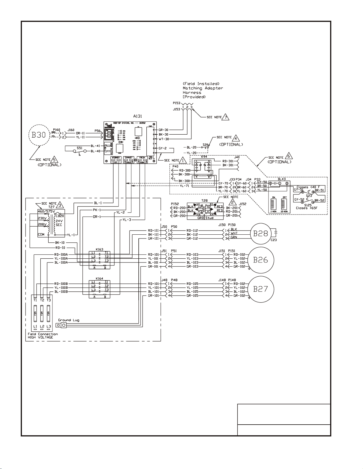
1 - Field Wiring Harness
1 - Adapter Wiring Harness
10 - #14 Screws
30 - #10 x ½" Gold Screws
1 - Installation Instructions
II - Shipping Damage
Check unit for shipping damage. Receiving party should
contact last carrier immediately if shipping damage is
found.
III - General
Theseinstructionsareintendedasageneralguideanddo
not supersede local codes in any way. Authorities having
jurisdiction should be consulted before installation.
IV - Requirements
When installed, the unit must be electrically wired and
grounded in accordance with local codes or, in absence of
local codes, with the current National Electric Code,
ANSI/NFPA No. 70.
V - Application
Unitary Energy Recovery Ventilator (UERV)are used with
3 to 6 ton rooftop units equipped with a balancing
damper assembly. These wheels conserve energy by
mixing warmer air with cooler air in the following manner:
Recovery Wheel Mode
The Recovery Wheel mode is accomplished by two
blowers providing continuous exhaust of stale indoor air
and replacement by equal amount of outdoor air. Energy
recovery is achieved by slowly rotating the energy
recovery wheel within the cassette frame work. In winter,
the UERV adsorbs heat and moisture from the exhaust air
stream during one half of a complete rotation and gives
them back to the cold,drier intake air supply during the
otherhalfrotation.Insummer,theprocessisautomatically
reversed. Heat and moisture are absorbed from incoming
fresh air supply and transferred to the exhaust air stream.
This process allows outdoor air ventilation rates to be
increased by factors of three or more without additional
energy penalty or increase in size of heating or air
conditioning systems.
VI - Rigging Unit For Lifting
1. Maximum weight of unit is —- 750 Lbs. (Crated)
2. Remove crating. Then remove access panel to
retrieve bag assembly. Replace access panel.
3. All panels must be in place for rigging.
4. Liftinglugsaresuppliedwiththe unit.Loosenmachine
bolts and rotate lifting lug.
CAUTION
Danger of sharp metallic edges. Can cause injury.
Take care when servicing unit to avoid accidental
contact with sharp edges.
WARNING
Electric shock hazard. Can cause injury
or death. Before attempting to perform
any service or maintenance, turn the
electrical power to unit OFF at
disconnect switch(es). Unit may have
multiple power supplies.
MAXA-MI$ERÔ
UNITARY ENERGY RECOVERY VENTILATOR
MODEL VR028A15M/H & VR028A25H (STATIONARY)
INSTALLATION
INSTRUCTIONS 035-19268-002-A-0709 / R28A-18YDW
VII - Installation
1. Disconnect all power to rooftop unit.
2. Remove the rooftop unit horizontal and return air
access panels. Also remove any hoods and/or power
exhaust equipment. Discard hoods, power exhaust
equipment horizontal supply and return air access
panels. See Figure 1.
3. Remove return duct cover in the floor of rooftop unit.
ETL Certified per UL 1995
and CSA 22.2
Energy recovery COMPONENT
certifiedto the AHRIAir-to-Air Energy
Recovery Ventilation Equipment
Certification Program in accordance
with AHRI Standard 1060-2000.
Actual performance in packaged
equipment may vary.

4. Remove 9 screws holding painted outside center post
between horizontal return air openings.
5. Remove clip, two screws on the top and two 38" head
screws on the bottom to remove inside galvanized
center post. See Figure 2 and 3.
6. Install balancing damper assembly. Reinstall painted
outside center post. See Figure 4 and 5.
7. Adjust balancing damper to minimum air flow
requirements by loosening the set screw and moving
adjustable rod to desired setting. See Figure 6.
8. Locate the provided field wiring harness and plug into
the economizer plug of the rooftop unit. If rooftop unit
has 12 pin plug, the provided adapter will be needed.
Route field harness through balancing damper so
connection can be made to UERV after installation.
See Figure 7.
9. Locate the two provided door panels. Secure the door
panels to the horizontal return openings using the
provide #10 x ½" screws. See Figure 8.
10. Locate the provided platform support rail. Align the
platform support rail with the center post of the rooftop
unitsreturnopening.Attachtheplatformsupportrail to
the upper set of holes in the door panel using the
provided #14 screws. See Figure 9.
11. Usingliftinglugs,raiseUERVunitapproximatelythree
(3) feet. Remove nut and bolt assembly to slide
telescoping part of leg out of guide. Position standoff
legs so that flat foot is on bottom of stand and reinstall
nut and bolt assembly. Do not fasten tightly,
adjustment will need to be made when unit is put into
position.
12. Apply the provide ¾" x 1 ¼" gasket down the center of
the UERV back panel and between platform support
rail and door panels.
13. Lift and move UERV unit into position in front of
horizontal exhaust air opening.
Note: A treated 2" x 6" x 60" piece of wood or
equivalent should be used under feet of standoff
legs to prevent roof penetration.
14. Remove screws from top panel of rooftop unit. Ensure
top will move up at least 2".
15. Lower UERV into bottom support plate catching the
frontedge oftheUERVbottomintothe½"flange.With
theUERVinplace,adjustthestandofflegstoleveland
support UERV against rooftop unit. Tighten securely.
Rotate lifting lug to original position and tighten
machine bolts
16. PlaceUERVtopflangeundertherooftopunittoppanel
secure the rooftop unit top panel with existing screws.
See Figure 10.
17. Securethesideflangesof theUERVtotheholesinthe
door panels installed earlier with the provide #10 x ½"
screws.
18. Locate the plug extended from back of UERV through
opening in door panel. Connect this plug to the field
wiring harness installed earlier.
PAGE 2
Figure 1
Figure 2
Figure 3
REMOVE
REMOVE
FILTER ACCESS
REMOVE
MAXA-MI$ERÔ
UNITARY ENERGY RECOVERY VENTILATOR
MODEL VR028A15M/H & VR028A25H (STATIONARY)
INSTALLATION
INSTRUCTIONS 035-19268-002-A-0709 / R28A-18YDW

PAGE 3
19. Seal, if required, along face (top and sides) of UERV
unit where it meets rooftop unit to insure no air
leakage. Final assembly should resemble Figure 11.
20. All electrical connections must conform to any local
codes and current National Electric Codes (NEC) and
Canadian Electric Codes (CEC). Refer closely to unit
wiring diagram in unit and/or in these instructions for
properwiringconnections.Refertotheunitnameplate
for minimum circuit ampacity and maximum
overcurrent protection size. Electrical data is listed on
unit rating plate and motor nameplates.
21. Connect line voltage power supply to UERV unit from
disconnect switch. Connect line voltage to fuse block
in control box through knockout on the front of UERV.
See Figure 13.
22. Ground unit with a suitable ground connection either
through unit supply wiring or an earth ground.
Note: Unit voltage entries must be sealed weather
tight after wiring is complete.
23. ReplaceaccesspanelontotheUERVunitandsecure.
24. Restore power to unit.
25. Start system up to verify operation.
26 Balancing is done by removing the plastic plugs in
door panels (4 total).
27. With a manometer measure pressure drop [ inches of
water column] across the top half of UERV (top holes
in door panel). Unit CFM is determined by referring to
Table #1. If CFM values are not per design, adjust
internal dampers inside the rooftop unit. This is
accomplished by removing door panel at the return air
opening,loosing screwincenterofdamper,thenslide
damper rod up or down in the return airstream and
re-tighten screw. Replace door panel and repeat
measurement method.
28. Place plastic plugs back into door panels.
29. Cleanup once UERV is operating properly. Caulk any
open joints, holes or seams to make the unit
completely air and water tight.
30. Fill out installation checklist and start-up sheet in back
of this instruction.
31. Leave this instruction manual with owner or in an
envelope to be kept near the unit.
VIII - Operation
How It Works
The unit contains an Energy Recovery Wheel (ERW) that
is a new concept in rotary air-to-air heat exchanger.
Designed as a packaged unit for ease of installation and
maintenance, only matching up to rooftop unit with an
internal balancing damper and connection of electrical
power is required to make the system operational. The
conceptconsistsof a uniquerotaryenergyrecovery wheel
that rotates in and out of fresh air streams within a heavy
duty, permanently installed blower cabinet that provides
ready access to all internal components. The media is
polymericmaterialthatiscoatedandpermanentlybonded
with a dry desiccant for total enthalpy recovery. The wheel
is belt driven by PSC motor and drive belt.
Figure 5
Figure 6
Figure 4
ADJUSTMENT ROD
REINSTALL CENTER POST
BALANCING DAMPER
MAXA-MI$ERÔ
UNITARY ENERGY RECOVERY VENTILATOR
MODEL VR028A15M/H & VR028A25H (STATIONARY)
INSTALLATION
INSTRUCTIONS 035-19268-002-A-0709 / R28A-18YDW

PAGE 4
When slowly rotating through counter flowing exhaust and
fresh air streams the UERV adsorbs sensible heat and
latent heat from the warmer air stream and transfer this
totalenergytothecooler air stream during the second half
of its rotating cycle. Rotating at 60 revolutions per minute,
thewheelprovidesconstantflowofenergy fromwarmerto
cooler air stream. The large energy transfer surface and
laminar flow through the wheel causes this constant flow
of recovered energy to represent up to 85% of the
difference in total energy contained within the two air
streams.
Sensible and latent heat are the two components of total
heat.Sensibleheatisenergycontainedindryairandlatent
heat is the energy contained within the moisture of the air.
The latent heat load from the outdoor fresh air on an air
conditioning system can often be two to three times thatof
the sensible heat load and in the winter it is a significant
part of a humidification heat load.
During both the summer and winter, the UERV transfers
moisture entirely in the vapor phase. This eliminates wet
surfacesthatretaindustandpromotefungalgrowthaswell
astheneedforacondensatepananddraintocarrywater.
Becauseitisconstantlyrotatingwhenintheairstream,the
UERV is always being cleared by air, first in one direction
then the other. Because it is always dry, dust or other
particles impinging on the surface during one half cycle,
are readily removed during the next half cycle.
Additional Information for Options are provided in
Options Manual.
Recovery Mode
On a thermostat call for blower operation in heating,
coolingorcontinuous blower, theERWwillrotatebetween
fresh air and exhaust air streams. Both the fresh air and
exhaust air blowers will also be operating to overcome the
air resistance of the UERV.
IX - System Check
1. Disconnect main power.
2. Turn thermostat to "Cont" for blower operation.
3. Restore power to unit. Observe UERV wheel rotation
and both fresh air and exhaust air blowers will
operating.
Note: If Low ambient kit is used the jumper between
TB37-5 & TB37-6 should be removed. Also if
system check out is being conducted at low
ambient temperatures, technician should be
aware that this kit can cause system not to
operate.
4. Verify that the UERV (3) three phase blower motors
are phased sequentially ensuring correct rotation and
operation.
a) Disconnect power.
b) Reverse any two field power leads to the UERV.
c) Reapply power.
Figure 7
FIELD HARNESS
Figure 8
Figure 9
DOOR PANELS
PLATFORM SUPPORT RAIL
MAXA-MI$ERÔ
UNITARY ENERGY RECOVERY VENTILATOR
MODEL VR028A15M/H & VR028A25H (STATIONARY)
INSTALLATION
INSTRUCTIONS 035-19268-002-A-0709 / R28A-18YDW

PAGE 5
A - Return Damper Settings
Manuallyadjustpositionofdampers.Thisis accomplished
by loosing and tightening set screw on positioning rod.
B - Blower Speed Adjustment
Blower speed selection is accomplished by changing the
sheave setting on both fresh air and exhaust air blowers.
Both blowers are factory set at "closed" for maximum
airflow. To determine air flow setting, external static
pressure readings will need to be read across the UERV.
See Figure 11 and 12 for location to take pressure
readings.
C - Air Balancing Adjustment
1. Remove plastic plugs in door panels(4 total).
2. With a manometer measure pressure drop [inches of
water column] across top half of UERV (top holes in
door panel). Unit CFM is determined then by referring
to Table #1. If CFM values are not per design, adjust
intake motor sheave and repeat measure method.
3. RepeatthesameprocessforthebottomhalfofUERV.
If CFM values are not per design, adjust internal
dampers inside the rooftop unit. This is accomplished
by removing door panel at the return air opening,
loosing screw in center of damper, then slide damper
rod up or down in the return airstream and re-tighten
screw. Replace door panel and repeat measurement
method.
4. Place plastic plugs back in to door panels.
X - Maintenance
Motor Maintenance
All motors use prelubricated sealed bearings; no further
lubrication is necessary.
Mechanical Inspection
Make visual inspection of dampers, linkage assemblies
and UERV rotating bearings during routine maintenance.
Filters should be checked periodically and cleaned when
necessary. Filter is located in fresh air hoods. DO NOT
replace permanent filters with throwaway type filters.
Belt Alignment
Proper alignment is essential to maintain long V-Belt life.
Belt alignment should be checked every time belt
maintenance is performed, each time the belt is replaced,
and whenever sheaves are removed or installed.
Belt Installation
Always move the drive unit forward so the belt can be
easily slipped into the groove without forcing them. Never
force the belt into a sheave with a screw driver or wedge.
You will damage the fabric and break the cords. It is
recommendedthatthepulleycenter distancesbeoffsetby
¾" for proper length. This will allow the motor assembly to
slideforwardtoremovebeltandbackwardforbelttension.
Belt Tension
Measurethespanlength(centerdistancebetweenpulleys
whenbeltissnug).Markcenterofspan,thenapplya force
(6 to 9 Lbs on new belts) perpendicular to the span large
enoughtodeflectthebelt 164"foreveryinchinspanlength.
Figure 10
Figure 12
UERV TOP FLANGE UNDER RTU TOP
DELTA PRESSURE
(FRESH AIR)
DELTA PRESSURE
(EXHAUST AIR)
Figure 11
MAXA-MI$ERÔ
UNITARY ENERGY RECOVERY VENTILATOR
MODEL VR028A15M/H & VR028A25H (STATIONARY)
INSTALLATION
INSTRUCTIONS 035-19268-002-A-0709 / R28A-18YDW

Energy Recovery Wheel Maintenance
Eight pie-shaped ERW segments, are seated on stops
between the segment retainer which pivots on the wheel
rim and secured to the hub and rim of wheel. Annual
inspection of the self cleaning wheel is recommended.
With power disconnected, remove UERV access panels
(rear) and unplug [J150 and P150] (Refer to wiring
diagrams in this instruction manual). Removesegment
and wash with water and/or mild detergent.
To install wheel segments follow steps A through E . See
Figure 14. Reverse procedure for segment removal.
A. Unlocktwosegmentretainers(oneoneachsideofthe
selected segment opening.
B. With the embedded stiffener facing the motor side,
insertthenoseofthesegmentbetweenthehubplates.
C. Holding segment by the two outer corners, press the
segment towards the center of the wheel and inwards
against the spoke flanges. If hand pressure does not
fully seat the segment, insert the flat tip of a screw
driver between the wheel rim and outer corners of the
segment and apply downward force while guiding the
segment into place.
D. Closeandlatcheachsegmentretainerundersegment
retaining catch.
E. Slowly rotate the wheel 180o. Install the second
segment opposite the first for counterbalance. Rotate
the two installed segment 90o to balance the wheel
while the third segment is installed. Rotate the wheel
180oagain to install the fourth segment. Repeat this
sequence with the remaining four segments.
PAGE 6
B
C
A
D
E
D
HUB
SEGMENT
FIGURE 14
SPOKE
SEGMENT RETAINER CATCH
WHEEL RIM SEGMENT RETAINER
Figure 13
FUSE BLOCK
MAXA-MI$ERÔ
UNITARY ENERGY RECOVERY VENTILATOR
MODEL VR028A15M/H & VR028A25H (STATIONARY)
INSTALLATION
INSTRUCTIONS 035-19268-002-A-0709 / R28A-18YDW

PAGE 7
ENERGY RECOVERY VENTILATOR
SCFM vs. PRESSURE DROP
0.53 0.57 0.60 0.64 0.71 0.78 0.85 0.93 1.00
1.30 1.31 1.31 1.30 1.28 1.26 1.20 1.13 1.04
1.09 1.09 1.09 1.08 1.05 0.99 0.90 0.82 0.75
0.89 0.88 0.87 0.85 0.81 0.75 0.66 0.59 0.5
0.69 0.68 0.65 0.62 0.57 0.5 0.42 0.35
0.25
0.00
0.20
0.40
0.60
0.80
1.00
1.20
1.40
1500 1600 1700 1800 2000 2200 2400 2600 2800
SCFM
Equation of line: SCFM=(PD + 0.01)/0.00036
TABLE #1
PRESSUREDROP(in.ofW.C.)
R28 Series 1100RPM 1000RPM 900RPM 800RPM

PAGE 8

R28-18YDW
UERV UNIT SCHEMATIC DIAGRAM
PAGE 9
Notes:
1. Remove jumper to install field optional low ambient switch.
2. Step-down transformer assembly for 460 volt units.
3. Selective voltage terminal for proper unit voltage
4. Optional low ambient switch.
5. Optional motorized intake damper.
6. Optional stop, start and jog control.
7. Matching adapter harness (provided) to connect with rooftop unit. For energy
management systems connect +24v to green and common 24v to black.
COMPONENT CODE
A131 Fixed Relay Board
B26 Motor, Exhaust Air
B27 Motor, Fresh Air
B28 Motor, Desiccant Wheel
B30 Motor, Damper (Optional)
C23 Capacitor, Wheel Motor
DL43 Delay, Cycle Timer (Optional)
F29 Fuse
J33 Jack, Cycle Control (Optional)
J34 Jack, Cycle Control Harness (Optional)
J40 Jack, Cycle (Optional)
J48 Jack, Control Box (Fresh Air)
J50 Jack, Control Box (Wheel)
J51 Jack, Control Box (Exhaust Air)
J56 Jack, Control Box (Damper)
J148 Jack, Fresh Air Motor Harness
J150 Jack, Wheel Motor Harness
J151 Jack, Exhaust Air Motor Harness
J152 Jack, Transformer (High Voltage)
J153 Jack, Field Harness
J160 Jack, Damper Motor Harness
K94 Relay, On/Off (Optional)
K163 Contactor, Exhaust Air Motor
K164 Contactor, Fresh Air Motor
P33 Plug, Cycle Control (Optional)
P34 Plug, Cycle Control Harness (Optional)
P40 Plug, Wheel Cycle (Optional)
P48 Plug, Fresh Air Motor Harness
P50 Plug, Wheel Motor Harness
P51 Plug, Exhaust Air Motor Harness
P56 Plug, Damper Motor Harness
P148 Plug, Fresh Air Motor
P150 Plug, Wheel Motor
P151 Plug, Exhaust Air Motor
P152 Plug, Transformer (High Voltage)
P153 Plug, Field Harness
P160 Plug, Damper Motor
S23 Thermostat - Low Ambient (Optional)
S26 Switch, Low Ambient (Optional)
S51 Switch, Door
S125 Switch, Ambient Override (Optional)
T27 Transformer, Control
T28 Transformer, Step-down (Optional)
WIRE COLOR
BK Black
BL Blue
GR Green
GY Gray
OR Orange
PK Pink
RD Red
WH White
YL Yellow

PAGE 10
Unit#: 01-R28-01XX-23/-33/-43
Desiccant Wheel for Rooftop Unit
208-230/460V/575V (3 PH)
UERV UNIT WIRING DIAGRAM
Notes:
1. Remove jumper to install field optional low ambient switch.
2. Step-down transformer assembly for 460 volt units.
3. Selective voltage terminal for proper unit voltage
4. Optional low ambient switch.
5. Optional motorized intake damper.
6. Optional stop, start and jog control.
7. Matching adapter harness (provided) to connect with rooftop unit. For energy
management systems connect +24v to green and common 24v to black.

PAGE 11
EQUIPMENT LAYOUT

Unitary 5005 Norman
Products York OK
Group Drive 73069
Supercedes: 035-19268-001-A-1108
Subject to change without notice. Printed in U.S.A.
Copyright © by Unitary Products Group 2005. All rights reserved. 035-19268-002-A-0709
R28A-18YDW
START UP INFORMATION SHEET
VOLTAGE - UERV UNIT
Incoming Voltage L1-L2 L1-L3 L2-L3
Running Voltage L1-L2 L 1-L3 L2-L3
Secondary Voltage C (black) to G (green) Volts*
C (black) to W (white) Volts*
* With thermostat calling.
AMPERAGE - UERV MOTORS
Intake Motor: Nominal HP Rated Amps Running Amps
Exhaust Motor: Nominal HP Rated Amps Running Amps
Wheel Motor: Nominal HP Rated Amps Running Amps
AIRFLOW
Intake Design CFM Pressure Drop Calculated CFM
Exhaust Design CFM Pressure Drop Calculated CFM
Amb. db Temp Return Air db Temp* Tempered Air db Temp*
Amb. wb Temp Return Air wb Temp* Tempered Air wbTemp*
* Measure after 15 minutes of run time
INSTALLATION CHECK LIST
UERV Model # Serial #
Owner Owner Phone #
Owner Address
Installing Contractor Start Up Mechanic
qInspect the unit for transit damage and report any damage on the carrier’s freight bill.
qCheck model number to insure it matches the job requirements.
qInstallfieldaccessoriesandunitadapterpanelsasrequired.Followaccessoryandunitinstallationmanuals.
qVerify field wiring, including the wiring to any accessories.
qCheck all multi-tap transformers, to insure they are set to the proper incoming voltage.
qVerify correct belt tension, as well as the belt/pulley alignment. Tighten if needed.
qPrior to energizing the unit, inspect all the electrical connections.
qPower the unit. Bump the motor contactor to check rotation. Three phase motors are synchronized at the
factory.Ifblowermotorfansarerunningbackwards,de-energizepowertotheunit,thenswaptwoofthethree
incoming electrical lines to obtain proper phasing. Re-check.
qPerform all start up procedures outlined in the installation manual shipped with the unit.
qFill in the Start Up Information as outlined on the opposite side of this sheet.
qProvide owner with information packet. Explain the thermostat and unit operation.
This manual suits for next models
1
Table of contents