MAXDATA FUSION 6000 I User manual

User’s Manual
MAXDATA FUSION 6000 I

2 3MAXDATA FUSION 6000 IContents

2 3MAXDATA FUSION 6000 IContents
Contents
1 Setting up the System 7
Workstation Position ...............................................................................................................................7
Connecting the System ...........................................................................................................................8
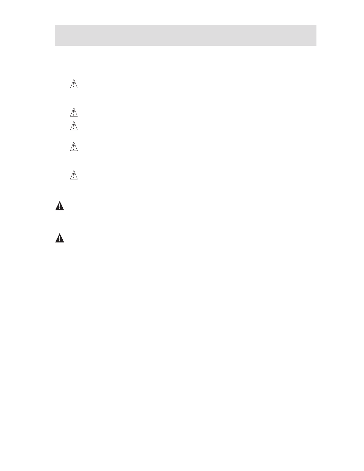
Rear Connectors .................................................................................................................................8
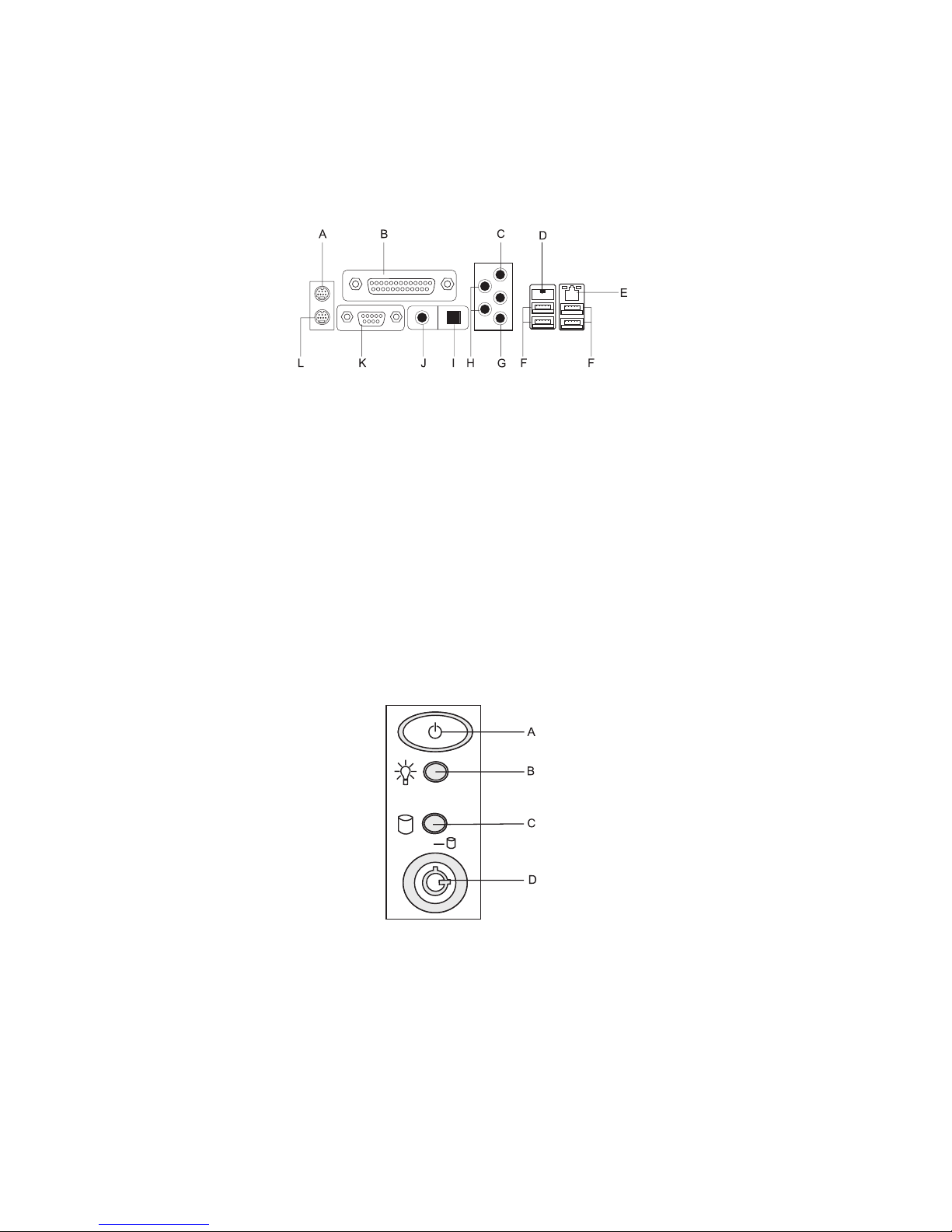
Powering up the System .........................................................................................................................8
2 Board Features 9
Board Components ...............................................................................................................................11
Main Memory ........................................................................................................................................12
Audio Subsystem ..................................................................................................................................13
Input/Output (I/O) Controller ..................................................................................................................14
LAN Subsystem ....................................................................................................................................14
RJ-45 LAN Connector LEDs .............................................................................................................14
Hi-Speed USB 2.0 Support ....................................................................................................................14
Enhanced IDE Interface .........................................................................................................................15
Serial ATA ..............................................................................................................................................15
Expandability .........................................................................................................................................15
BIOS ......................................................................................................................................................15
Serial ATA and IDE Auto Configuration ............................................................................................15
PCI and PCI Express Auto Configuration ..........................................................................................15
Security Passwords ..........................................................................................................................15
Chassis Intrusion ...................................................................................................................................16
Power Management Features ...............................................................................................................16
ACPI .................................................................................................................................................16
Fan Connectors ................................................................................................................................16
Fan Speed Control (Intel® Precision Cooling Technology) ................................................................16
Suspend to RAM (Instantly Available PC Technology) .....................................................................17
Resume on Ring ...............................................................................................................................17
Wake from USB ...............................................................................................................................17
Wake from PS/2 Keyboard/Mouse ...................................................................................................18
PME# Wakeup Support ....................................................................................................................18
Speaker .................................................................................................................................................18
Battery ...................................................................................................................................................18
Real-Time Clock .....................................................................................................................................18
3 Installing and Replacing Board Components 19
Before You Begin ..................................................................................................................................19
Installation Precautions .........................................................................................................................19
Place Battery Marking ......................................................................................................................19
Installing a Processor ............................................................................................................................20
Installing a Processor .......................................................................................................................20
Installing and Removing Memory ..........................................................................................................23
Guidelines for Dual Channel Memory Configuration ........................................................................23
Installing DIMMs ..............................................................................................................................25
Removing DIMMs ............................................................................................................................26
Installing and Removing a PCI Express x16 Card ..................................................................................27
Installing a PCI Express x16 Card .....................................................................................................27
Removing the PCI Express x16 Card ...............................................................................................27
Configuring the System for Intel® Matrix Storage Technology for Serial ATA .......................................28

4 5MAXDATA FUSION 6000 IContents
Configuring the BIOS for Intel® Matrix Storage Technology ............................................................28
Creating your RAID set .....................................................................................................................28
Loading the Intel® Application Accelerator Drivers ...........................................................................28
Setting Up a “RAID Ready” System ................................................................................................28
Connecting Internal Headers .................................................................................................................29
Front Panel Audio Header ................................................................................................................30
IEEE 1394 Headers ..........................................................................................................................30
USB 2.0 Headers ..............................................................................................................................30
Front Panel Header ...........................................................................................................................31
Alternate Power LED Header ...........................................................................................................31
Chassis Intrusion Header .................................................................................................................31
Installing Other Connectors ...................................................................................................................32
Setting the BIOS Configuration Jumper Block ......................................................................................33
Clearing Passwords ...............................................................................................................................33
Setting Up Full 7.1-Channel Surround Sound (Optional) ........................................................................35
Multi-Channel Analog Audio .............................................................................................................35
Multi-Channel Digital Audio ..............................................................................................................35
Replacing the Battery ............................................................................................................................36
BIOS ......................................................................................................................................................39
Using the BIOS Setup Program .......................................................................................................39
Error Messages and Indicators ..............................................................................................................39
BIOS Beep Codes ............................................................................................................................39
BIOS Error Messages .......................................................................................................................39
4 Regulatory and Integration Information 41
Product Regulatory Compliance ............................................................................................................41
Product Safety Compliance ..............................................................................................................41
Product EMC Compliance ....................................................................................................................41
Product Regulatory Compliance Markings ............................................................................................41
Electromagnetic Compatibility Notices .................................................................................................42
Europe (CE Declaration of Conformity) ............................................................................................42
Installation Precautions .........................................................................................................................42
Installation Requirements ......................................................................................................................43
Prevent Power Supply Overload ......................................................................................................43
Place Battery Marking ......................................................................................................................43
Use Only for Intended Applications .......................................................................................................43

4 5MAXDATA FUSION 6000 IContents
Figures
1. Rear connectors ................................................................................................................................8
2. The Controls ......................................................................................................................................8
3. Board Components .........................................................................................................................11
4. Location of Standby Power Indicator ..............................................................................................17
6. Lift the Load Plate and Don’t Touch the Socket Contacts ..............................................................20
5. Lift Socket Lever ............................................................................................................................20
8. Remove the Processor from the Protective Processor Cover and Do Not Touch ..........................21
7. Remove the Protective Socket Cover .............................................................................................21
9. Install Processor ..............................................................................................................................22
10. Close the Load Plate .......................................................................................................................22
11. Dual Configuration Example 1 .........................................................................................................23
12. Dual Configuration Example 2 .........................................................................................................23
13. Dual Configuration Example 3 .........................................................................................................24
14. Position of DIMM sockets ...............................................................................................................25
15. Installing a DIMM ............................................................................................................................25
16. Removing the PCI Express x16 Card ..............................................................................................27
17. Internal Headers ..............................................................................................................................29
18. Location of Other Connectors .........................................................................................................32
19. Location of the BIOS Configuration Jumper Block ..........................................................................33
20. Back Panel Audio Connectors .........................................................................................................35
21. Removing the Battery .....................................................................................................................38
Tables
1. Feature Summary ..............................................................................................................................9
2. Board Components .........................................................................................................................11
3. Memory Configurations ...................................................................................................................12
4. RJ-45 10/100/1000 Gigabit Ethernet LAN Connector LEDs ............................................................14
5. Front Panel Audio Header Signal Names ........................................................................................30
6. IEEE 1394 Header Signal Names ....................................................................................................30
7. USB 2.0 Header Signal Names ........................................................................................................30
8. Front Panel Header Signal Names ...................................................................................................31
9. Jumper Settings for the BIOS Setup Program Modes ....................................................................33
10. Beep Codes .....................................................................................................................................39
11. BIOS Error Messages ......................................................................................................................39
12. Product Certification Markings ........................................................................................................41

6 MFMAXDATA FUSION 6000 I

MF 7MAXDATA FUSION 6000 ISetting up the System
1 Setting up the System
Workstation Position
Please take note of the following criteria for creating a practical and safe workplace when setting up
your computer:
The system can be used anywhere the temperature is suitable for people. However, rooms
with humidity over 70 %, and dusty or dirty areas are not appropriate. In addition, do not
expose the workstation to any temperatures over +35 °C or under +10 °C.
Make sure that the cables connecting the workstation to peripheral devices are not tight.
Make sure that all power and connection cables are positioned so that they are not trip
hazards.
When you save data to your workstation‘s hard disks or to a floppy disk, they are stored as
magnetic information on the media. Make sure that they are not damaged by magnetic or
electromagnetic fields.
Because the electronics in your computer can be damaged by jarring, no mechanical devices
should be placed on the same surface as the workstation. This is especially important for
impact printers whose vibrations could damage the hard disk.
ATTENTION
In order to fully separate the workstation from current, the power cord must be removed from the
wall outlet.
ATTENTION
To ensure stability, the floor stands must be turned outwards.

8 MFMAXDATA FUSION 6000 ISetting up the System
Connecting the System
Rear Connectors
NOTE
The line out connector, located on the back panel, is designed to power either headphones or amplified
speakers only. Poor audio quality may occur if passive (non-amplified) speakers are connected to this
output.
A. PS/2-Mouse G. MIC
B. Parallel port H. Audio out
C. Line in I. Optical line out
D. IEEE 1394 J. Coaxial line out
E. Gigabit NIC K. Serial port
F. USB ports L. PS/2-Keyboard
Powering up the System
At the front of the case, you can find the necessary controls like power button, reset button and the
HDD Leds. Press the power button one time briefly in order to boot the workstation.
A. Power switch
B. Power LED
C. HDD LED
D. Key Lock
Figure 1. Rear connectors
Figure 2. The Controls

MF 9MAXDATA FUSION 6000 IBoard Features
2 Board Features
This chapter briefly describes the main features of the board.
Table 1 summarizes the major features of the board.
Table 1. Feature Summary
Form Factor • ATX (12.00” x 9.60”) Board
Processor Support for an Intel® Pentium® 4 Processor in the LGA775
package with 800 MHz or 533 MHz front side bus
Main Memory • Four 240-pin, 1.8 V SDRAM Dual Inline Memory Module
(DIMM) sockets
• 533/400 MHz single or dual channel DDR2 SDRAM interface
• Designed to support up to 4 GB of system memory
NOTE: System resources (such as PCI and PCI Express)
require physical memory address locations that reduce avail-
able memory addresses above 3 GB. This may result in less
than 4 GB of memory being available to the operating system
and applications.
Chipset Intel® 925X Express Chipset consisting of:
• Intel® 82925X Memory Controller Hub (MCH) with Direct
Media Interface
• Intel® 82801FR I/O Controller Hub (ICH6-R) supporting Intel®
Matrix Storage Technology
Audio • Intel® 925X Express Chipset
• Intel® high-definition audio codec
Expansion Capabilities • Up to four PCI bus add-in card connectors (SMBus routed
to PCI bus connector 2)
• One PCI Express x16 connector
• One PCI Express x1connector (second connector optional)
• Four Serial ATA (SATA) connectors
• Two front panel USB 2.0 headers
• One front panel audio header
• Two IEEE 1394 headers
LAN Subsystem Marvell 88E8050 PCI Express Gigabit Ethernet Controller
(10/100/1000 Mbit/sec) with RJ-45 connector
BIOS • Intel® BIOS
• 8 Mbit symmetrical flash memory
• Support for SMBIOS
• Intel® Rapid BIOS Boot
• Intel® Express BIOS Update
RAID Intel® Matrix Storage Technology for Serial ATA
continued

10 11MAXDATA FUSION 6000 IBoard Features
Table 1. Feature Summary (Continued)
Peripheral Interfaces • Up to eight USB 2.0 ports
• Four ports routed to the back panel
• Four ports routed to two USB headers
• Four Serial ATA channels, via the ICH6-R, one device per
channel
• Up to three IEEE 1394 ports
• One port routed to the back panel
• Two ports routed to two IEEE 1394 headers
• One IDE interface with ATA-66/100 support
• One diskette drive interface
• One parallel port
• One serial port
• PS/2 keyboard and mouse ports
Power Management • Support for Advanced Configuration and Power Interface
(ACPI)
• Suspend to RAM (STR)
• Wake on USB, PCI,PCI Express, PS/2, LAN, and front panel
Hardware Management Hardware monitor with:
• Four fan sensing inputs used to monitor fan activity
• Remote diode temperature sensing
• Intel® Precision Cooling Technology fan speed control
that automatically adjusts processor fan speeds based on
processor temperature and chassis fan speeds based on
system temperature
• Voltage sensing to detect out of range values

10 11MAXDATA FUSION 6000 IBoard Features
Board Components
Figure 3 shows the approximate location of the major components on board.
Table 2. Board Components
Label Description Label Description
A. PCI Express x1 connectors M. Chassis intrusion header
B. Front panel audio header (yellow) N. BIOS configuration jumper
C. PCI Express x16 connector O. Front chassis fan header (fan speed control)
D. Rear chassis fan header
(fan speed control)
P. Serial ATA connectors (four)
E. Alternate power connector (1x4) Q. Alternate power LED header
F. 12 V power connector (2x2) R. Front panel header
G. Processor socket (LGA775) S. USB 2.0 headers
H. Processor fan header(4-pin, fan
speed control)
T. IEEE 1394 headers (blue)
I. Main power connector (2x12) U. Speaker
J. Diskette drive connector V. PCI bus add-in card connectors
K. IDE connector W. Rear fan header (4-pin)
L. Battery
Figure 3. Board Components

12 13MAXDATA FUSION 6000 IBoard Features
Main Memory
The mainboard supports dual or single channel memory configurations defined in Table 3.
NOTE
To be fully compliant with all applicable memory specifications, the board should be populated with
DIMMs that support the Serial Presence Detect (SPD) data structure. If your memory modules do
not support SPD, you will see a notification to this effect on the screen at power up. The BIOS will
attempt to configure the memory controller for normal operation.
Table 3. Memory Configurations
Memory
Speed
Processor FSB frequency
(MHz)
Memory Speed
Outcome
(MHz)
DDR2 533 Intel® Pentium® 4
Processor
800 533
533 533
DDR2 400 Intel® Pentium® 4
Processor
800 400
533 333
• Four 240-pin Double Data Rate 2 (DDR2) SDRAM Dual Inline Memory Module (DIMMs)
connectors with gold-plated contacts.
• Support for:
- Unbuffered, non-registered single or double-sided DIMMs
- Serial Presence Detect (SPD) memory only
- 1.8 V memory
- Memory configuration listed below:
- Up to 2.0 GB utilizing 256 MB technology
- Up to 4.0 GB utilizing 512 MB or 1 GB technology
NOTE
System resources (such as PCI and PCI Express) require physical memory address locations that
reduce available memory addresses above 3 GB. This may result in less than 4 GB of memory being
available to the operating system and applications.

12 13MAXDATA FUSION 6000 IBoard Features
Audio Subsystem
The board includes a flexible 7.1-channel audio subsystem based on an Intel® high-definition audio
codec:
The audio subsystem features:
• Impedance sensing capability for jack re-tasking
• S/N (signal-to-noise) ratio: > 90 dB
• Power management support for ACPI 2.0 (driver dependent)
• Intel® 82801FR I/O Controller Hub (ICH6-R)
• Realtek Semiconductor Corporation audio codec
• Microphone input that supports:
- Microphone array
- Acoustic Echo (AEC)
- Beam Forming (BF)
- Noise Supression (NX) technology
The subsystem includes the following connectors:
• Front panel audio connector, including pins for:
- Line out
- Mic
• Back panel audio connectors that are configurable through the drivers of the audio devices:
- Line in
- Three Line out
- Mic in or Center LFE out
- Two digital line out:
• One coaxial line out
• One optical (Toslink) line out

14 15MAXDATA FUSION 6000 IBoard Features
Input/Output (I/O) Controller
The super I/O controller features the following:
• Low pin count (LPC) interface
• One serial port
• One parallel port with Extended Capabilities Port (ECP) and Enhanced Parallel Port (EPP)
support
• Serial IRQ interface compatible with serialized IRQ support for PCI systems
• PS/2-style mouse and keyboard interfaces
• Interface for one 1.2 MB, 1.44 MB, or 2.88 MB diskette drive
• Intelligent power management, including a programmable wake up event interface
• PCI power management support
LAN Subsystem
The LAN subsystem provides a Fast PCI LAN subsystem. The LAN subsystem provides the following
functions:
• Marvell 10/100/1000 Gigabit Ethernet LAN
• Support for RJ-45 connector with status indicator LEDs
• Programmable transit threshold
• Configurable EEPROM that contains the MAC address
RJ-45 LAN Connector LEDs
Table 4 describes the LED states when the board is powered up and the 10/100/1000 Gigabit Ethernet
LAN subsystem is operating.
Table 4. RJ-45 10/100/1000 Gigabit Ethernet LAN Connector LEDs
LED Color LED State Indicates
Bi-color LED Off 10 Mbit/sec data rate is selected.
Green 100 Mbit/sec data rate is selected.
Yellow 1 Gbit/sec data rate is selected.
Green LED Off LAN link is not established.
On (pulsing) The computer is communicating with
another computer on the LAN.
Hi-Speed USB 2.0 Support
NOTE
Computer systems that have an unshielded cable attached to a USB port might not meet FCC Class
B requirements, even if no device or a low-speed USB device is attached to the cable. Use a shielded
cable that meets the requirements for a full-speed USB device.
The board supports up to eight USB 2.0 ports via ICH6-R; four ports routed to the back panel and
four routed to two internal USB 2.0 headers. USB 2.0 ports are backward compatible with USB 1.1
devices. USB 1.1 devices will function normally at USB 1.1 speeds.
USB 2.0 support requires both an operating system and drivers that fully support USB 2.0 transfer
rates. Disabling Hi-Speed USB in BIOS reverts all USB 2.0 ports to USB 1.1 operation. This may be
required to accommodate operating systems that do not support USB 2.0.

14 15MAXDATA FUSION 6000 IBoard Features
Enhanced IDE Interface
The ICH6-R’s IDE interface handles the exchange of information between the processor and peripheral
devices like hard disks, CD-ROM drives, and Iomega Zip drives inside the computer. The interface
supports:
• Up to two IDE devices (such as hard drives)
• ATAPI-style devices (such as CD-ROM drives)
• Older PIO Mode devices
• Ultra DMA-33 and ATA-66/100 protocols
• Laser Servo (LS-120) drives
Serial ATA
The board supports four Serial ATA channels via the ICH6-R, connecting one device per channel in
either a RAID or non-RAID configuration.
Expandability
The board supports the following:
• One PCI Express x16 add-in card
• Two PCI Express x1 add-in cards
• Four PCI bus add-in cards
BIOS
The BIOS provides the Power-On Self-Test (POST), the BIOS Setup program, the PCI and IDE auto-
configuration utilities, and the video BIOS.
Serial ATA and IDE Auto Configuration
If you install a Serial ATA or IDE device (such as a hard drive) in your board, the auto-configuration
utility in the BIOS automatically detects and configures the device for your computer. You do not
need to run the BIOS Setup program after installing a Serial ATA or IDE device. You can override the
auto-configuration options by specifying manual configuration in the BIOS Setup program.
When booting from a Serial ATA device, Serial ATA connector 0 is the first boot device and Serial
ATA connector 3 is the last boot device.
PCI and PCI Express Auto Configuration
If you install a PCI/PCI Express add-in card in your board, the PCI/PCI Express auto-configuration
utility in the BIOS automatically detects and configures the resources (IRQs, DMA channels, and I/O
space) for that add-in card. You do not need to run the BIOS Setup program after you install a PCI/PCI
Express add-in card.
Security Passwords
The BIOS includes security features that restrict whether the BIOS Setup program can be accessed
and who can boot the computer. A supervisor password and a user password can be set for the BIOS
Setup and for booting the computer, with the following restrictions:
• The supervisor password gives unrestricted access to view and change all Setup options. If
only the supervisor password is set, pressing <Enter> at the password prompt of Setup gives
the user restricted access to Setup.
• If both the supervisor and user passwords are set, you must enter either the supervisor
password or the user password to access Setup. Setup options are then available for viewing
and changing depending on whether the supervisor or user password was entered.

16 17MAXDATA FUSION 6000 IBoard Features
• Setting a user password restricts who can boot the computer. The password prompt is
displayed before the computer is booted. If only the supervisor password is set, the computer
boots without asking for a password. If both passwords are set, you can enter either password
to boot the computer.
Chassis Intrusion
The board supports a chassis security feature that detects if the chassis cover has been removed. The
security feature uses a mechanical switch on the chassis that can be connected to the chassis intrusion
header on the board. See Figure 15 on page 29 for the location of the chassis intrusion header.
Power Management Features
Power management is implemented at several levels, including:
• Advanced Configuration and Power Interface (ACPI)
• Hardware support:
- Fan connectors
- Suspend to RAM (Instantly Available PC technology)
- Resume on Ring
- Wake from USB
- Wake from PS/2 keyboard/mouse
- PME# wakeup support
ACPI
ACPI gives the operating system direct control over the power management and Plug and Play
functions of a computer. The use of ACPI with the board requires an operating system that provides
full ACPI support.
Fan Connectors
The board has three chassis fan headers (two 3-pin and one 4-pin) and one processor fan header
(4-pin).
Fan Speed Control (Intel® Precision Cooling Technology)
Intel® Precision Cooling Technology automatically adjusts the processor fan speed based on the
processor temperature and adjusts the chassis fan speeds depending on the system temperature.
System fan noise may be reduced by operating controlled chassis and processor fans at the minimum
necessary speeds.
NOTE
Not all chassis fan headers on the board are controlled. Refer to Table 2 to identify controlled chassis
fan headers.
The processor and chassis fan speed control features can be disabled independently through the
board BIOS. Disabling the processor fan speed control will result in the fan operating at full speed if
it is not a self controlled fan.

16 17MAXDATA FUSION 6000 IBoard Features
Suspend to RAM (Instantly Available PC Technology)
Instantly Available PC technology enables the board to enter the ACPI S3 (Suspend-to-RAM) sleep
state. While in the S3 sleep state, the computer will appear to be off. When signaled by a wake-up
device or event, the system quickly returns to its last known awake state.
The board’s standby power indicator, shown in Figure 4, is lit when there is standby power to the
system. This includes the memory modules and PCI bus connectors, even when the computer
appears to be off.
Resume on Ring
The operation of Resume on Ring can be summarized as follows:
• Resumes operation from either ACPI S1 or ACPI S3 state
• Requires only one call to access the computer
• Detects incoming call similarly for external and internal modems
• Requires modem interrupt be unmasked for correct operation
Wake from USB
USB bus activity wakes the computer from an ACPI S1 or S3 state.
NOTE
Wake from USB requires the use of a USB peripheral that supports Wake from USB.
Figure 4. Location of Standby Power Indicator

18 MFMAXDATA FUSION 6000 IBoard Features
Wake from PS/2 Keyboard/Mouse
PS/2 keyboard/mouse activity wakes the computer from an ACPI S1 or S3 state.
PME# Wakeup Support
When the PME# signal on the PCI bus is asserted, the computer wakes from an ACPI S1, S3, or S5
state.
Speaker
A speaker is mounted on the board. The speaker provides audible error code (beep code) information
during the Power-On Self-Test (POST).
Battery
A battery on the board keeps the values in CMOS RAM and the clock current when the computer
is turned off.
Real-Time Clock
The board has a time-of-day clock and 100-year calendar. The battery on the board keeps the clock
current when the computer is turned off.

MF 19MAXDATA FUSION 6000 IInstalling and Replacing Board Components
3 Installing and Replacing Board Components
Before You Begin
WARNING
The procedures in this chapter assume familiarity with the general terminology associated with
personal computers and with the safety practices and regulatory compliance required for using and
modifying electronic equipment.
Disconnect the computer from its power source and from any telecommunications links, networks,
or modems before performing any of the procedures described in this chapter. Failure to disconnect
power, telecommunications links, networks, or modems before you open the computer or perform
any procedures can result in personal injury or equipment damage. Some circuitry on the board can
continue to operate even though the front panel power button is off.
Follow these guidelines before you begin:
• Always follow the steps in each procedure in the correct order.
• Set up a log to record information about your computer, such as model, serial numbers,
installed options, and configuration information.
• Electrostatic discharge (ESD) can damage components. Perform the procedures described in
this chapter only at an ESD workstation using an antistatic wrist strap and a conductive foam
pad. If such a station is not available, you can provide some ESD protection by wearing an
antistatic wrist strap and attaching it to a metal part of the computer chassis.
Installation Precautions
When you install and test the board, observe all warnings and cautions in the installation
instructions.
To avoid injury, be careful of:
• Sharp pins on connectors
• Sharp pins on printed circuit assemblies
• Rough edges and sharp corners on the chassis
• Hot components (like processors, voltage regulators, and heat sinks)
• Damage to wires that could cause a short circuit
Observe all warnings and cautions that instruct you to refer computer servicing to qualified technical
personnel.
Place Battery Marking
There is insufficient space on this board to provide instructions for replacing and disposing of the
Lithium ion coin cell battery. For system safety certification, the following statement or equivalent
statement is required to be permanently and legibly marked on the chassis near the battery.
CAUTION
Risk of explosion if the battery is replaced with an incorrect type. Batteries should be recycled where
possible. Disposal of used batteries must be in accordance with local environmental regulations.

20 21MAXDATA FUSION 6000 IInstalling and Replacing Board Components
Installing a Processor
Instructions on how to install the processor to the board are given below.
Installing a Processor
CAUTION
Before installing or removing the processor, make sure that AC power has been removed by unplugging
the power cord from the computer; the standby power LED should not be lit (see Figure 4 on page 17).
Failure to do so could damage the processor and the board.
To install a processor, follow these instructions:
1. Observe the precautions in “Before You Begin”.
2. Open the socket lever by pushing the lever down and away from the socket (see Figure 5, A
and B).
3. Lift the load plate. Do not touch the socket contacts (see Figure 6, C and D)
Figure 6. Lift the Load Plate and Don’t Touch the Socket Contacts
Figure 5. Lift Socket Lever
Other manuals for FUSION 6000 I
1
Table of contents