McConnel PA 35 Series User manual

PA 35
FRONT MOUNTED
HEDGECUTTER / TRIMMER
Operation Manual
Publication 493
November 2005
Part No. 41570.93
Revision: 13.06.08

IMPORTANT
VERIFICATION OF WARRANTY REGISTRATION
(Applies to UK Machines only)
UK DEALER WARRANTY INFORMATION & REGISTRATION VERIFICATION
It is imperative that the selling dealer registers this machine with McConnel Limited within
7 days of delivery to the end user – failure to do so may affect the validity of the machine
warranty.
To register a machine go to the McConnel Limited web site at www.mcconnel.com, log
on to ‘DEALER INSIDE’ and select the ‘Machine Registration button’which can be
found in the Service Section of the site. Confirm to the customer that the machine has
been registered in the section below.
Should you experience any problems registering a machine in this manner please contact
the McConnel Service Department on 01584 875848.
Registration Verification (UK Machines)
Dealer Name:
…………………………………………………………………………………
Dealer Address: ………………………………………………………………………………
Customer Name: ………………………………………………………………………………
Date of Warranty Registration: ……/……/...…… Dealer Signature: …………………….
NOTE TO CUSTOMER / OWNER
Please ensure that the above section above has been completed and signed by the selling
dealer to verify that your machine has been registered with McConnel Limited.

EC DECLARATION OF CONFORMITY
Conforming to EEC Machinery Directive 98/37/EC*
We,
McCONNEL LIMITED,
Temeside Works, Ludlow, Shropshire SY8 1JL.
Declare under our sole responsibility that:
The product (type) ……………………………………………………………………..
Product Code …………………………………………………………………………..
Serial No. & Date ……………………………………. Type …………………………
Manufactured by the above company/* ……………………………………………….
………………………………………………………………………………………….
(* insert business name and full address if not stated above)
Complies with the required provisions of the Machinery Directive 98/37/EC, *
previously Directive 89/392/EEC as amended by Directives 91/368/EEC, 93/44/EEC
and 93/68/EEC.
The machinery directive is supported by;
•BS EN ISO 12100:2003 Safety of Machinery. This standard is made up of two
parts; Part 1 Terminology, methodology, Part 2 Technical Specifications.
•BS EN 1050 Safety of machinery - Principles of risk assessment.
•and other national standards associated with its design and construction as
listed in the Technical File.
The Machinery Directive is fully implemented into UK law by means of the Supply
of Machinery (Safety) Regulations 1992 (SI 1992/3073) as amended by The Supply
of Machinery (Safety) (Amendment) Regulations 1994 (SI 1994/2063).
Signed …………………………..……………………………………………………...
on behalf of McCONNEL LIMITED Responsible Person
Status: Chief Design Engineer Date: June 2008
Tractor Mounted Arm Flail Mower
PA35

EC DECLARATION OF CONFORMITY
Conforming to EEC Machinery Directive 98/37/EC*
We,
McCONNEL LIMITED,
Temeside Works, Ludlow, Shropshire SY8 1JL.
Declare under our sole responsibility that:
The product (type) ……………………………………………………………………..
Product Code …………………………………………………………………………..
Serial No. & Date ……………………………………. Type …………………………
Manufactured by the above company/* ……………………………………………….
………………………………………………………………………………………….
(* insert business name and full address if not stated above)
Complies with the required provisions of the Machinery Directive 98/37/EC, *
previously Directive 89/392/EEC as amended by Directives 91/368/EEC, 93/44/EEC
and 93/68/EEC.
The machinery directive is supported by;
•BS EN ISO 12100:2003 Safety of Machinery. This standard is made up of two
parts; Part 1 Terminology, methodology, Part 2 Technical Specifications.
•BS EN 1050 Safety of machinery - Principles of risk assessment.
•and other national standards associated with its design and construction as
listed in the Technical File.
The Machinery Directive is fully implemented into UK law by means of the Supply
of Machinery (Safety) Regulations 1992 (SI 1992/3073) as amended by The Supply
of Machinery (Safety) (Amendment) Regulations 1994 (SI 1994/2063).
Signed …………………………..……………………………………………………...
on behalf of McCONNEL LIMITED Responsible Person
Status: Chief Design Engineer Date: June 2008
Flail Head
BD12, BD16, F110, F112, F115, F012, F016, F090


For Safety and Performance …
ALWAYS READ THIS BOOK FIRST
McCONNEL LIMITED
Temeside Works
Ludlow
Shropshire
England
Telephone: 01584 873131
www.mcconnel.com
NOISE STATEMENT
The equivalent daily personal noise exposure from this machine measured at the operators’ ear is
within the range 78 – 85 dB, these figures apply to a normal distribution of use where the noise
fluctuates between zero and maximum. The figures assume that the machine is fitted to a tractor with
a ‘quiet’ cab with the windows closed in a generally open environment. We recommend that the
windows are kept closed. With the cab rear window open the equivalent daily personal noise
exposure will increase to a figure within the range 82 – 88 dB. At equivalent daily noise exposure
levels of between 85 – 90 dB ear protection is recommended – it should be used if any window is left
open.


CONTENTS
Introduction 1
General Information 2
Safety Information 3
Fitting – Tractor Selection 7
Vehicle/Tractor Preparation 8
Closed Centre Conversion Kit 9
Oil Recommendations 10
Machine Attachment 11
PTO Driveshaft Installation 12
Fitting Operator Controls 13
Flail Head & Cutterbar Attachment 14
Running Up Procedure 15
Machine Removal & Storage 16
Operation 17
Cable Controls 18
Cable Rotor Control 19
Mini Electric Proportional Controls 20
Transport Position 23
Engaging Drive 23
Operating Speed 24
Cutterbar Operation 25
Pre-Work Preparation & Precautions 26
Breakaway 27
Lift Float – Optional Extra 28
Hedgecutting Procedure 29
Hazards & Dangers 30
Overhead Power Lines 31
Flail Types 32
General Maintenance 34
Hydraulic System 35
Hydraulic Hoses 36
Control Cables 37
Cutterbar 37
Flail Head 38
PTO Shaft Maintenance 39

1
INTRODUCTION
Specifications of Standard Build Models
PA35 - All Models
•Linkage Mounted.
•Right or Left Hand Cutting.
•Operator Guard.
•Hydraulic Breakaway Return.
•65 Litre (14 Gallon) Hydraulic Reservoir.
•Cable Controls.
PA35 SI (Semi Independent) Models
•Semi Independent Hydraulics System
–Tractor powers arm movements.
–PTO Pump powers rotor or cutterbar.
•Rotor or Cutter Bar engagement by tractors PTO lever.
•Choice of 1.5m Cutterbar or 0.9m Flailhead.
•20HP Single Pump Hydraulic System.
PA35 TI (Totally Independent) Models
•Totally Independent Hydraulics System.
•0.9m Flailhead Only.
•Independent Reversible Rotor On/Off Valve.
•20HP Tandem Pump Hydraulics System.
•Option of Lift Float.

2
GENERAL INFORMATION
Always read this manual before fitting or operating the machine – whenever any doubt
exists contact your dealer or the McConnel Service Department for advice and assistance.
Use only McConnel Genuine Service Parts on McConnel Equipment and Machines
DEFINITIONS –The following definitions apply throughout this manual:
WARNING
An operating procedure, technique etc., which –
can result in personal injury or loss of life if not observed carefully.
CAUTION
An operating procedure, technique etc., which –
can result in damage to either machine or equipment if not observed carefully.
NOTE
An operating procedure, technique etc., which –
is considered essential to emphasis.
LEFT AND RIGHT HAND
This term is applicable to the machine when attached to the tractor and is viewed
from the rear – this also applies to tractor references.
MACHINE & DEALER INFORMATION
Record the Serial Number of your machine on this page and always quote this number when
ordering parts. Whenever information concerning the machine is requested remember also to
state the make and model of tractor to which the machine is fitted.
Machine Serial Number:
Installation Date:
Machine Model details:
Dealer Name:
Dealer Address:
Dealer Telephone No:
Dealer Email Address:

3
This machine has the potential to be extremely dangerous, in the wrong hands it can kill or
maim. It is therefore imperative that both owner, and operator of this machine, read and
understand the following section to ensure that they are fully aware of the dangers that do,
or may exist, and their responsibilities surrounding the use and operation of the machine.
The operator of this machine is responsible not only for their own safety but equally for the
safety of others who may come into the close proximity of the machine, as the owner you
are responsible for both.
When the machine is not in use the cutting head should be lowered to rest on the ground.
In the event of a fault being detected with the machine’s operation it should be stopped
immediately and not used again until the fault has been corrected by a qualified technician.
POTENTIAL SIGNIFICANT DANGERS ASSOCIATED WITH THE USE OF
THIS MACHINE:
●Being hit by debris thrown by rotating components.
●Being hit by machine parts ejected through damage during use.
●Being caught on a rotating power take-off (PTO) shaft.
●Being caught in other moving parts i.e.: belts, pulleys and cutting heads.
●Electrocution from Overhead Power Lines (by contact with or ‘flashover’ from).
●Being hit by cutting heads or machine arms as they move.
●Becoming trapped between tractor and machine when hitching or unhitching.
●Tractor overbalancing when machine arm is extended.
●Injection of high-pressure oil from hydraulic hoses or couplings.
●Machine overbalancing when freestanding (out of use).
●Road traffic accidents due to collision or debris on the road.

4
BEFORE USING THIS MACHINE YOU MUST:
•Ensure you read all sections of the operator handbook.
•Ensure the operator is, or has been, properly trained to use the machine.
•Ensure the operator has been issued with and reads the operator handbook.
•Ensure the operator understands and follows the instructions in operator handbook.
•Ensure the tractor front, rear and side(s) are fitted with metal mesh or polycarbonate
guards
•of suitable size and strength to protect the operator against thrown debris or parts.
•Ensure tractor guards are fitted correctly, are undamaged and kept properly
maintained.
•Ensure that all machine guards are in position, are undamaged, and are kept
maintained in accordance with the manufacturer’s recommendations.
•Ensure flails and their fixings are of a type recommended by the manufacturer, are
securely attached and that none are missing or damaged.
•Ensure hydraulic pipes are carefully and correctly routed to avoid damage by chaffing,
stretching or pinching and that they are held in place with the correct fittings.
•Always follow the manufacturer’s instructions for attachment and removal of the
machine from the tractor.
•Check that the machine fittings and couplings are in good condition.
•Ensure the tractor meets the minimum weight recommendations of the machine
manufacturer and that ballast is used as necessary.
•Always inspect the work area thoroughly before starting to note obstacles and remove
wire, bottles, cans and other debris.
•Use clear suitably sized warning signs to alert others to the nature of the machine
working within that area. Signs should be placed at both ends of the work site. (It is
recommended that signs used are of a size and type specified by the Department of
Transport and positioned in accordance with their and the Local Highways Authority
guidelines).
•Ensure the operator is protected from noise. Ear defenders should be worn and tractor
cab doors and windows must be kept closed. Machine controls should be routed
through proprietary openings in the cab to enable all windows to be shut fully.
•Always work at a safe speed taking account of the conditions i.e.: terrain, highway
proximity and obstacles around and above the machine.
•Extra special attention should be applied to Overhead Power Lines. Some of our
machines are capable of reach in excess of 8 metres (26 feet) this means they have
the potential to well exceed, by possibly 3 metres (9’ 9”), the lowest legal minimum
height of 5.2 metres from the ground for 11,000 and 33,000 volt power lines. It cannot
be stressed enough the dangers that surround this capability, it is therefore vital that
the operator is fully aware of the maximum height and reach of the machine, and that
they are fully conversant with all aspects regarding the safe minimum distances that
apply when working with machines in close proximity to Power Lines. (Further
information on this subject can be obtained from the Health & Safety Executive or your
Local Power Company).

5
•Always disengage the machine, kill the tractor engine, remove and pocket the key
before dismounting for any reason.
•Always clear up all debris left at the work area, it may cause hazard to others.
•Always ensure when you remove your machine from the tractor that it is left in a safe
and stable position using the stands and props provided and secured if necessary.
WHEN NOT TO USE THIS MACHINE:
•Never attempt to use this machine if you have not been trained to do so.
•Never uses a machine until you have read and understood the operator handbook, are
familiar with, and practiced the controls.
•Never use a machine that is poorly maintained.
•Never use a machine if guards are missing or damaged.
•Never use a machine on which the hydraulic system shows signs of wear or damage.
•Never fit, or use, a machine on a tractor that does not meet the manufacturer’s
minimum specification level.
•Never use a machine fitted to a tractor that does not have suitable front, rear and
side(s) cab guarding made of metal mesh or polycarbonate.
•Never use the machine if the tractor cab guarding is damaged, deteriorating or badly
fitted.
•Never turn a machine cutting head to an angle that causes debris to be ejected
towards the cab.
•Never start or continue to work a machine if people are nearby or approaching - Stop
and wait until they are at a safe distance before continuing. WARNING: Some Cutting
Heads may continue to ‘freewheel’ for up to 40 seconds after being stopped.
•Never attempt to use a machine on materials in excess of its capability.
•Never use a machine to perform a task it has not been designed to do.
•Never operate the tractor or machine controls from any position other than from the
driving seat, especially whilst hitching or unhitching the machine.
•Never carry out maintenance of a machine or a tractor whilst the engine is running –
the engine should be switched off, the key removed and pocketed.
•Never leave a machine unattended in a raised position – it should be lowered to the
ground in a safe position on a level firm site.
•Never leave a tractor with the key in or the engine running.
•Never carry out maintenance on any part or component of a machine that is raised
unless that part or component has been properly substantially braced or supported.
•Never attempt to detect a hydraulic leak with your hand – use a piece of cardboard.
•Never allow children near to, or play on, a tractor or machine under any circumstances.

6
ADDITIONAL SAFETY ADVICE
Training
Operators need to be competent and fully capable of operating this machine in a safe and
efficient way prior to attempting to use it in any public place. We advise therefore that the
prospective operator make use of relevant training courses available such as those run by
the Agricultural Training Board, Agricultural Colleges, Dealers and McConnel.
Working in Public Places
When working in public places such as roadsides, consideration should be paid to others
in the vicinity. Stop the machine immediately when pedestrians, cyclists and horse riders
etc. pass. Restart only when they are at a distance that causes no risk to their safety.
Warning Signs
It is advisable that any working area be covered by suitable warning signs and statutory in
public places. Signs should be highly visible and well placed in order to give clear
advanced warning of the hazard. Contact the Department of Transport or your Local
Highways Authority to obtain detailed information on this subject. The latter should be
contacted prior to working on the public highway advising them of the time and location of
the intended work asking what is required by way of signs and procedure. – ‘Non-
authorised placement of road signs may create offences under the Highways Act’.
Suggested Warning Signs Required
“Road works ahead” warning sign with a supplementary “Hedge cutting” plate. “For 1
mile” or appropriate shorter distance may be added to the plate.
“Road narrows” warning sign with supplementary “Single file traffic” plate.
White on blue “Keep right” (*) arrow sign on rear of machine.
* Note – this applies to UK Market machines where traffic passes to the right of a machine
working in the same direction as the traffic flow. The direction, use and colour of the arrow
sign will depend on the country of use and the Local Highway Authorities regulations in the
locality.
Use of Warning Signs
•On two way roads one set of signs is needed facing traffic in each direction.
•Work should be within 1 mile of the signs.
•Work only when visibility is good and at times of low risk e.g.: NOT during ‘rush-hour’.
•Vehicles should have an amber flashing beacon.
•Ideally, vehicles should be conspicuously coloured.
•Debris should removed from the road and path as soon as practicable, and at regular
intervals, wearing high visibility clothing and before removing the hazard warning signs.
•Collect all road signs promptly when the job is completed.
Although the information given here covers a wide range of safety subjects, it is impossible to
predict every eventuality that can occur under differing circumstances whilst operating this machine.
No advice given here can replace ‘good common sense’ and ‘total awareness’ at all times but will go
a long way towards the safe use of your McConnel machine.

7
FITTING – Tractor Selection
Linkage Requirements
Where required tractor must be equipped with Category 1 Linkage.
Linkage Isolation
Alinkage isolation facility is necessary for Si models only.
Check Chains/Stabilisers
Check chains or stabiliser bars must be fitted and tightened.
Tractor Relief Valve
For Si models only tractor relief valve must be set above 160 Bar (2300 PSI).
Tractor Hydraulic Flow Rate
Hydraulic flow rates are not crucial for Si models.
P.T.O. Shaft
Tractor must be equipped with live drive independent PTO shaft to enable forward
movement to be halted while the flail head continues to operate.
Horse Power Requirements
PA32 with cutterbar - 25HP minimum
PA32 with flail head - 30HP minimum
Stability Requirements
PA32 with cutterbar - 750 kg minimum tractor weight including front ballast.
PA32 with flail head - 850 kg minimum tractor weight including front ballast.
NOTE: For machines fitted with a flail head the tractor must have minimum outside tyre
width of 1.4m.

8
VEHICLE / TRACTOR PREPARATION
We recommend vehicles are fitted with
cabs using ‘safety glass’ windows and
protective guarding when used with our
machines.
Fit Operator Guard (part no. 73 13 324)
using the hooks provided. Shape the mesh
to cover all vulnerable areas.
Remember the driver must be looking
through mesh and/or polycarbonate glazing
when viewing the flail head in any working position - unless the vehicle/ cab manufacturer
can demonstrate that the penetration resistance is equivalent to, or higher than, that
provided by mesh/polycarbonate glazing. If the tractor has a roll bar only, a frame must be
made to carry both mesh and polycarbonate glazing. The operator should also use
personal protective equipment to reduce the risk of serious injury such as; eye protection
(mesh visor to EN1731 or safety glasses to EN166), hearing protection to EN352, safety
helmet to EN297, gloves, filter mask and high visibility clothing.
Vehicle Ballast: It is imperative when attaching ‘third-party’ equipment to a vehicle that
the maximum possible stability of the machine and vehicle combination is achieved – this
can be accomplished by the utilisation of ‘ballast’ in order to counter-balance the additional
equipment added.
Front weights may be required for rear mounted machines to place 15% of total outfit
weight on the front axle for stable transport on the road and to reduce ‘crabbing’ due to the
drag of the cutting unit when working on the ground.
Rear weights may be required to maintain a reasonable amount of rear axle load on the
opposite wheel from the arms when in work; for normal off-ground work i.e. hedge cutting
this should be 20% of rear axle weight or more for adequate control, and for ground work
i.e. verge mowing with experienced operators, this can be reduced to 10%.
All factors must be addressed in order to match the type and nature of the equipment
added to the circumstances under which it will be used – in the instance of Power Arm
Hedgecutters it must be remembered that the machines centre of gravity during work will
be constantly moving and will differ from that during transport mode, therefore balance
becomes critical.
Factors that effect stability:
●Centre of gravity of the tractor/machine combination.
●Geometric conditions, e.g. position of the cutting head and ballast.
●Weight, track width and wheelbase of the tractor.
●Acceleration, braking, turning and the relative position of the cutting head during these
operations.
●Ground conditions, e.g. slope, grip, load capability of the soil/surface.
●Rigidity of implement mounting.
Suggestions to increase stability:
●Increasing rear wheel track; a vehicle with a wider wheel track is more stable.
●Ballasting the wheel; it is preferable to use external weights but liquid can be added to around
75% of the tyre volume – water with anti-freeze or the heavier Calcium Chloride alternative can
be used.
●Addition of weights – care should be taken in selecting the location of the weights to ensure
they are added to a position that offers the greatest advantage.
●Front axle locking, check with tractor manufacturer.
The advice above is offered as a guide for stability only and is not a guide to vehicle strength. It is
therefore recommended that you consult your vehicle manufacturer or local dealer to obtain specific
advise on this subject, additionally advice should be sought from a tyre specialist with regard to tyre
pressures and ratings suitable for the type and nature of the machine you intend to fit.
9
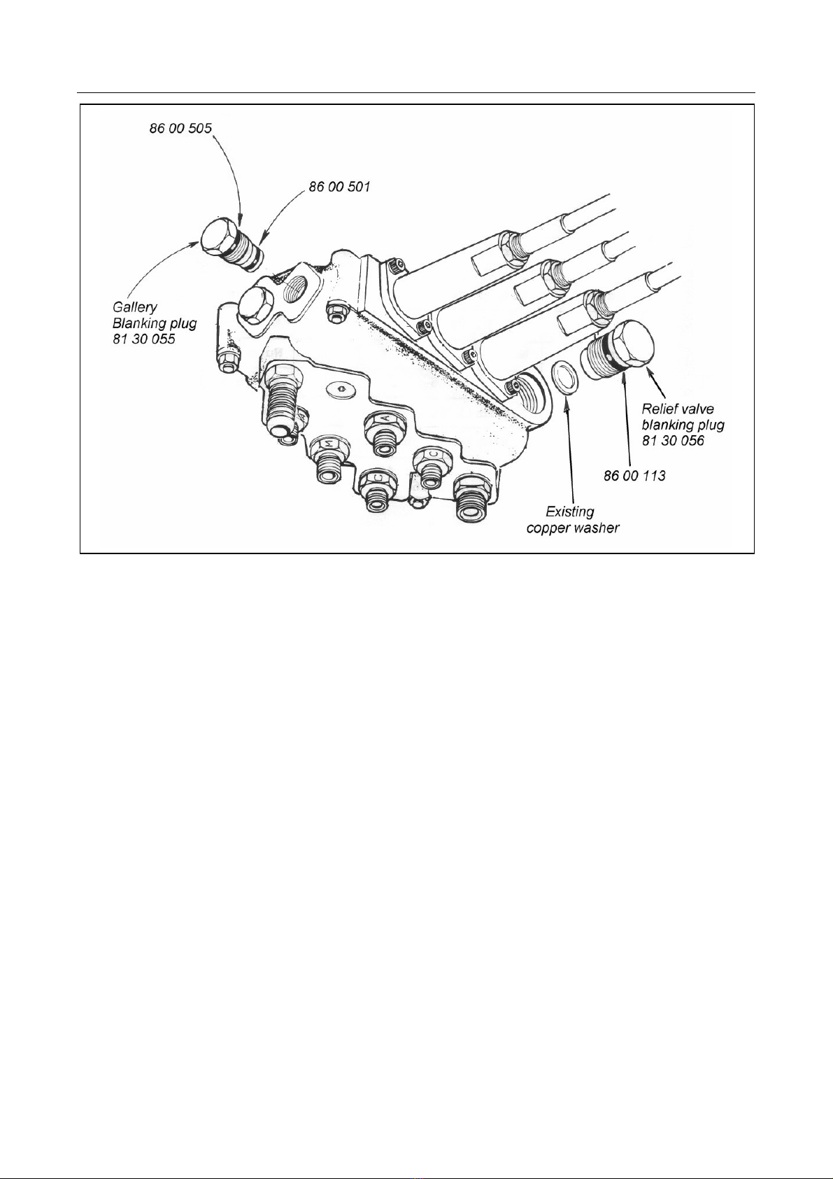
CLOSED CENTRE CONVERSION KIT (SI Models Only)
CLOSED CENTRE CONVERSION KIT 8130059 for SI models only
A control valve conversion kit (Part No. 8130059) consists of a relief valve blanking plug
which should be installed in place of the existing relief valve and a pressure gallery
blanking plug which is installed in place of the standard blanking plug at the valve outlet
end next to the lift ram gland connection.
NOTE: Care must be adopted when extracting the relief valve not to damage the copper sealing
washer as it is re-used.
When working in this mode the tractor's pressure control valve must not exceed 2500 PSI
(170 Bar).

10
OIL RECOMMENDATIONS
Tank
The machine will be delivered from the factory without oil. Fill the reservoir with light
hydraulic oil as specified in the chart below to a level approximately 3” below the top of the
tank.
The total capacity of the tank is approximately 65 Litres (14 Gallons) - Do not overfill the
tank.
Manufacturer / Supplier
Cold or Temperate Climate
Hot Climate
BP
Bartran 46
Energol HLP-HM 46 Bartran 68
Energol HLP-HM 68
CASTROL
Hyspin AWH-M 46 Hyspin AWH-M 68
COMMA
Hydraulic Oil LIC 15 Hydraulic Oil LIC 20
ELF
Hydrelf HV 46
Hydrelf XV 46 Hydrelf HV 68
ESSO
Univis N 46 Univis N 68
FUCHS (UK/Non UK
Markets*) Renolin 46
Renolin HVZ 46
Renolin CL46/B15*
Renolin AF46/ZAF46B*
Renolin 68
Renolin HVZ 68
Renolin CL68/B20*
Renolin AF68/ZAF68B*
GREENWAY
Excelpower HY 68 Excelpower HY 68
MILLERS
Millmax 46
Millmax HV 46 Millmax 68
Millmax HV 68
MORRIS
Liquimatic 5
Liquimatic HV 46
Triad 46
Liquimatic 6
Liquimatic HV 68
Triad 68
SHELL
Tellus 46
Tellus T46 Tellus 68
Tellus T68
TEXACO
Rando HD 46
Rando HDZ 46 Rando HD 68
Rando HDZ 68
TOTAL
Equivis ZS 46 Equivis ZS 68
Gearbox Oil
Check the gearbox oil level. Always check the oil with the machine on level ground, the
gearbox should be filled to a point where it is visibly level with the lip of the filler plug
aperture. Do not attempt to fill by removing the breather as the depth of the tapped thread
in the casing at this point is insufficient to allow repeated loosening and tightening of the
breather plug.
The gearbox capacity is 700 millilitres (1¼ pints) and the oil type is EP90.
11
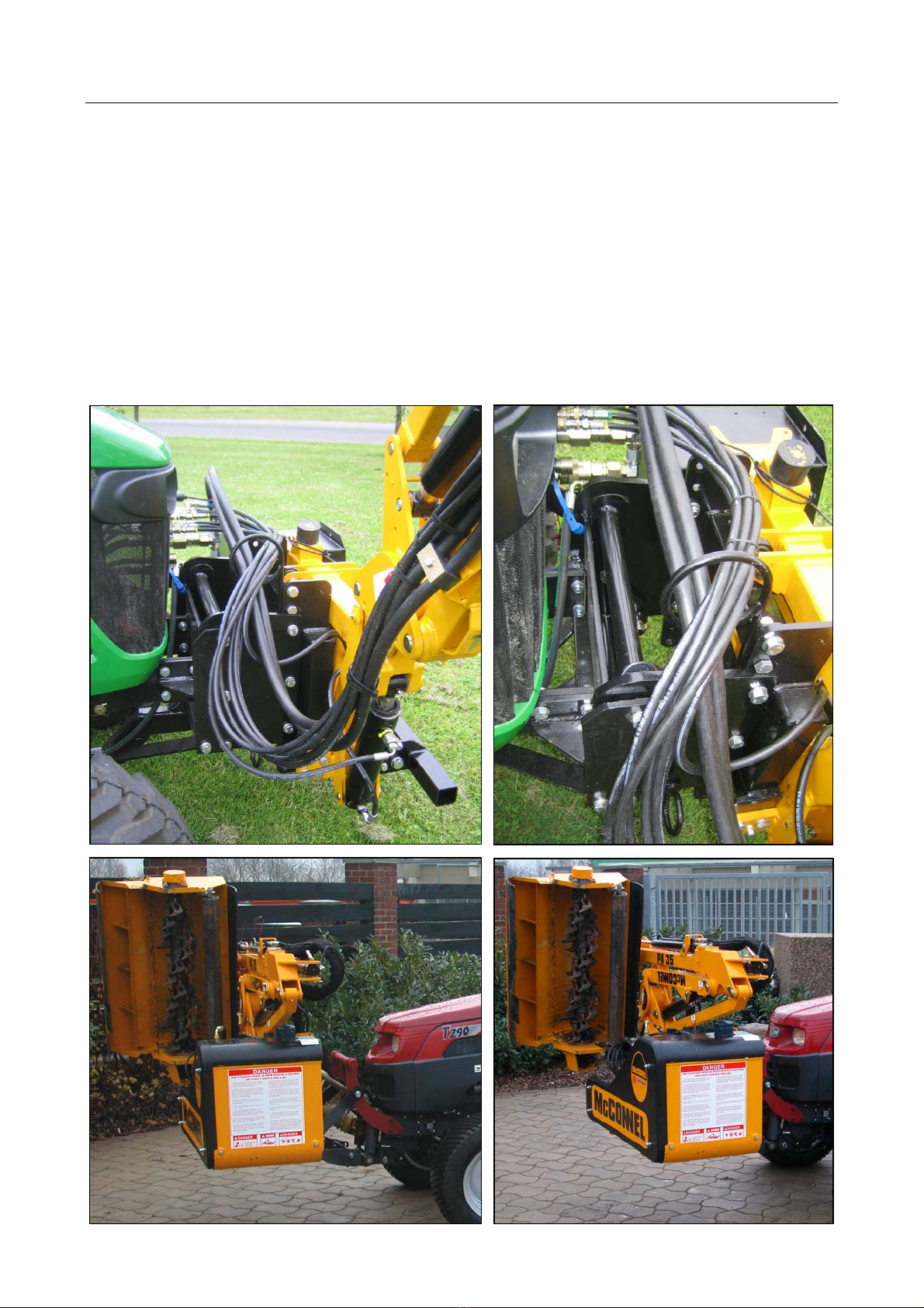
MACHINE ATTACHMENT
The PA35 is designed for front mounting on a suitable vehicle capable of carrying and
supporting its weight. Attachment fixings and attachment procedure will differ greatly
depending on the particular application and therefore cannot be illustrated here.
Whatever the particular application, the machine must be rigidly attached and safely
secured to the vehicle with the mainframe in the vertical position and the gearbox stub axle
horizontally in line with the PTO drive when in the working position. Fixings must be
capable of permitting safe attachment and removal of the machine in addition to safe
transportation and work. Wherever possible check chains and/or stabilizers should be
fitted and tightened to eliminate sideways movement of the machine.
Where any doubt exists regarding the attachment of a machine or vehicle suitability
contact the McConnel Service Dept. for advice before attempting to fit the machine.
Example Applications
12
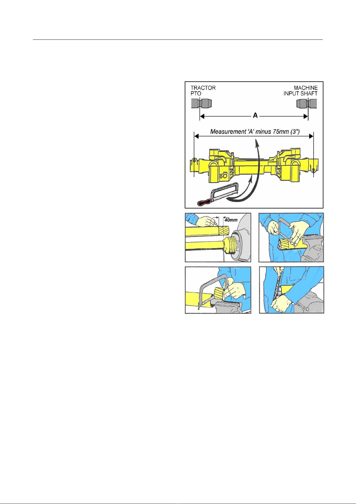
PTO DRIVESHAFT INSTALLATION
The PTO driveshaft attaches between the tractor and the machine gearbox to transfer the
power required to the run and operate the machine – it is important to achieve the correct
shaft length to avoid risk of it ‘bottoming out’ when raising or lowering the machine.
The procedure for measuring and cutting the shaft is as follows:
Measuring the PTO Shaft
With the machine attached to the tractor in
the working position measure the horizontal
distance ‘A’ from the tractor’s PTO to the
input shaft on the machines gearbox and
subtract 75mm (3”) – this figure is the
required shaft length.
Place the fully closed PTO shaft on the
ground and measure its overall length, if the
shaft is shorter than the required length you
can use it without the need to shorten -
providing it allows for a minimum 150mm (6”)
overlap when fitted.
If the shaft is longer subtract the required
shaft length plus an additional 75mm (3”) -
the resulting figure is the excess length that
will need to be removed from each half of the
shaft.
Cutting the PTO Shaft
Separate the two halves and using the
measurement obtained above shorten both
the plastic guarding and the inner steel profile
tubes of each shaft by this same amount. De-
burr the cut tubes with a file to remove rough
or sharp edges and thoroughly clean to
remove swarf before greasing, assembling
and fitting the shaft.
NOTE: For subsequent use with different tractors the shaft should be measured again to
check suitability – there must be a minimum shaft overlap of 150mm (6”).
WARNING: Always fit torque chains to the PTO shaft shields to prevent them rotating with the shaft.
This manual suits for next models
2
Table of contents
Other McConnel Trimmer manuals


