www.SteamPoweredRadio.Com
Section
2
3
4
5
6
INSTRUCTIONS
AT310
DISTRIBUTION
AMPLIFIER
INDEX
Subject
General
Description
Specifications
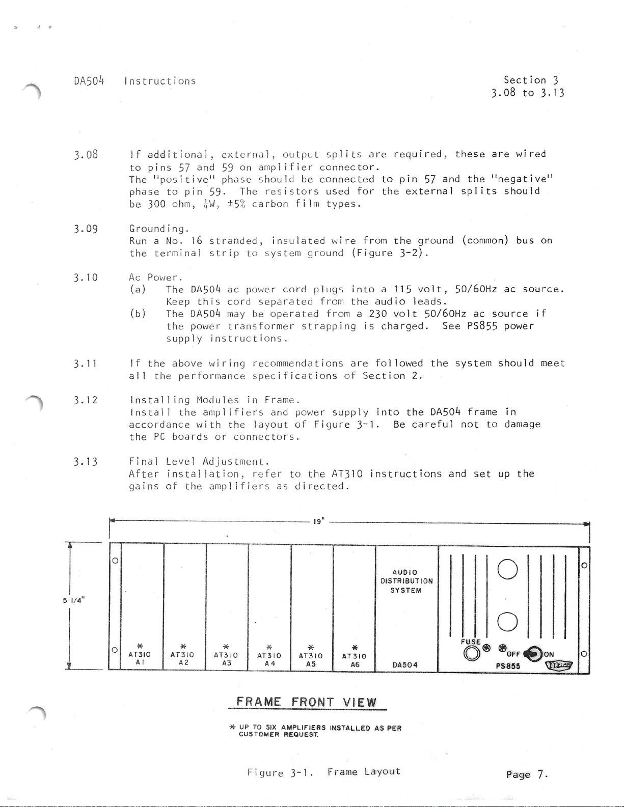
Installation
Circuit
Description
Maintenance
Parts
List
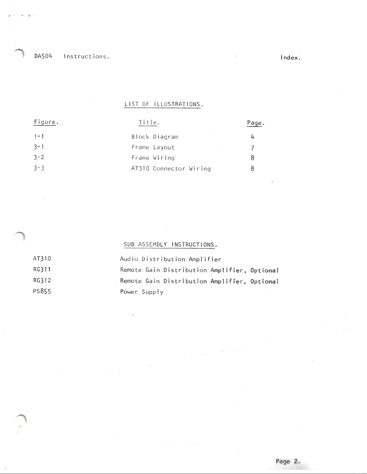
LIST
OF
ILLUSTRATIONS
&
DRAWINGS
Number
Figure
3-1
Figure
3-2
Dwg.
B-310/2-3
Dwg.
D-310/2-1
Dwg.
C-310/8-1
Dwg.
c310-30/8-1
Dwg.
B-310/1-2
Title
Connector
Wiring
Feedback
Resistor/Gain
Table
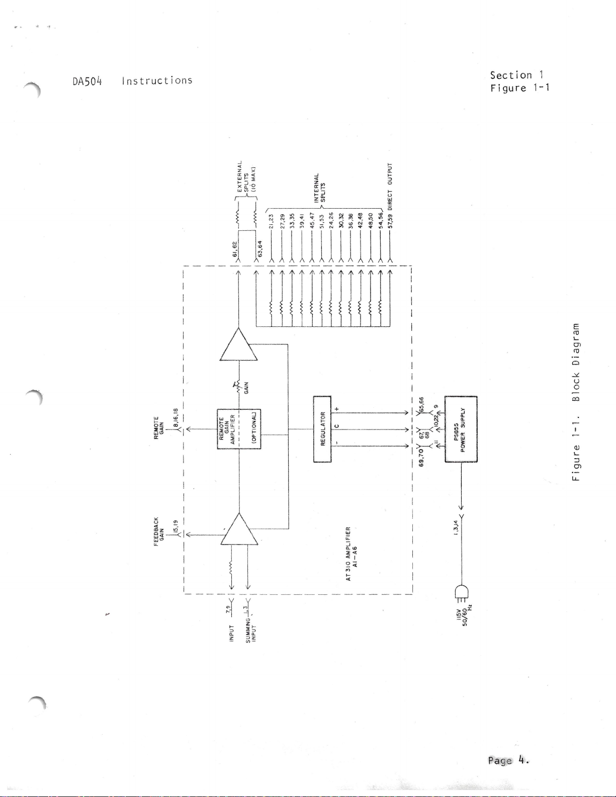
Block Diagram
Schematic
Diagram,
AT310
& AT310-30
Component
Layout,
AT310
Component
Layout,
AT310-30
Test
Setup
McCURDY RADIO INDUSTRIES LIMITED
108 CARNFORTH ROAD, TORONTO,
ONTARIO
M4A 2L4
(416)
751-6262, TELEX 06-963533, TWX 610-492-1373
McCURDY RADIO INDUSTRIES INC.
1711
CARMEN DRIVE, ELK GROVE VILLAGE, ILLINOIS 60007,
(312)
640-7077, TWX 910-222-0436
Issue
4
September,
1980
Page 1
of
17
Page
2
3
4
7
10
15
Page
6
6
8
9
12
13
14
Mccurdy
Radio Industries reserves the right, without notice
to
make such changes in equipment, design, specifications,
or
components
as progress in engineering
or
manufacturing techniques may warrant to improve the performance of the product.