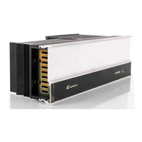
Crown D-150 User manual

D-150
SM-5
$1P1-21-0
crown
|
SERIAL
NO.
ISSUED
TO
SERVICE
MANUAL
D-150
DUAL:
CHANNEL
POWER
AMPLIFIER
~
Div.
of
INTERNATIONAL
RADIO
&
ELECTRONICS
CORP.
BOX
1000
ELKHART,
INDIANA
46514
|

Se
ome
TABLE
OF
CONTENTS
SECTION
i
INTRODUCTION
11
1.2
3
INSTALLATION
AND
OPERATION
4
CIRCUIT
DESCRIPTION
41
5
SERVICE
PROCEDURES
5.1
5.2
5.3
54
55
5.6
5.7
5.8
Scope
of
Manual
Equipment
Description
.
General
....
Unpacking
...
Mounting
Instructions
Accessory
Panel
Kit
Installation
Amplifier
Protection.
Mechanisms
Load
Protection
Methods
Operating
Precautions
...
Connecting
Output
Lines
Connecting.Input-Lines
.
Connecting
Power
..
Operating
Controls’.
Normal-Hi-Fi
Installation
Cleaning.
...
Principles
of
Operation
introduction
.....
Service
Policies
Warranty...........
Disassembly
for
Servicing
.
5.4.1.
Removal
of
Bottom
Cover,
Transformer
Cover
and
Wrap-around,
and
Board
and
Electronics
Cover
-
5.42
Removal
of
Control
Plate
Assembly...
5.4.3
Replacement
of
Components-of
Main
PC-Board,
7891
5.4.4
Replacement
of
Input
Level
Potentiometers
(R101,
R201)
5.4.5
Replacement
of
Thermal
Switch;
SW-L..
5.4.6
Replacement
of
Bridge,
DM-1
-....
5.4.7
Replacement
of
Filter
Capacitors,
C23
and
C24
5.4.8
...Replacement
of
Output-indactors;-L.102.and
k202
..
5.4.3
Replacement.of
Driver
and
Output.
Transistors
5.4.10
Replacervent
of
Power
Transformer,
11
.
Test
Equipment
000.0...
5.5.1
Calibration
of
Test
Equipme:
Test
Procedures.
Troubleshooting
5.7.1
Turr-on
Procedure
.
5.7.2
Qutput
Offset
Voltage
Check
.
5.7.3
Bias
Level
Check
0.
5.7.4
Checkout
Procedure
~
1
KHz
Input,
No
Load
.
5.7.5.
Checkout
Procedure
—
J
KM2
Input;
With
Load
5.7.6
Checkout
Procedure
—
Protection
Circuit
Tests
5.7.7
.
Checkout
Procedure
—
20.KHz
Sine
Wave
Input.
§.7.8
Checkout
Procedure
—
10
KHz
Square
Wave
input
.....
5.7.9.
Checkout
Procedure
—
IM
intermodulation)
Distortion
Test
-
5.7.10
Checkout
Procedure
~
20-20
KHz.
Hunvand.Noise
Test
....
5.7.11
Checkout
Procedure
—
Quiescent
AG
Power
Consumption
Bias
Level
Check
and
Adjustment

8
SCHEMATICS,
PARTS
LISTS
AND
COMPONENT
LOCATION
6.1
General
Information
...
6.2
Parts
Replacernent
.....
7
APPLICATION
NOTES
7.1
General
..
ae
Note
1.
v-l
Needs
of
2
Load
-
Note
2.
D-150
Morio
Conversion
..
Note
3.
PA
Adapter
Panel
installation
.
LIST
OF
ILLUSTRATIONS
DESCRIPTION
integrated:
Circuit.
Stereo.
D-150
Amplifier
D-150.
Mountinig
Dimensions’...
Panel
Kit
Mounting
Graph.
of
V-1
Operating
Range,
D-150
Output
..
Fuse
Selector
Nomiag
for
Loudspeaker
Protection:
Relay-Controlied.
Protector
With
Overload
Indicator
Peak:
Power
Limiting
Compressor
With
Qverdiive
Indicator...
Turn-On-Transient
Muter
for
Load
Protection
.
Rear View
of
Chassis
.
Seheniatic
tor-Full.
Benge.
Bectrostatic
Speaker
Connection
Schernatic
of
Ear
Phone
Pad
..
aie
Cw
OAD
Nw
om
Oo
Source
Resistance
and
Damping
Factor
¥
vs.
Length
and
‘Size
of
Output
Leads.
.
.
10
Graph
for
Selection
of
input
Capacitor
.
16
Low-Pass
Filters
for
Severe
RF
at
Inputs
..
li
Line
Voltage
Connections
(240
VAC)
~AL
Operating
Contrels
JL
Typical
Hi-Fi
Installation
....0..-
12
Test
Equipment
Complement
es
Typical
Protection
Clipping,
2-Ohm
Load
.
26
Typical
20
KHz
Sine
Wave
Test
Output
Waveform
. .
26
Typical
10
KHz
Square
Wave
Test
Output
Waveform
.
.
26
Bias
Level
Check
Components.....:
27
Schernatic
Diagrarn,
0-150
Ampiitier
.
34
Explodéd
View,
0-150
Chassis
Assanibly
33-34
Component
Location;
D150
Main.
PC
Board
7891
Exploded
View,
Contfal
Plate
Assembiy’
...
Exploded
View,
Output
Inductor
Assembly.

FIGURE
1-4,
INTEGRATED
CIRCUIT
STEREQ
2-150
AMPLIFIER
1.1
‘SCOPE
OF
MANUAL
This
matidal
is
intended
to
provide
the
User
and
sérvice
tech-
nician
necessary
technical
information
required
to
install,
oper-
ate
and
repair
the
CROWN
D-150
Dual-Charnel
Power
Amplifier
properly
and
to
maintain
the
unit
in
optirmum
operating
condition.
The
manual
is.
comprehensive;
containing
a
physical
description
of
the.0-150,
electrical
and
mechanical
specifications,
complete
installation
atid
operating
instructions,
a
detailed
circuit
descrip-
tion
and
service
procedures
to
include
troubleshooting
and
repair.
Also.
included
are.complete
parts
lists,.a
unit
schematic
and.ex-
ploded
view
drawings
to
assist
in
identification
of
parts
and
under-
standing
the
functional
operation
of
the
D-150.
amplifier.
A
thorough
reading
of
this
manual
and
strict
adherence
to
the
in-
structions,
procedures
and
cautions
will
assure
many
years
of
pro-
fessional
quality
service
and
listening
enjoyment
from
your
CROWN
D-156
Dual-Channel
Power
Amplifier.
1.2
EQUIPMENT
DESCRIPTION
Tre
0-150
isa
dual-channel
medium
power
amplifier
for
ultra-low
distortion
amplification
from
5Hz
to
20KHz
with
operation
into
loads
of
4-ohms:and
higher.
The-unit
features
extremely
tow
har:
monic
and
intermodulation
distortion,
very
low
noise,
highest
“damping
factor,”
and
quality
parts
and
workmanship.
The
unit
may
be
wired
to
produce
a
balanced
50
volt
monaural
output.
The
amplifier
is
fully
protected
against
misrretched
and
shorted
loads
by
a
resetting
V-1
(volt-ampere)
limiter
having
no
obnoxious
muting
or
program
delays.
A
thermal
switch
removes
power
from
the
unit
if
overheating
occurs
due
to
insufficient
ventilation.
The
power
supply
features
large
computer-grade
filter
capacitors
giving
over
20
joules
of
energy
storage.
A
total
of
24
discrete
transistors,
1
linear
IC
(dual
op
amp),
20
diodes
and
1
bridge
rectifier
are
utilized
in
a
CROWN-ploneered
Class
AB+B
output
circuit.
The
effective
number
of
semi-
conductors
is
40
transistors
and
30
diodes.
The
input
voltage-ampiifiers,
(IC),
are
powered
by
two
voltage-
regulated
supplies.
This
results
in
complete
channel-to-channel
isolation
and
independence
from
line
voltage
variations.
Two
level
controls
are
mounted
adjacent
to
the
inputjacks
to
allow
balancing
and
optirnizing
of
systern
levels.
ise
BRaEmnEnEgaNIRitR
ke
nsonannannsnnnnnnnssnnonimnossnnnenans

Me
Power
Output
Power
Bandwidth
Frequency
Response
LM.
Distortion
Phase
Response
Damping:
Factor
Hur
and:
Noise
Verification
Load
Impedance
Construction
input
Turon
.
Circuit
Protection
Power
Supply
Dimensions
‘Weight
Warranty
SECTION
2
SPECIFICATIONS
Power
output
not
less
than
75
watts
R.M.S.
per
channel
into
8
ohms
(both
channels
operating),
20-
20,000Hz
at
rated
distortion.
Typically
100
watts
R.M.S.
per
channel
into8
ohms,
180
watts
8.M.S.
per
charinel
into
4
ohms.
Power
bandwidth
+
1dB,
5-20,000Hz
at
75
watts
R-M.S.
per
channel
into
8
ohms.
+0.10B
20-20,000Hz
at
1
watt
into
8
ohms;
+
1dB
4-100,000Hz.
1M.
Jess
than
0.05%,
0.01
watt
to
76
watts,
60Hz
and
7,000Hz
mixed
4:1.
Harmonic
lass than
0.05%,
0.01
watt
to
75
watts;
20-20,000Hz.
+£15°,
20-20,000Hz
at
1
watt
into
8
ohms.
Gee
graphs)
Greater
than
200
orn
2676
te
1000Hz
into
8
chimes.
11008
below.75-watts:R.M.S.
output.
Each
unit
accompanied
by
its
individual
hand-entered
proof-of-perfarmance
report.
4
to
16-ohrns
(complete
stability
with
any
load);
dual
binding-post
outputs.
100%
American-made-with
industrial.
grade
construction-for
years
of
continuous
use.
Impedance
—~
Norninal
25K
ohm,
screwdriver
adjust
on
rear.
Input
sensitivity
1.2V
for
full
output.
Standard
°4”
phone-jack
on
rear.
:
J
Instantaneous,
with
no
program
delay,
and
minimum
thump.
Unique
wideband,
stable
design
utilizing
one
linear
iC
(dual
op-amp).
Total
equivalent
of
40
tran-
sistors,
24
diodes,
and
four
rectifier-diodes.
Amplitieris
short:
and
mismatch:
and
open-circuitproof.
Unique
V-1
limiting
is
instantaneous
with
no
thumps,
cutout,
ete.
Two
massive
capacitors
with
energy-storage
exceeding
20
joules.
Total
of
two
regulated
supplies
for
complete
isolation
and
stability.
No
fuses
except
AC
powerline,
17"
width,
544”
high,
9°
deep
Grom
mounting
surface).
All-aluminum
construction
with
massive
chassis,
and:
extruded
front-panel.
Amplifier
will
pane!-mount
in
a
16%"
x
5”
opening
(with
optional
front
panel).
With
adapters,
staridard
19°
rack
tieurit,
22
pounds
(24
pourids
tack
mount.
3-year
on
all
parts,
labor,
and
round-trip
shipping.

3.1
GENERAL
-
This:
section
contains:
instalistion
and
operation
instructions
for
the
D+150:
arhplifier.
Also
included:
are
destriptiaris
of
the
pro-
*
tective
mechanisms
forthe
amplifier
and
the
liad:
together
witha
list
of
operating
precautions
to
help
clarify
proper
operating
procedures.
3.2
UNPACKING
imamediately
upon:
‘peceipeot
the
‘arn
RE?
shipenenc
weber
the
unitforany
damage
incurred
intransit.
The
amplifier
was
carefully
inspected:-and-tested.
and
left
the
factory-unmarred.
Notify
the
————
comparty
immediately
ifany
damage
is
found.
Only
NOTE:
The
“basic”
D-180
shown
at
right
may
be
converted
for
rack-
or
cabinet-
(panel)
mounting
by
installing
the
front
panel
with
brackéts
or
end-caps
as
shows
below.
RACK
MOUNTING
INSTALLATION
AND_OPERATION
the
consignee
may
initiate
a
claim
with
the
carrier
for
damage
dur-
ing
shipment.
However,
CROWN
will
cooperate
fully
ini
Sich
ah
event.
Be
sur
to
Save’
thé
carton-a6
evidence
at
eerie
far
he
:
shipper's
inspaction.
CROWN
récommends
that
you
‘save
the
packing
|
materials,
even
it
the
unit
arrives
in
perfect
condition.
They
will
prove
valuable
in
preventing
damage
should
there
be
ovéas
1
Ship
the
unit.
Both
the
carton
end
internal
pack
are
specifically
de-
signed
for
protection
during
transit:
Do
not
ship
the
unit
without
this,
factory
pack”
Be
sure
to
returri
thewaerantyregistraticn
formtothe
CROWN
face
tory
within
ten
days
for
the
full
warranty
coverage.
ee
i
CABINET
MOUNTING
FIGURE
3-1.
0-150
MOUNTING
DIMENSIONS

%
The
D-150
may
be
custom
oF
rack-miounted
if
an
accéssory
front-
panel
kit
with
rack-mounting
brackets
was
purchased.
The
installation
of
this
kit
is
detailed
in
Figure
3-2.
Refer
to
Figure
3-1
for
mounting
dimensions.
Sufficient
ventilation
must
be
pro-
vided
forthe
unit.
Airmust
be
allowed
tocirculate
overthe
chassis,
atherwise.
the
amplifier.will-intenmitiently
tur
off
due
to
the
-
internal.
thermal.
protection.
feature...Applications
+-.other-than
standard
“Hi-Fi”
—
requiring
long,
sustained
signaisathigh
power
levels
may
require
the
use
of
a
cooling
fan.
3.4.
ACCESSORY
PANEL
pis
INSTALLATION
MODEL
PK)...
05
To
install
the
D-150
amplitier
ina
:
“custom
configuration’
ue
cessory
cabinet
(Model
5-D
or
5-R)
or
a
rack,
the
accessory
front
panelmust
be-attached:first:
Referto
Figure:
3:2eso2.0006
1.
Pull
four
rubber
feet
off
the
bottom
of
the
amplifier,
2.
Place
amplifier
on
bench
or
table:
stand
on
end
with
trans:
former.
down,
“Amplifier”
onthe
front
panel
should
foe
tb
cpanel
being-instalied:
sae
4.
Plastic
wedges
supplied
with
the
panel
kit
should
be
forced
inta
positions
Land
2or
Hoth
ends
of
the
unit
as
far
as
possible.
Clip
or
break
off
the
excess
part
of
the
plastic
wedges
~
5.
Align-end-caps-to-the-unit-so-holes.“A”-and
“B"
match
th
caps.
Use
6/32
x
%
socket
cap
screws.
(NOTE:
Socket
screws
may
look
as
though
they
are
cross
threading
but
willstraighten
approximately
half
way
through)
in.
a
“custom
installation”,
install
a
solid
shelf
to
support.the
amplifier..The
-shelf-top-surface
should:
be-
flush
with
the
bottom
edge
of
the
required
L6%,"
wide.x
5%"
high-panel
cutout.
When
using angle
brackets
for
rack
mounting
(Figure
3-2)
always
have
the
brushed
side
of
the
anglé-bracket
toward
you.
Simply
mount
the
end-brackets
in-place
of
the
end
caps
and
rack
mount:
as
shown
in
Figure
3-1.
FIGURE
3-2.
PANEL
KIT
MOUNTING
-on
to
Figure
2.3,
In
applications
where
the
load
is
a
loudspeaker,
amplifier
protection
will
be
evidenced
by
distortion
inthespeaker.
fatchtheend.
-
3.5
AMPLIFIER
PROTECTION
MECHANISMS
The
D-150
is
protected
against
all
the
common
hazards
which
Plague
highpower
amplifiers,
including
shorted,
open,
and
mis-
matched
loads;
overloaded
power
supplies;
excessive
temper-
ature;
chain
destruction
phenomena:
input
overiond
tetiee
and
high
frequency
overload
blowups.
é
Protection
against.
shorted
and
misrnatched-ioads
is:
‘provided:
by
an
instant-acting
Jimiter
which
instantaneously
linits
at
the
volt-
ampere
product
to
the
maximum
safe-stress.
value
eve
transistors...
“
The
area
in
which
the
amplifier
will
drive
the
load
without
being
V-i
limited
is
depicted
by
the
cross-hatched
areas
of
Figure
3-3.
if
a
load
initiates
protection
in
the
amplifi
it
can
‘be
detected
generally:
by.
watching:
the
wanster,
characteristics
ofthe
amplifier
Hy
The
audible
effect
ranges
from
something
resembling
cross-
overnatch
distortion
to
a
snapping
sound,
depending
on
the
overall
load
characteristics,
Speaker
systerns
which
are
truly
8
ohms.
or
greater
will
not
initiate
the
protection
system.
;
FIGURE
3-3.
GRAPH
of
V-1
OPERATING
RANGE
of
D-180
OUTPUT
&,
y
ea

os,
The:
AC.
line
for
120VAC
is
fused
with
a
4A,
250V.type
AG
fuse
for
240,
250VAC,
2A
type
AG).
The
use
of
any
other
type
of
fuse
will
in-
validate
the
warranty.
A
thermal
Switch
is
mounted’
onthe
Hones
10
protect
the
amplifier
against
insufficient
ventilation.
If
it
becomes
too
hot,
the
AC-line:
power
will
be
interrupted
until
the
temperature
fais
to
a
safe
level,
whereupon
power
will
automatically
be
restored.
When
such
an
event
occurs,
the’
external
symptorns
are:
no
output,
anda
wartn
anipiifier.
The
‘amplitier’s
voltage-amplifier
citcultry
is
designed
t
to.be.
in-
hereritly
current-intited.
1
any
of
the:
aevices
fail,
no
damage
occurs
to
the
rest
of
the
stages.
‘with
the
Vil
limiter,
protects
the
amplifier
foi
‘blowers
When
hod
large
RF
input
signals.
3.6"
LOAD
PROTECTION
METHODS
=
The
most
corrimon
ofall
protection
schemes
is
a
fuse
in
series
with
the
load.
The
fuse
may
be
singte;
fusin,
erallsystem.
Or,
in
the
case
of
a
multiway
speaker
system,
it
ey
‘be
rHUltiple
with
Orie
fuse
wit
éach
speaker,
SPEAKER
FIGURE.
3-4.
FUSE
SELECTOR
NOMOGRAPH
FOR
LOUDSPEAKER
PROTECTION
Fuses
help
to
prevent
damage
due
to
prolonged
Overload
,
but
pro-
vide
esseritially
no
protection
against
damage
that
may"
bé
large
transients
and
Such:
To
mininiize
this
problem,
high:
instrument
fuses
“such
“as
Little
fise
361000
Series
are’
mast
appropriate
for
siich
applications.
For
a
niomopgraph
showing
fuse
Size
¥s,
loudspeaker
ratings
refer
to
Figure
34.
;
Another
form
of
load
protector
is
shown
schematically
in
Figura
3.
5.
Whenever
the
load
is
overdriven,
a
relay
switches
a
jamp
in
Series
with
the
load;
smoothly
relieving
the’overload.
The
lamp
then
doubles
as-an
overdrive
indicator
as
it
glows:
If
overdrive
ig
unreasonably
severe,
the
lamip
will
serve
ag
2
fuse.
By
adjusting
the
relay.tension
adjustment
and
the
protéction
level
control,
this
system
is
useful
from
25
to
200
watts
for
a
typical
8
ohm
ioad.
Another
more
sophisticated
form
of
overload
protector
relieves
the
overload
by
controlling
the
ampliier’s
eu
sigral
which
is
eT
hise
; :
load:
but
also
eliminates
amplitie
possible
16
Operate
the
anipiifier
at
ids
maximum
level
with:
arain-
imum-of
chipping.
This
device
is
shown
schematically
in
Figure
3-
4,
It
features
an
overdrive
indicator,
distortionless
photo-optical
control,
and.a
Protection
Level
control
giving
adjustment
from
1W
to.
200W
when
driving
8
ohms.
.
FIGURE
3-6.
PEAK
POWER
LIMITING
COMPRESSOR
WITH
OVERDRIVE
INDICATOR

A
common
problem
which
causes
damage.and
irritation
is
the
turn-on
thump
problem
typical
to
many
signal
sources.
Figure
3-7
shows.
the
schematic
of
a
muter
which,
when.
inserted
inthe
input
signal
line,
mutes.
for
several
seconds
before
connecting
the
source
to
the
amplifier,
thereby
eliminating
turn-on
transients.
it
aiso
removes
turn-off
transients
occurring
after
the
relay
drops
See
00).
FOR
LOAD
PROTECTION
BO
this
imuter
ig
not
required.
rany
signal
source
NOTE:
When
using
the
CAO
whose
AC
power
is
switched
by
the
IC-160.
Followingare.
ey
number
of
operating
precautions
givenasanaidto
understandirig
proper-and
improper.
amplifier
usage:
1
Use
care
‘ine
taking
connections,
selecting
signal
sources,
and
Gontvalling
the
i
U
thay
bé
your
own.
CROWN
is:
‘any
damage
done
to
loads
“due
to
careless
ampliier
usage
or
deliberate
over:
powering.
For
pointers
on
load:
ibe
see
paragraph
3.6:
2)-Néver
parallel
the two
ou
OF
—
‘them
with
an
without
a
series
isglating
capacitor.
Such
operations
may
damage
the
device
and/or
needlessly
activate
the
V-Himiting
(see
Figure
3-3),
4.
Do-not
short.the.ground.
lead.of:an
output
cable
to
the
input
signal
ground
as
oscil
Fay
result
from
forming
such
a
grourid
loop...
=
8.
Operate
and
fuse
the
amplifier
only
as
set
forth
in
paragraphs
34.
6.
Operate
the
amplifier
from
AC
mains
of
not
more
than
10%
above
the
selected
‘fine
voltage
and
only
on’50,
60
or
400Hz
AG:
Falling
to
comply
with
these:
aes
will
sec
siyatate
ine
warranty.
7.
Never
connect
the
output
toa
power
supply
output,
battery;
or
power
main.
Damage
incurred
by
such
a
hookup
is
not
covered
by
the
warranty,
8.
Do
not
expose
the.
amplifier
to
corrosive
chemicals
eehs
as
soft
drinks,
lye,
salt-water,
ete.
~~
De
To
apt
rt
ecrmende
fr
ih
ower
industria
usage
at
frequencies
above
20KHz.
10,
Tampering.in.
the.
cireuit:-by
unqualified.
personnel
or
the
making
of
unauthorized
circuit
modifications
invalidates
the
warranty.
11.
Donotexpose
the
output
leads
to
areas
likely
to
be
struck
by
lightning.
Such
an:
installation,
could
invalidate
the.
amplifier.
3.8
CONNECTING
OUTPUT
LINES
input
and
output
connéctors
are
located
on
the.chassis
as
shown
in
Figure
3-8,
FIGURE
3-8.
REAR
VIEW
OF
CHASSIS
Rt
ig
always
wise
to
remove
power
from
the
unit
and
tum
the
input
level
controls
off
while
making
connections,
especially
if
the
toad
is
a
loudspeaker
system.
This
will
eliminate
any
chance-of
toud
blasts.
CROWN
is
not
liable
for
darnage
incurred
at
any
trarisducer
to
its
being
overpowered!
The
use
of
the
enclosed
speaker
fusesis
therefore
highly
recornmended:~
-
Before
making
connections,
it
is
recommnended
that
the
aperator
farniliarize
himself
wth
the
amplifiers
protective
system.
Reterence
paragraph
3.6.
Because
of
the
locations
of
the
output
connectors
(color-coded
binding
posts)
it
will
be
easiest
to
make
these
connections
first.
High-quatity,
dual
“banana”
plugs
are
the
preferred
connections
for
permanent
installations.
©

Because
the
output
wire
gauge
and
length
raises
the
resultant
source
impedance
or
lowers
the
Damping
Factor
by
adding
series:
«
resistance,
the
nomograph
(Figure..3-11)
is
provided
for
wire
selection.
For
dynamic
moving-coil
loudspeakers
the
valueRy
--
should
preferably
be.
that.
measured
by
an
ohmmeter
across
the
voice
coil,
rather
than
the
manufacturer's
rating.
For
elec
speakers
and
such,
theynanufacturér’s
rated
impedance
should
Pa
be
used
for
R,
-
ff
the
load
(matching.
teanstoriner,
inductance,
or
ibe
electrostatic
speaker
system)
appears
as
a
short-circuitatiow
freé
quencies,
a
large
non-pélarized:
capacitor’
(paralleled
with
a
resistor)-should-be-placed:in
series.
withthe.
jgad.
For
electrostatic
speakers
(if
the
manufacturer
has
not
provided
a
lar
Capacitor
oF
S90-
708
mitdand
4
ohn
power
resistor
should
be
placed
in
senes
with
the
plus
+)
speaker
lead.
This.
will
prevent
lerge
low-frequency
currents
from
darnaging
‘the:
electrostatic”
tansfortier
‘or
from
unnecessarily
activating
the
D-150's
protectivé.system.
An
effective
test
to
determine
if
such
parts
are-needed
is
to
measure
the
DC
re-
sistance
between
the
output-terminals
with
a
résistarice-is
tess
than
3
ohms,
the
parts
si
shown
schematically
in-Figare-
Ss
9.
40,200...
FIGURE
3:9.
SCHEMATIC
FOR
FULL
RANGE
ELECTROSTATIC
SPEAKER,
CONNECTION
should
nét
be
used.
A
cormmon
exariple
is
the
standard
3-
circuit
“inch
phone
jack.
and
lug
awen.
wired
-
for
stereo
sound.
.
4.
Connectors
having
low-current-carrying
capacity
are
“vers.
5.
Connectors
having
any
tendency
to
short,
or
having
shorted
leads,
are
unadvisabie.
on
Most
commercially-available-
headphones
employ
a
A-circuit
4%
inch
phone
plug
which
violates
condition
No.
2.
This
is
no
handi-
cap
if
#
pad
is
inserted
between'the
atip:
jack,
which
is
only
sensibie
when
such
a
large
amp!
is
coupied
to
such
a
small
HE
this
precaution
is
not
only
may
the
trans-
ducer
te-Gairned
out but
permanent
hearing
loss
could
result.
The
recommended
pad
is
shown
in
Figure
3-10.
“FIGURE
3-10:
SCHEMATIC
‘OF
EARPHONE
PAD
3.9
CONNECTING
INPUT
LINES
Connecting
the
inputs
will
require
observance
of
three
basic
pre-
cautions:
Undesirable
signals.to-the
inputs,
“ground
foops;“and
feedback
from
output(s)
to
input(s).
°
in
high
fidetity
audio
applications
any
good
vacuun?-tube
or
solid-
State
control
center
will
operate’successfully
into
the
25K
ohm
inputs
“of
the
D-150.
Occasionally
a
high-impedance
output
of
poorly-designed
preamps
will
be
encountered,
and/or
a
larger
_
output
coupling
capacitor
may
be
required
(o
prevent
excessive
—
fow-tr
quency
rolloff).
For.
joudspeaker-driving
applications,
the
vane
should-be
free
of
large
sub-audio
or
undesired
low
frequencies,
as
they
cause
over-
heating
and
overloading
of
the
loudspeaker.
To
remove
such
low
frequencies,
a
series
capacitor
may
be
placed
in
the
input
signal
line.
(The
graph
of
Figure
3-12
indicates
the
effectofthe
size
of
the
.
capacitor
on
the
frequency
response.
1)
Only
a
low-leakage
paper,
oF
cause
general
overload
‘sewing
-tate
stage
of
the
amip
(which
is
employed
to
provide
RF
overload
protection).
The
following
filters
are
recommended
for
such
applications
(Figure
3-13),
A
second
precaution
is
“ground
loops”
—
electronic
jargon
for
un-
desirable
circulating
currents
flowing
in
a
grounding
system.
A
commion
form
of
loop
(possibly
resulting
in
hurn
In
heoutpuld
is
a
pair
of
input
cables
whose
area
is
subjected
to
a
magnetic
hum

a8
ae
=
2.
:
RESISTANCE
DAMPING
(ohonst
FACTOR
:
100
te
Ie
cai
aes
aay
Fale
illil
ame
3
FIGURE
3-12.
'
(GRAPH
FOR
SELECTION
OF
INPUT
CAPACITOR
Ot
oe
Ry
SOURCE
inno00
8)
+
ANNEALED
gee
‘
RESISTANCE
OOF
COPPER
fohens}
2-cONnD.
300
WIRE
.
CABLE
TO
wer
gas
FIGURE
3-11.
SOURCE:
AESISTANCE
end
DAMPING
FACTOR
VS.
LENGTH.
and
‘SIZE
of
OUTPUT
LEADS
field.
in
practice
both
cables:
should,
fie:
together
along
their
minh
SUEE
ginal
Fay
Ls
MAR
EGO
A
third
precaution
(with
i
input
and
output
grounds
together,
agin
flowing
in
the
loop.
in
industrial
use,
“even
the
AC
power
line
may
provide
this
feedback
path.
Proper
grounding,
‘and
isilation
of
ih-
puis,
of-.comimon-AC-
line.
devices.is
poe
practice:
Refer:
“to,
PASE
famine
pastons,
ne
3.
10
CONNECTING
POWER
readily
av
ahs
commercially
for
adapting
this
to a
two-wire
system
if
necessary.
iat
The
‘ariplifiér
offers
two
standard
fine-voltage
connections
120
and
240
VAC.
The
tag
attached
to
the
line
cord
indicates
for
which

Because
the
output
wire
gauge
and
length
raises
the
resultant
source
impedance
or
towers
the
Damping
Factor
by
adding
series.
resistance,
the
nomograph
(Figure..3-11)
is
provided
for
wire
selection:
For
dynamic
moving-coil
loudspeakers
the
value
Ry:
«
should
preferably
be.
that.
measured
by
an
ohmmeter
across
the
voice
coil,
rather
than
the
manufacturer's
rating.
For
elect
speakers
and
such,
thenarufactuter'
s
rated
impedance
should.
be
used
for
Ry.
if
the
load
(matching,
transformer,
inductance,
or
fulbrange
electrostatic
speaker
system)
appears
as
a
short-circuit
atlow
ire
quencies,
a
large
non-polarized
capacitor
(paraticled
with
a
resistor)
should
be
placed:in
series
with
the
load.
For
electrostatic
speakers
(if
the
fnanufacturer
has
not
provided
a
capacitor)
an
external.
non:
capacitor
of
890-708
mid and
4
ohm
power
resistor
should
‘be
placed
in
series
with
the
plus
(+)
speaker:
lead:
“This:
will
prevent
=
low-frequency
currents
from
activating
the
D-150's
protective
system.
Ari
effective
test
to
determine
if
such
parts
are
needed
is
to
measure
the
OC
re-
a
meter.
{f
the
resistance
is
less
than
3
ohms,
the
parts
‘should
be
added
as
shown
schernatically
in
Figure
39,
Z
FIGURE
3-9.
SCHEMATIC
FOR
FULL
RANGE
ELECTROSTATIC.
SPEAKER.CONNECTION
“to
ba
tied
coe
durine
tiated
)
4
should
not
be
used.
A
commen
example
is
the
standard
3-
circuit
“inch
phone
jack.
and.
Plug:
when,
wired,
Aor
stereo.
4.
Connectors
having
low-current-carrying
capacity
are
“ver-
boten.’
.
5.
Connectors
having
any
tendency
to
short,
or
having
shorted
leads,
are
unadvisable.
Es
Most
comunercially-availabie
headohonee
employ
a
4-circuit
K-
inch
phone
plug
which
violates
condition
No.
2.
This
is
no
handi-
cap
if
d
pad
is
inserted
between!
@
alvip-and
jack,
which
is
only
sensible
when
such
a
large
amp
fer
i
J
transducer.
Hf
this
precaution
is
igri
;
NOt
Only
may
the
trans-
ducerbebdrned
out
but
permanent
hearingloss
could
result.
The
recommended
pad
is
shown
in
Figure
3-10.
"FIGURE
3-10.
SCHEMATIC
OF
EARPHONE
PAD
3.9
CONNECTING
INPUT
LINES
Connecting
the
inputs
will
require
observance
of
three
basic
pre-
cautions:
Undesirable
signals
to
the
inputs,
“ground
loops,
”
and
feedback
from
output(s}
to
input(s).
In
high
fidetity
audio
applications
any
good
vacuum-tube
or
salid-
state
control
center
will
operate
successfully
into
the
25K
ohm
inputs-of
the
B-150.
Occasionally
a
high-impedance
output
of
poorly-désigned
preamps
will
be
encountered,
and/or
a
larger
output
coupling
Capacitor
may
be
required
(to
prevent
excessive
low.
frequency
rolloff)..
For
cles
esosving
sulications,
the
input
should
be
free
of
large
sub-audio
or
undesired
low
frequencies,
as
they
cause
over-
heating
and-overloading
of
the
loudspeaker.
To
rermave
such
low
frequencies,
a
series
capacitor
may
be
placed
in
the
input
signal
line.
(The
graph
of
Figure
3-12
indicates
the
effectofthe
sizeof
the
capacitor
on
the
frequency
response.)
Only
a
jow-leakage
paper,
is
employed
to
provide
RF
overload
protection).
The
following
filters.
are
recommended
for
such
applications
(Figure
3-13).
Asecond
precaution
is
“ground
loops”
—
electronic
jargon
for
un-
desirable
circulating
currents
flowing
in
a
grounding
system.
A
common
form
of
loop
(possibly
resulting
in
hum
in
the
output)
is
a
pair
of
input
cables
whose
area
is
subjected
to.a
magnetic
hum
q
i
4
a
:
i
ET
|
j
H
|
:
:
3

i
Ly
eb
Ry
1OAD
Rs
SOURCE
tayio0o
fi)
+
ANNEALED
ald
a
a
:
RESISTANCE
|
DAMPING
-
RESISTANCE
000%
COPPER
fehon}
FACTOR
{ohms}
2comp.
300
WIRE
—-
cABiE
tavee)
2:
feat}
eT)
99,
‘
5
10
2
2
6
20:
1s
é
if
20
ee
:
yet
bees
ge
o
5 2
<
FIQURE3-1
1.
SOURCE
RESISTANCE
and
DAMPING
FACTOR
VS.
LENGTH
and
SRE
of
OUTPUT
LEADS
_
figid.
In
practice,
both
cables
should.
lie
together
along
their,
and
away
trom
the
power
transformer.
Tying
the
input
and
output
grou
ene
al
te
aground
loop.
3:10
connecting
POWER
The
arnplifier
is
furnished
with
a
three-wire
AC
plug
as
standard
equipment.
Adaptors
are
readily
available
commercially
for
adapting
this
to
a
two-wire
systern
if
necessary.
ae
"FIGURE
3-12.
The
amplifier
offers
two
standard
fine-voltage
Connections:
120
GRAPH
FOR
SELECTION
OF
INPUT
CAPACITOR
and
240
VAC.
The
tag
attached
to
the
line
cord
indicates
for
which
Poe

Sees”
TT
MOTE:
A
tod
teen
de
ane
10KM
aaKey,
souks
increcsad
to
5002
by
sy
auoripriate
resistor,
FREQuenct
5
FIGURE
3-12.
LOW-PASS
FILTERS
FOR
SEVERE
RF
AT
INPUTS
-
voltage
the
Sg
Gnitg
are
connected
for
120
VAC.
Figure
3-14
shows
plétarially
how
the
240.VAC
con-
hected
ufit
Should
appear.
Note
the
change
to
a
2Acline
fuse.
©
Whelt
testing’
the
‘amplifier,
the
line
voltage
miust
be
the
peak-
equivaient
to.a
sinusoid
of
the
indicated
line
voltage
when
at
full
lead.
Line
regulation
problems
can
introduce
serious
errors
inthe
~
eases
onan
amplifier
of
this.
size.
should
attempt
stration
of
the
fine
voltage
connections.
RED
BLK
wire
|.
connect
BLK-W
wire
fram
1
and
BLK
wits
from
4
to
3
on
WHY
wire
"WOVE:
ting
fuse
fe
now
ZA
~
FHGURE
3-14.
LINE
VOLTAGE
CONNECTIONS
(240
VAC}
3.11,
OPERATING
5
CONTROLS
The
-0-
150
¢
contains
all
the
facilities
essential
for
a
high
per-
formance
amplifier.
~-
The-input-controls-are-mounted-by-the
input
jacks.
Each
control
should
be
adjusted
for
the
desired
amplifier
gain
or
output
ievel.
When
the
control.is
fully.
CW,
the.
gain.is
2608.
as
Seternined
ey
precision
1%
resisiors
in
the
D-150’s
feedback
loop.
FIGURE
3-16.
OPERATING
CONTROLS
14
Hae
ER
asta
/
i

FIGURE
3-16.
TYPICAL
HI-FI
INSTALLATION
12
on
URNA
EEEtRRAanees

3.12
NORMAL
HI-Fi
INSTALLATION
1.
Two-conductor
speaker
cables
must
connect
to
the
OUTPUT
dual
binding
posts
using
terminal
lugs,
tinned
ends,
or
the
special
“banana”
plugs
supplied
with
the
D-150.
Connect
the
in-line
fuses
as
recommended
in
the
Accessory
Bag
and
Figure
3-16.
:
Since
the
D-150
is
a“basic
amplifier,“
the
main
outputs
of
the
control-center
or
“preamplifier”
must
be
connected
via
shielded
eudio-cables
to
the
two
jacks
marked
INPUT.
Use
RCA-pin.
at
preamp.
and
standard./-in.
phone-plug
at
the
D-
150.
The
two
cables
should
be
tied
parallel
along
their
entire
length
using
the
accessory
cable
ties.
.
U/L
requirements
prefer
a
3-wire
AC
power
connector;
how-
aver,
proper
Corrections
to
a
switched’
outlet
on
the
contrat
center
requires
the
use
of
a
3-to-2
wire
adapter.
NOW,
plug
the
AG:into
a
switched
outlet
on
the
contro!
center.
*
13
4.
Your
Control
Center
may
now
be
turned
on.
Then
advance
the
D-150
Input-Gain
Controls
about
4-open
(150°
clockwise).
When
using
the
CROWN
IC-150
Control-Center,
the
LOUDNESS
should
attain
almost
full
rotation
(2
to
4
o'clock)
for
loudest
“concert-hall”
volume.
If
at
3.o'clock
the
volume
is
low,
increase
the
0-150
input
gain
controls;
if
too
high,
decrease
the
0-150
gains.
3.13
CLEANING
The
CROWN
D-150
has
a
rugged
anodized
front
panet
(optional)
for
life-time
service.
The
panel
can
be
cleaned
with
a
moist
cloth
and
mild
detergent.
Never
use
steel
wool,
scouring
powder,
lye
solution,
or
arly
strong
abrasive
cleaner
as
these
will
damage
the
panel’s-tinish.
The
chassis
should
require
no
more
cleaning
than
periodic
dust-
ing
with
a
clean
dry
cloth.

4.1
PRINCIPLES
OF
OPERATION
The
D-150
has
twodirect-coupled
amplifier
circuits
which
employ
a.dual.IC
op.amp.and
silicon
transistors
in
all
anplifier
stages,
The.
CROWN-designed
and
developed
circuit
represents
a
level
of
quality
and
performance
presently
unequated
in
the
field
of
audio
amplifier
design.
Thé.
dual
1C
op
ainp
is
of
a
low
noise
type
having
a
large
gain
band-
width,
The
results
of
using
Heres
nut
eeae
real
wis
tats
record
low
values.
The
typical
full
output
(75w,
‘Bonms)
SMPTEIM
is.
0.002%..
This.
implies.
that
the.
full
power.1KHz.
THD
is
inthe
vicinity
of
0.0005%
which
is
below
the
capability
of
present
har-
monic
distortion
measurement
systems.
Multiple
feedback
loops
ara
employed
to
allow
a
Maximum
of
overall
feedback.
The
lack
of
noise
is
evidenced
by
a
typical
20Hz-20KHz
effective
input
noise
of
1-25
0
volts
which
produces
an
effective
B
ohmicut-
ut.of.
B0.micro-micro.(pica),
waits.
The.
output
stage
is
a
quasi-complimentary
format
employing
the
CROWN.
class
AB+B
technique
which
uses
no
bias
current
in
the
output
transistors.
The
result
is
maximum
efficiency
with
min-
imum
crossover
notch
distortion
and
idling
amplifier-heat.
Thus
16
SECTION
4
CIRCUIT
DESCRIPTION
there
is
no
bias
current
adjustment,
as
the
output
circuit
is
not
temperature-tolerance
critical.
inthe
new.
output
circuit,
the
driver
transistors
carry
the
bias.cur-.
tent,
while
the
output
transistors
serve
only
as
boosters.
The
out:
put
transistors
sense
wher
the
driver
transistors
are
delivering
sig-
nificarit
currentto
the
load
anc
take
over
and
deliver
the
large
load
currents.
The
output
circuit
is
protected
by
a
V-I
limiter
which
limits
the
drive
to
the
output
configuration
whenever
the
output
transistors
are
overloaded,
V-!
(volt-ampere)
limiting
Is
inherently
superior
to
all
other
forms
of
protection
as
it
directly
senses
the
overload
con-
dition
and
acts
instantly
to
relieve
the
overload,
actingonty
so
long
as
the
overload
exists,
The
result
is
Coripiéte
freedom
from
pro-
‘Star
delays
with
réliability
arid
iraximun
safe
output
power.
The
power
supply
is
a
continuous-duty
type.
The
main
OC
sup-
plies
are
full-wave
capacitor
input
type
with
a
heavy
duty
bridge
rectifier
assembly.
Computer
grade
electrolytics
furnish
over
20
joules.
of
energy.
storage.
The
D-150
represents
nothing
short
of
the
highest
quality
in
both
circuitry
and
components:
it
should
provide
a
lifetime
of
trouble-
free
service
for
the
most
discriminating
users.
,

ort,
ponent
replacement
procedures.”
Use
‘this:
information
in-con-
junction
with
Section:6,
Schematics,
Parts
Lists.
and
Component.
tocation,
to
obtain
best
results.
5.2
SERVICE
POLICIES:
Bus
to
the
sophisticated
yeuley
ont
a
fully
erty
pomneatent
service
technician
should
be
allowed
to
service
the
D-150
ampli-
fies.
User
servicing
Should
be:
confined
te
tautine
replacement
of
the
fuse
on
the
rear
panel.
Please
observe
the
following
label
on
the
rear
panel.
‘mee
ee
CROWN
0-160
ari
to
fh
tact
fore
vice,
authorization
should
be
obtained
fromthe
service
manager.
Alt
rit
pel
mcr
iether
aa
Fhig
‘warranty:does
not-extend
to.
fuses,
and/or-component
or
acu
a
Pirated
aoc
etme
damage
“Apr
application
tor
a
FREE
3-year
WARRANTY
TITLE
WS
indluded
with
the
instruction
manual
received
with
the
equipment.
Upon
Feceipt
o'
of
this
completed
tom,
CROWN.
AL
applias
tothe
original
end
-purchaser
and
will
be
issued
only
upon
receipt
of
the
application,
impertant!!
1
Note
the
following
caution
which
is
screened
en
the
amplifier
rear
panel.
CAUTION!
NEVER.
DIRECTLY.
CONNECT
The
0-150
amplifier
is
specifically.
designed
for-easy.
servicing.
It
may
be
partially
disassembled
and
stil!
-be
made
-operatiorial
for
bench
testing
and
servicing.
This
may
be
accomplished
by
re-
moving
the
bottom
cover,
transformer
cover
and
wrap-around,
and
the
board
and
slectronics:
‘cover
(para
15:
These
stans
provide
sasyaccess
to
nearly
all
n
-comiponents
of
the
amplifier.
Those
that
are
not
now
accessible
for
servicing
can
be
removed
following
the
a
eee
ee
dividual:
assemblies.
Refer-to
Figure
6-2,
1.
Remove
pee
ae
arnplifier.
moe
ree
pene
‘has
been
installed
on
the
ampli-
“frorfithe
top
of
the!
ransforner
cover
GD)
,
and
remaye
the
transformer
coverand
the
transformer
»
Wep-around
|
owes
4,
Rernove
two
screws
—e
ee
ee
tronics
cover
45).and
remove
the
cover,
5.
Reverse
the
above
sequence
of
actions.
ip
reassemble
the
amplifier.
i
ERIM
UT
RUE
aawlannasnansnasen:

Removal
of
Contre
Plate
Assembly
Reter
to
Figure
6-400
0)
:
1.
Remove
board
and
electronics
cover
as
described
in
para-
graph
5.4.1,
Step
4.
2.
Remove
two
screws
(©)
from
top
of
contro}
plate
assembly,
40951.
3.
Carefutly
lift
contro!
plate
assembly
and
turn
nearest
edge
(where.
screws
were
removed)
upward
until
bottom
of
contro!
plate
is
accessible.
Do
not
place
unnecessary
strain
on
wiring
connected
to
main
PC
board.
Refer
to
Figures
6-2
and
6-3.
1.
Remove
board
and
electronics
cover
(paragraph
5.
At,
Step).
Both
component
and
solder
sides
of
board
are
nowaccessible.
3.
The
IC
is
a
plug-in
component.
-
4.
Resistors
(R111,
R211)
(selected
bias
resistors)
aré
plug-in
§.4.4
Selaorat
of
nt
ay
Potentiometers
(R101,
R
to-terminals
of
new
input
level
6.
Pacers
new
aN
in
‘poshien
and
‘replace
contra!
nut
7.
Replace
control
plate
assembiy;
paragraph
542.
‘8:
Replace
board
arid
electronics
cover,
paragraph
6.4.1.
5.4.5
Replacement
of
Thermal
Switch,
SW-1
Refer
to
Figure
6-2.
.
Remove
bottom
cover
(paragraph
5.4.1,
Step
2).
2.
Remove
beard
and
electronics
cover
(paragraph
5.4.1,
Step
4).
Disconnect
two
Faston
connectors
@
@
from
terminais
of
thermal
switch
SW-1.
4.
Remove
two
each,
screws
Ge)
,
solder
tugs
so
the
chassis.
5.
Place
new
thermal
switch
SW-1
in-position
and-replace
hard.
ware
removed
in
Step4,
_
ad
shex
nuts
G3
,
star
washers
thermal
switch
SW-1
from
Refer
to
Figure
62.
7
1.
Remove:
trarisformer
cover
-and
transformer
wraps:
-around
(paragraph
5
4:7
“Step
3).
:
ecrrcaeh
tae
Stet
a
S
a
2
ee
@
cor
vane
dm
nt
ince
tint
igs
DEA
position
and
replace
hardware
ré-
moved
in'Step
4.
6.
Recorinect
four
Faston
¢
connectors
(19)
_)
@
to
terminals
of
bridge
OM
I.
Ve
Replace
bottom
COVEr
w(patigrochvbd:
1,
Step
2).
4.
Remove,
bad
8.
Replace.
“transformer
‘cover
and
‘transformer
wrap-around
(paragraph
5.4.1,
Step
3).
Refer
to
Figure
6-2.
1:
Tessie
bation
cove
<paraieph
6.4.2,
Step
2).
2.
Remove.
transformer.
cover.
and
‘transformer
wrap-around
(paragraph
5.4.1,
Step
3).
3.
Remove
ene
Faston-cannector
@.
Bt
fromm
filer
capacitor
(C23
er
C24)
terminal.
J
RRR

Ne
twopanel
washers
4.
Remove
twoscrews
(7),
one
solder
tug!
from.
ie
filter
@)
(8)
and.
two
fiber
shoulder.
washers.
capacitor
terminals.
5.
Remove
defective
iter
capacitor
(C23,
or
24)
from
the
chassis.
6.
ae
eter
capac
poston
and
replace
harder
..
removed
in.
Step
4.
.
7,
Réconnect
Faiton
connector
®
@
to
fier
capacitor
terminals.
8.
Replace
transformer
cover
and
transformer
wrap-around
“(paragraph
5.4.1,
Step
3).
9.
Replace
bottom
cover
(paragraph
§
4.1,
step).
5.4.8
Replacement
of
Output
Inductors,
Replace
and-L202
Referté
Figure
65.
om
cover
(paragraph
6.4.1,
Step
2),
2.
Remove
board
and
electronics
cover
(naragraph
54.1,
Step
4).
_
3.
Unsoler
one
end
of
brown
collwire
(2)
from
the
output
bind-
‘ing
post
terminal
eS
a
driver
transistor
terminal.
.
2
hex
nut
7),
star
washer
(6)
vaper®
output
coil
toroid
core
and
brown
wire
C1)
5.
Place
‘ew
‘output
Coll
toroid
core
and
new
brown
wire
in
position
and.
replace
hardware
removed-in
Step
4:
6:
Soldier
ong
ene
sf
brown
coil
witeQ
to
the
output
Binding
post
terminal
and
the
other
,
Snd-to
the
adjacent
driver
transistor
tarininal:
7.
Replace
boarcl
and
electronics
cover
(paragraph.
4.
1,
Step
4).
_.8..
Replace
bottom
cover
(paragraph
5.4.1,
Step
2).
Refer
to
Figure
6-2.
ds
Remove
bottom:-cover
(paragraph:
5.4.1,
Step.
4
frie
ies)
Gtr
noe
as
een
a
:
.Mlove
hardware
shown
and
the
defective
tra
transisior
Case
and
the
chassis
wih
a”
Thedt-condcting
compound
(06-340).
9
6.
Install
new
transistor
and
tighten
a
ai
assure
good
heatsinking.
7.
Resolder
wires
and
corriponent
feeds
te
femoved
from
transistor
terminals
in
Step
3
above.
8.
Replace
board
and
electronics
c
cover
er
(paragraph
54.1,
step4).
9.
Replace
bottom
cover:
(paragraph
5.4.1,
Stap.2).
5.4.10
Replacement
of
Power
Transformer,
T-1
1.
Remove
bottam
cover
(paragraph
5.4ck,
Step
2)
or
Be
Penis
Neate
ee
“Over
an
Seanetorneer
wrap-around
‘(Paragraph
5.4.1,
Step.
3).
3.
Desi
cei
trailor
nae
wat
pas
through
the
ee
calalne
iia
salloh
coenentoes
edie
DML:ter.
“ninalsandremove
Faston
connectors:
>
@
fromthe
red
wires.
b.
One
yellow
wire;
unsoiderfrom
solder.
tug(@)atiunction
‘of
capacitors.C23.and.C24..
¢
One
black
and
one
white
wire;
unsolderfromterminal
strip
d..
One
black/red
wire
agd
one
black/white
wire:iunsolder
__:
from
terminal
strip
i
4,
Pull
alt
wires
back
through
hole'in
chassis:
§.
Remove
hardware:
securing
transformer-T1.to
the
chassis.
2
—
=
7
Cut
feads.on
ou
Unestsenar
Ti
tosame
ene
as
those
on
the
transformer
being
replaced.
r
8.
Place
new
banstonmer
TE
pil
iad
ha
hes
10.
Connéet
|
seven
transformer
wires
to
destinations
shown
in
Step
3,
7
é
transformer
cover’
arid
tansformer
Wrap-around
(paragraph
6.
4,
1,
Step
3).
12.
Replace
bottom
cover
(paragraph
$41;
Step
2)
Other manuals for D-150
4
Table of contents
Other Crown Amplifier manuals

Crown
Crown CTs 4200 User manual

Crown
Crown BCA Manual

Crown
Crown FM2000A User manual

Crown
Crown CTS SERIES CTS 3000 User manual

Crown
Crown XLS 202 User manual

Crown
Crown DC-300A User manual

Crown
Crown PS-400 User manual

Crown
Crown I-Tech HD Series User manual

Crown
Crown Macro-Tech MA-600 User manual

Crown
Crown CTs 4200 USP/CN User manual

Crown
Crown PowerTech PT 3.1 User manual

Crown
Crown DSi 4000 User manual

Crown
Crown CE-2000A Manual

Crown
Crown CTs 1200 Manual

Crown
Crown CDi 2000 User manual

Crown
Crown XS900 User manual

Crown
Crown CDi 1000 User manual

Crown
Crown DSi 1000 User manual

Crown
Crown D-150A User manual

Crown
Crown CMA-1 User manual