Mclane Throw Reel Mower User guide

20"
25" MCLANE MOWER
Owner' Handbook Front
Throw Reel Mower
CONTENTS
Page
2
3
4-6
7-10
12-14
13-14
11
Safety Rules
Front Throw Reel Mower Features
Assembly Instructions
Operation and Maintenance
Lawn Mower Parts Illustration
Lawn Mower Parts List
Trouble Shooting
i 7110 East Rosecrans Ave.
_Paramount, CA 90723
_" Telephone
z(562) 633-8158 (213) 636-8336

Training
Preparation
Operation
Maintenance
and Storage
SAFETY RULES
1. Readthe Operating and Service Instruction Manualcarefully. Be thoroughly familiar with the controls and
proper useof the equipment.
2. Neverallow children to operate a power mower.
3. Keepthe area of operationclear of all persons,particularly small children and pets.
,
.
3.
,
5.
6.
7.
Thoroughly inspect the area where the equipment is to be used and removeall stones, sticks, wire, bones
and other foreign objects.
Donot operateequipment when barefoot or wearing open sandals.Always wear substantialfootwear.
Checkfuel before starting engine. Donot fill gasoline tank indoors,when engineis running,or while engine
is still hot. Wipeoff anyspilled gasoline beforestarting engine.
Disengageself-propelled mechanism or drive clutch on units so equippedbeforestarting engine(motor).
Neverattempt to make a wheel height adjustment while engine (motor)is running.
Mow only in daylight or in good artificial light.
Neveroperateequipment in wet grass.Always be sure of tourfooting; keepa firm hold on the
handleand walk, neverrun.
,
2.
3.
4.
5.
,
7.
8.
9.
10.
11.
12.
Donot changeengine governorsettingsor overspeedengine.
Donot puts hands or feet near or under rotating parts. Keepclear of dischargeopening at all times.
Stop blade(s)when crossing graveldrive, walks or roads.
After striking a foreign object, stop the engine (motor), removewire from spark plug, thoroughly inspect the
mower for any damage, and repair the damage before restartingand operating the mower.
If the equipment should start to vibrate abnormally,stop the engine (motor) and check immediately for the
cause.Vibrationis generallya warning of trouble.
Stop engine (motor) whenever youleavethe equipment,before cleaning mower housing,andwhen making
any repairs or inspections.
Whencleaning, repairing or inspecting,make certain blade and all moving parts have stopped. Disconnect
spark plug wire and keepwire away from plug to prevent accidental starting.
Donot run engine (motor) indoors.
Shutengine (motor) off and wait until blade comesto a completestop beforeremoving grasscatcher and/or
uncloggingchute.
Mow across the face of slopes, never up-and-down. Exerciseextreme caution when changing direction on
slopes.Donot mow excessivelysteep slopes.
Neveroperate mower without proper guards, plates or other safety protective devicesin place.
Keepwashoutports and othermower housingserviceopeningsclosedwhen mowing.
1. Checkblade and engine mounting bolts at frequent intervals for proper tightness.
2. Keepall nuts, bolts,and screws tight to be sure equipment is in safe working condition.
3. Neverstore equipment with gasoline in the tank insideof a building where fumes may reachan open flame
or spark.Allow engineto cool beforestoring in anyenclosure.
4. Toreducefire hazard keepengine free of grass, leavesor excessivegrease.
5. Checkgrass catcher frequentlyfor wear or deterioration.
TWO YEAR LIMITED WARRANTY
For two years from purchase (60 days for commerciat use) McLane Manufacturing Inc., will replace for the odginaI purchaser, free of charge, any part or parts, found upon
examination by any factory authorize service center, or by the factory in Paramount, California, to be defective in material or workmanship or both, All transportation charges
on parts submitted for replacement under this warranty must be borne by purchaser, There are no other expressed warranties. Implied warranties, including those of
merchantability and fitness for a particular purpose, are limited to two years from purchase and to the extent permitted by law Any and all implied warranties are excluded. This
is the exclusive remedy and liability for consequential damages. Any and all warranties are excluded to the extent exclusion is permitted by law. Some states do not allow
limitations on how long an implied warranty lasts, and some states do not allow the exclusion limitation of consequential damages, so the above limitation and exclusion may
not apply to you, This warranty gives you specific legal rights and you may also have other rights which vary from state to state. It is your responsibility to follow the maintenance
instructions described in the owner's manual. Routine service (cleaning, blade sharpening) is your responsibility. Defect of engine is covered by manufacturer of engine.
McLane Manufacturing, Inc.
Note: Operator abuse and improper assembly of product is not covered by any written or implied warranty. Read your owner's manual carefully
2

Manual Drive Lever
\
Drive Control
Rod
Throttle
EngineClutch
Lever
Notice to customersin the State of California.The
engine on this units is not equipped with a spark
arrestingmuffler.
--WARNING---
USEOR OPERATIONOF THIS ENGINEON ANY FORESTCOVEREDIBRUSH
COVEREDtOR GRASS COVEREDLAND WITHOUT A STATEAPPROVED
SPARK ARRESTOR IN EFFECTIVEWORKING ORDER CONSTITUTESA
VIOLATIONOFTHE LAW OF THESTATEOFCAUFORNIA.
Upper Clutch
Control Rod
Throttle Wire
1/4"x 7/8"
Air Cleaner
Cutting Height
Adjustment Lever
Lock Nut
Lower Clutch
.,e_ Control Rod
Belt Guard
\Reel

ASSEMBLY
TOOLS REQUIRED: 7/16" Wrench, Pliers, Screwdriver (11/16" Wrench needed to adjust Clutch Tension)
NOTE: Reference to left or right side
of the mower is from operator's
position at the handle, facing fonNard.
The lawn mower is fully assembled
except for the handle throttle control,
drive control rod and clutch control
rod. Everything is packed and shipped
in one container.
ASSEMBLY:
1. CARTON REMOVAL
Cut the back panel, lay down pull
mower backwards.
2. PARTS ID
3. TOOLS REQUIRED
7/16" Wrench, Pliers, Screwdriver
(11/16" Wrench needed to adjust
Clutch Tension)
STEP 1: Remove the grass catcher,
handle assembly, and rodsfrom the box
(see Fig. 1, grass catcher not shown).
STEP 2: Attaching the handle: remove
the bolts retaining the panel to the lower
handle. You need six bolts to mount the
handle. Two of the six bolts were those
you just removed. The other four are
supplied with loose hardware in the
plastic bag. (see Fig. 2) Take the bottom
section of the handle (Fig. 3) and install
a bolt through the brace, the upper
handle section, and the panel or
bracket. Put a nut on each bolt and
secure the panel or bracket on both
sides of the handle.
NOTE: The three holes in the upper
handle must be aligned with the three
holes in the lower handle. The handle
brace is put on the outside of the
upper handle. Slip on the handle
grips. Soaking in hot water may ease
assembly.
DRIVE CONTROL ROD ASSEMBLY:
(see Fig. 4 & 5)
1. Assemble drive control rod (one
piece rod with both ends bent), by
inserting one bent end in the drive
control lever bearing and inserting
the other end in the drive pivotrod.
2. Secure the control rod with cotter pins.
ENGINE CLUTCH CONTROL ROD
ASSEMBLY: (see Fig. 6)
1. The clutchcontrolrodconsistsof one
long rod with one bent end, one
coupler, two lock nuts and one short
rod with one bent end.
2. Assemble the clutch control rod by
inserting the short rod bent end in the
clutch bearing. The end of the rod
must be outside the belt (Fig. 6).
3. insert the bent end of the long rod
in the clutch lever bearing.
4. Insert a cotter pin in each bent end,
but do not secure until final
adjustment is made.
IMPORTANT! ENGINE CLUTCH ROD
TENSION ADJUSTMENT: (Fig. 7)
1. Lift the engine clutch lever to the
handle. If there is a slight tension on
the belt, the adjustment should be
correct. The tension should be just
enough to propel the mower and reel
without the belt slipping on the pulley.
EXCESSIVETENSION WILL REDUCE
BELTLIFE AND PERFORMANCE OF
THE MOWER.
2 Check for correct belt tension"
CAUTION !
A. Remove spark plug wire, engage
the clutch by lifting the clutch
lever to the handle and pull on
the rope starter.
B. Ifthe reel turns, the tension should
be correct, however, be sure to
check if the idler bearing is putting
excessive tension on the belt.
C. If reel does not turn, more tension
is needed. Final adjustment can be
made after reel is operating.
3. ADJUSTMENT PROCEDURES:
A. Excessive Belt Tension: Remove
the upper rodfrom the clutchlever
handle and turn right (into the
coupler)one turnat atime untilthe
tension is correct.
B, Increased Belt Tension Needed:
Remove the upper rod from the
clutch lever handle and turn left
(out of the coupler) one turn at a
time until the tension is correct.
C. When the tension is correct, insert
the upper rod into the clutch lever
handle, secure the cotter pins at
both ends of the control rod and
tighten the lock nuts to the coupler.
At this time, replace the spark plug
wire.
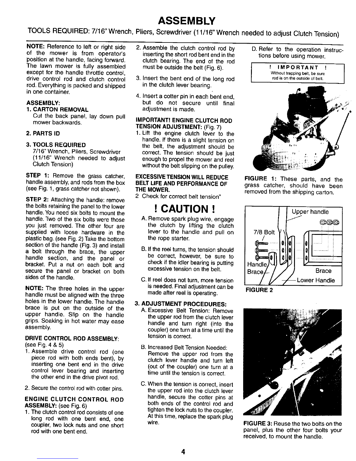
D. Refer to the operation instruc-
tions before using mower.
f IMPORTANT !
Without trapping belt, be sure
rod is on the outside of belt.
FIGURE 1: These parts, and the
grass catcher, should have been
removed from the shipping carton.
Upper handle
/f
7/8 Bolt _ _\ /3 i :
Ha_ ......
Brace_-// ;Brace
/_/" 7 -- Lower Handle
FIGURE 2
FIGURE 3: Reuse the two bolts on the
panel, plus the other four bolts your
received, to mount the handle.
4

ASSEMBLY
RGURE 4: InstalltheWheel Drive Controlrodon topand insert
cotterpin.Then, openitsbottomtosecurelyfastenit. RGURE 7: Putthebentend oftherodthroughthe holeofthedrive
dutch lever.
INSTAWNG THROTTLE CONTROL:
1. One end of the throttle control is factory installedto the
carburetor.The other end needs to be installedin the upper
handle.
2. Take hold of thecontrol leverat the otherend ofthe cableand
route the throttle cable under and behind the panel located
where the upper handle is boltedto the Ic_,_rhandle.
3. See Fig.8:Holdthe control leveratthe end ofthe throttlecable
and twist itslightlyso the knob will pass through the slot in the
upper handle.
RGURE 5: Insertthe red at the bottom of.theWheelDrive Lever
andsecurewithacotterpin.
Clutch
aring
FIGURE 6: PUtthe bend end of the rodthrough the bole ofthe
idlerbracket.Secure laterwitha cotter pin.
5
FIGURE 8: Twistleverso knob will passthrough slot in panel.

THROTrLECONTROLASSEMBLY:
1.SeeF_j.9:When the knobisthrooghthe
handle panel, straighten the throttle
cable sothe throtttecontrol body can be
pushed through the panel slot.
SIDE VIEW
RGURE 9
ASSEMBLY
3. See Fg. 11:Une thecempleteknoband
control body unitwith the panel slot.Use
bothhandsand pushthecontrolbodyunit
intothepanelslot untilitlocksinplace.
FUELAND OIL
NOTE: EngineisshippedWITHOUToil.Use
ahigh quality detergent oil classified "for
serviceSF,SE,SDor SC".30 or 10W-30wt
oil is recommendedfor mcet areas.Do not
use 10Wt- 40Wtoil.
TO FILLCRANKCASEWITH OIL
Placeenginelevel.Clean area aroundoil fill
beforeremovingoilfillplug.
OILRLL PLUG
Removeoilfillplug.Fillcrankcaseto pointof
overflowing. POUR SLOWLY Capacity
approximately20ounces.Replaceoilfillplug.
.4L CAUTION .4L
Handle fuel with care - it is highly
flammable. Use only approved fuel
container.Neveradd fuel whileengine is
running. Fill fuel tank outdoors with
extremecare.Neverfillfuel tank indoors.
Replacegasolinecap securelyand wipe
upall spilledfuel.
2, See Fig. 10: Push entire knob and
control body throughthe panel slotfrom
the back as shown.
FIGURE 10
RGURE 11
INSTALLING GRASS CATCHER:
1. See Fig. 12:Loosen catcher hook, nuts
and bolts. Remove front nut and bolt
from each catcher hook. Then raise
catcher hooks and fasten both hooks
with the bolts. Leave bolts loose until
catcher is adjusted for proper clearance
from the reel I_ades.
,Attach grass catcher to the mower and
make sure the catcher does not touch
the reel blades. The catcher hooks are
slotted so you can easily adjust the
catcherso itwillclearthe reel blades.
3. When proper clearance is assured,
tighten _',e nuts and _ holding the
hooks to the catcher.
TO
RGURE 12
We recommend the use of clean, fresh
Icad-freeges_ine. Leadedgasolinemaybe
usediflead-freeisnot available.A minimum
of 77 octane is recommended.The use of
lead-freegasoiineresultsinfewercombustion
depositsandlongervalvelife.
NOTE:We DONOT recommendtheuseof
gasoline witch contains alcohol, such as
gasohol.However,ifgasolinewith alcoholis
used, it MUSTNOT contain more than 10
percentEthanoland MUSTberemovedfrom
theengineduringstorage.
DONOT use gasolinecontainingMethanol.
See STORAGEINSTRUCTIONS
WARNING: Experience indicates that
alcohoiblendedfuels (calledgasoholorusing
ethar_olor _noi) can attract rce_-_e
which leadsto separationand formationof
acidsduringstorage.Aciditygascandamage
thefuelsystemof anenginewhilein storage.
To avoid engine problems,the fuel system
shouldbe emptiedbeforestoragefor30 days
or longer.Drainthegastank,starttheengine
andletit run untilthefuelline andcarburetor
are empty.Use fresh fuel nextseason.See
StorageInstructionsforadditior_ information.
Never use engine or carburetor cleaner
products in the fuel tank or permanent
damagemayoccur.
_DONOT fill fuel tank to point of
overlfowing.Provideapproximately1/4"
oftank spaceforfuelexpansion.
6

OPERATION
cu'n'ING HEIGHT ADJUSTMENT
The cutting height isadjustable from 1/4" x 1-1/2". The front
wheet assembly bar may be moved in 3-holes on the side
panels to adjust the height. (Refer to FIG. 13) The two top
cutting height adjustment holes, A & B are used for all
height adjustments except for the 1-1/2" height. Hole Cis
only used for the 1-t/2"' adjustment.
Cutt_
A. 1/4"-11/16
F o/
Figure 13
Lift lever as shown (Fig 14) and adjust height by
repositioning notched bracket.
Rear Axle Positions
o.
Figure 14
LEVER POSITION
SCALPINGNotch No. 1
Notch No. 2
Notch No. 3
Notch No. 4
Notch No. 4
HEIGHT
A B C
1/4" 7/8" i
7/16" 1" --
5/8" 1-1/8" --
1-1t16" 1-3/16" --
-- -- 1-1/2"
NOTE:
When using A or B hole in the side panel (Fig.13) the
notched lever (Fig. 14) must be changed to A or B hole
also. When using the C hole in the side panel, place the
notched adjusting lever in the B hole.
REAR AXLE ADJUSTING:
The rear axle height positions my be changed by the
mower owner, however, due to the mechanics involved it is
recommended the procedure be done by an Authorized
McLane Service Center.
The mower is shipped with axle in the middle position and
the cutting heights listed above are achieved with the axle
in this position. The rear axle must be lowered to the high
position (Fig. 14) to achieve the 1-1/2" cutting height.
REAR AXLE ADJUSTING INSTRUCTIONS:
1. Drain the gas and oilfrom the engine. Turn mower so the
front wheels and the engine are resting on the gournd or
work benchtop.
2. Refer to Fig. 14A
A. Remove chain guard-No. 20
B. Remove side plate chain-No. 21
C. Remove clutch drive chain-No.15 and add (2) chain
links. They can be purchased from the factory or
McLane Service Center. Part No. 5016
D. Remove (8) retainer bolts-No.12
E. Loosen (8) hanger bolts-No. 13
3. Move Axle outward until retainer bolt hole aligns with the
high hole in the side plate. (Fig. 14)
4. Replace and tighten (8) retainer bolts.
5. Tighten (8) hanger bolts.
6. Replace side plate and clutch drive chains.
7. Refill oil and gasoline.
12
8
7
49
2
Figure 14A
7

OPERATION
CAUTION: To avoid possible damage to front wheels do not start
mower beforesetting height adjustment.Notched heightbracketat
right front of mower (Fig. 14) must be placed at desired cutting
heightposition.
HOWTO USEYOUR MOWER
THROTTLE CONTROL:
Theenginespeediscontrolledbythethrottleleverlocatedatthetop
ofthehandle.The leveralsocontrolsstarling and stopping.
DRIVE CLUTCH LEVER:
Thisleverislocated onthe left sideofthemower and when raised,
engages the clutchwhich drives the reel.Forsafety,when thelever
is released,the reel and mowerstops immediately.
MANUAL DRIVE LEVER:
The drive lever is located on the rightside of the handle. When
pushedforward thednvewheel engages theground and drives the
mower.Activated the clutch leverfirst, thenthe driveleverto propel
mower forward.
STARTING THE ENGINE
1. Before starting refer to engine manual for detailed engine
manufacture'sinstruc_ons
2. Move engine choke leverto choke position.Pull rewind starter
handle rapidly, repeat if necessary. Move throttle down to
running position.
3. Lift engine clutch control and hold against handle to engage
reel(Fig. 15).
4. Move drivecontrol to DOWN positiontomove forward.
5. Todisengage reel drive, immediately releasecontrol lever.
6. Tostop enginemove throttle levertoSTOP position (Rg 15).
HOW TO USE THE CONTROLS AND
WHAT THE CONTROLS DO
1. From the operators position which is behindthe lawn mower,
engagesthecuttingblade.
2. The control in the middleregulatesthespeed oftheengir_e.
3. The control lever on the right engages the self-propelled
mechanism.
TURN THE PRODUCT OFF
1. The Engine--push the middle control all the way towards
operatorto stop.
2. Cutting Blades---releasethe handle on the leftside.
3. The Self-PropelledMechanism---release the handle on the left
side also.
CAUTION
The Operation of any lawn mower can result inforeign
objects thrown into the eyes, which can result in
severe eye damage. Always wear safety glasses or
eye shields before starting your lawn mower and while
mowing.We recommend Wide Vision Safety Mask for
over the spectacles or standard safety glasses.
Drive
Control
\
Figure 15
Throttle
(Mowing speed Control)
I
I
Engine
Clutch
CAUTION
Before starting engine, become familiar with all
controls. Read this Operator's Manual thoroughly.
Always check engine oil level before starting engine.
CAUTION
Care should be taken to avoid inhaling exhaust gases
as they contain carbon monoxide gas which is
colorless and odorless. Carbon monoxide is a
dangerous gas that can cause unconsciousness and
is potentially lethal. Do not runengine in confined areas
such as a closed garage.
8

MAINTENANCE
GENERAL RECOMMENDATION
1. The sparkplug and air filtershouldbe
replaced once a year. This will assure
better engine performance and longer
engine life.
2. Checkall fastenersand be suretheyare
tight.
3. Follow all maintenance instructions
listed on the following pages an the
service schedule.
A CAUTION A
DISCONNECT SPARK LUG WIRE FROM
SPARK PLUG AND PLACEWIREWHERE
iT CANNOT COME IN CONTACT WITH
SPARK PLUG.
AIR CLEANER
MUFFLER
o...,#io, eAi.
COVER OIL RLL PLUG
OILLEVER
FIGURE 16
CHANGING ENGINE OIL
1. "_ltmowerhack,placesuitablecontainer
on floornexttodrive wheel.
2. Placea pieceofmetal overdrivewheel
so oilwilldrain intosontainer.A plastic
funnel can also be used. Cut part of
funnel away and place under drain plug
making sure small end of funnel is
directedtowardthe container.
3. Remove oil drain plug.(Referto Fig. 16).
4. When oil is drained, replace plug and
refill crankcase with oil as per
instructionson page 7.
TO SERVICE AIR CLEANERS
Clean cartridgeatthree monthintervalsor
every 25 hours,whichever occursfirst.
NOTE: Serwe more often ifnecessary.
1. Remove knoband cover.
2. Remove carlddge by pulling it off of the
screw.
3. Cleanby tappinggenT on aflatsurface.
Ifvery dirty,replacecartridge or cleanas
follows:
a. Wash in a low or non-sudsing
detergent and warm water solution.
CALmON: Do not use petroleum
solvents such as kerosene,to dean
cartridge.
b. Rinse thoroughly with flowingwater
from insideout untilwater isdear.
¢. Allowcartridge to stand and air dry
thoroughly beforeusing.
DO NOT OIL CAR'R:IIDGF..
DO NOT USE PRESSURIZED AIR
TO CLEAN OR DRY CARTRIDGE.
4. Installcartridge, then cover and screw
knob securely.See F_jure17.
KNOB.---.----,',_
CARTRIDGJ
BASE PLATE
GASKET _
CARTRIDGE
RGURE 17
SPARK PLUG
Clean and reset gap at .030" every 100
hours ofoperation.
CLEAN COOUNG SYSTEM
Grass, chaffor dirt may dog the rotating
screen and the air cooling system
especiallyafter prolonged service cutting
dry grass. Yeady or every 100 hours,
whichever occurs first, remove the blower
housing and clean the areas to avoid over
speeding, overheating and engine
damage. Clean mere often if necessary
REfer to Engine manual for detailed
instructions.
CLEAN ENGINE
Remove dirt and debris with a cloth or
brush. Cleaning with a forceful spray of
water isnot recommended as water could
contaminate the fuel.
9
LUBRICATION
Check oil level regularly.Oil all exposed
bearings,linage andfront wheels.Oil chain
frequently. Reel and main drive bearings
are sealed.
REEL MAINTENANCE
Normally grinding of" the reel is not
recommended or necessary to insure
propercutting.This is due to the extreme
hardness and great strengthofthe reel.
Sharpening and back lapping when
required, should always be done by a
properlyequipped servicecenter.
ADJUSTMENTS
CAUTION: DO NOT RUN ENGINE AT
EXCESSIVE SPEEDS. Operating an
engine at excessive speeds increasesthe
danger of personalinjury.
1. DO NOT TAMPERWITH GOVERNOR
SPRINGS, GOVERNOR UNKS OR
OTHERPARTSWHICHMAYINCREASE
THE C,-OkrmRNEDI_GINE SPEED.
TO CHECK OPERATION OF CHOKE
CONTROLS:
Move speed control lever to "choke"
position.The carburetor choke should be
dosed.
J=D Ij "A" "A"
STOP
SWITCH
FIGURE 17
CHOKF
CLOSED

SERVICE AND ADJUSTMENTS
TO ADJUST CHOKE CONTROLS'.
Refer to engine manual for detailed
instrucEms.
REPLACE AIR CLEANER.
Clipforthrottlecable shouldsecurecableto
handle.
CARBURETOR ADJUSTMEN3nS
Minor carburetor adjustment may be
required to compensate for differences in
fuel, temperature, altitude or load. Air
cleaner and air cleener cover must be
assembled to carbu,'etor when nJ_nrmg
engine.
INmAL ADJUSTMENT:
Gen_ tum needlevalveclockwiseuntil it
just closes. Valve may be damaged by
turningit intoo far.(RefertoF_j,19).
Next open needle valve 1-1/2 turns
counterclockwise.This initialadjuslment will
permit the engine to be started and
warmed up (approximately5 minutes)prior
to finaladjus1_nent.
IDLE SPEED HROTTLE
ADJUSTING T THROTTLE
SCREW STOP
CARBURETORADJUSTMENT FIGURE19
FINAL ADJUSTMENT:
Place throttle control in "FAST" position.
"rum needle valve in unt_ engine slows
(ckx:kwise-lean mixture). Then rum it out
past smooth operating point until engine
runs unevenly (rich n-;_ture) Now turn
needle valve to the midpoint between rich
and leansothe engine runssmoothly Next,
adjust idle RPM. Rotate throttle
counterclockwise and hold against stop
while adjusting idle speed adjusting screw
to obtain 1750 RPM. Release throttle.
Engine shouldacceleratewithouthesitalion
or sputtering. If it does not, carburetor
should be readjusted, usuallyto a slighlty
richermixture.
CLUTCH BELT MAINTENANCE:
1. Inspectdutch beltfrequentlyfor wear
anddamage. Worn anddamaged
belts cancause _ clutchto operate
improperly,such ascontinuous
movement ofthe reel and rollerdrive
when all leversare disengaged.
Replace the beltwhen excessivewear
or damageoccurs.
CLUTCH BELTREPLACEMENT:
1. Removecotterpinfrom lowerdutch
controlrod(Part 1012D)and slide
control rod from dutchbearing
(Part 1046D).
2. Remove belt guard boltusing lf2"
wrench and removebelt guardfrom
the dutch body.
3. Detach Deadmen dutch spring (Part
1052D)from deadman beltidler
(Part 1047D).
4. Removethe wom belt.
5o Installnew beltby placingaround
jackshaft pulley(Part 1053)firstand
thenaround the engine pulley
(Part I063).
6. CAUTION: Make sureidler bearing
(Part1048D)restsagainstthe insideof
the belt.(The belt mustbe placed over
the pulleysand the idlerbearing).
7. Replace daadman dutchspring.
(Attachto beltidler).
8. Replacebeltguard and beltguard bolt.
De nottighten bolt.
9. Replaeedutch controlred rnakingsure
red is placedoutside of _e belt.
10. Replacecotter pin and check for
proper tension byfollowingin_ons
on page 4 under heading "Engine
Clutch RodTension Adjustment"
11. Now checkdutch beltguard forproper
adjustment.There must be 1/16"
clearance between thetop ofthe belt
and thebottomofthe beltguard.Adjust
guard up or down tomaintain the 1/16"
dearenea.
NOTE: The clearance must be checked
and adjustment made when the clutch is
engaged and there is tension on the belt.
(Lift dutch _eve_to the handle to
clutchand puttension on thebelt).
12. When the 1/16"dearance is achieved,
tighten beltguard firmly.
IMPORTANT:
IMPROPER ADJUSTMENT
OF BELT GUARD AND
TENSION OF CLUTCH
CONTROL ROD CAN CAUSE
PREMATURE WEAR OF THE
BELT AND FAILURE OF
PROPER CLUTCH ACTION.
10

TROUBLE SHOOTING CHART
PROBLEM CAUSE
1. Engine fails to start. A
B
C
D
E
Check fuel tank for gas.
Spark plug lead wire disconnected.
Throttle control lever not in starting position.
Check spark plug.
Carburetor improperly adjusted. Engine flooded. Remove
spark plug, dry the plug, crank engine with plug removed,
and throttle in off position. Replace spark plug and lead wire
and resume starting procedures.
F Old/stale gas. Drain and refill with fresh gas.
2. Hard starting or loss of power. ASpark plug wire loose
BCarburetor improperly adjusted.
C Dirty air cleaner.
3. Operation erratic. A Dirt in gas tank. Drain, clean and refill.
BDirty air cleaner.
C Water in fuel supply.Drain and refill.
D Vent in gas cap and/or carburetor plugged. Clear vent.
ECarburetor improperly adjusted.
4. Occasional skip (hesitates) at high speed. ASpark plug fouled, faulty or gap too wide.
BCarburetor improperly adjusted.
CDirty air cleaner.
5. Idles poorly. ACarburetor idle speed too slow.
B Spark plug gap too close.
CCarburetor idle mixture adjustment improperly set.
6. Engine overheats AAdjust carburetor.
BRemove any obstructions from air passages in shrouds.
CClean cooling fins.
D Fill crankcase to proper oil level.
NOTICE TO CUSTOMERS IN THE STATE OF CALIFORNIA.
THE ENGINE ON THIS UNIT IS NOT EQUIPPED WITH A SPARK ARRESTING MUFFLER.
--WARNING--
USE OR OPERTION OF THIS ENGINE ON ANY FOREST COVEREDj BRUSH COVEREDj OR GRASS COVERED LAND WITHOUT A STATE
APPROVEDSPARKARRESTORIN EFFECTIVEWORKING ORDERCONSTITUTESA VIOLATIONOF THE LAW OF THE STATEOF CALIFORNIA,
NOTE:For repairs beyond the minor adjustments listed above,
please contact your local Lawn Mower Service Center
For engine Service see Authorized Briggs & Stratton Service Center.
Refer to the Briggs & Stratton Engine Manual enclosed.
11

Front ThrowReel Mower • 20"Models , Repair Parts
9 3
20
/
11
35
/
\
124
125
128
\
127
122
58
12
11
12

McLane
FrontThrow Reel Mower Repair Parts 20" Models
REF, PART
REF. PART DESCRIPTION
NO, NO. DESCRIPTION NO. NO.
1 1O01-A
2 7015-A
3 1003
4 1004
5 1005-D
7 1007
8 1008
9 1009
10 1010
11 1011
12 1012-D
13 1018-97
14 1014
15 1015
16 1016
18 1018
19 1019
20 1020
21 1015
22 1022
23 1023
24 1024
25 1025
26 1026
27 1011
28 1028
29 1029
30 1030
31 1031
32 1032
33 1033
34 1034
35 1035
36 1036
37 1037
38 1038
39 1039
40 1015
41 1041
42 1042
48 1043-A
44 1044
45 1045-D
46 1046-D
47 1047-D
48 1048-D
49 1049
50 7015-A
51 1051
52 1052-D
53 1053
54 1054
55 1028
56 1092
57 1057
58 1058
Handle 59 1033
Shoulder Bolt for Handle 60 1060-B
Handle Grips (2 req.) 61 1061
Drive Control Lever 62 1062
Clutch Control Lever 63 1063
P_astioWasher (2 req.) L & R 64 1064
*Lock Nuts 7/16" - 14(2 req.) L & R 65 1065
Drive & Clutch Lever Grips 66 1066-D
Drive Control Rod 67 1067-D
*Cotter Pins 1/8"x 1/2" (3 req.) 68 1066
Clutch Control Rod 69 1069
ThrottleControl-Manual Choke 70 1070
Handle Brace Plate 71 1071
"1/4"- 28 Nuts (6 req.) 72 1072
Lower Hamdle(2 req.) 73 1073
"1/4 - 28 x 7/8" Bolts (6 req.) 74 1074
Handle Brace (2 req.) L & R 75 1075
"1/4 - 28 x5/8" Bolts (2 req.) L& R 76 1076-P
"1/4" - 28 Nuts (2 req.)L & R 77 1077-P
Drive Pivot Rod 78 1078-S
Drive Pivot Spring 6058
Drive Pivot Arm 79 1037-D
*Set Screw 3/8" -16 x 1/2" Square Head 80 1080
Lower Drive control Rod 81 1057
*Cotter Pin 1/8"x 1/2" 82 5001
"5/16" - 16 x 3/4" Bolts (4 req.) L & R 83 1083
Deck 84 1028
Handle Brackets (2 req) 65 5002
Roller Support Bracket with Bearing 86 1086
Roller Support Bracket 87 1028
"5/16" - 16 x1/2" Bolts [2 req,) 88 1088
Roller Drive Tube 89 1070
Roller Drive Tires (5 req.) 90 1033
Roller End Caps (2 req.) 91 1091-A
Ind Cap Bearings (2 req.) 92 1092
Roller Drive Sprocket (30 teeth) 93 1057
Roller Drive Bolts (3 req.) 94 1094
"1/4" - 26 Drive Nuts (6 req.) 95 1033
RollerDrive Shaft 96 1096
Spacer 97 1097
Engine, State Model_- 98 7050
"5/16" -24 x 1-1/2" Bolts (4 req.) 98A 1075-A
Main Clutch Body 99 1099
Clutch Rod Bearing 100 1100
Belt Idler Arm 101 1101-2
Idler Bearing 1101-A
"3/8" -16 1/2" Flat Head Phillips Head Screw 102 1033
Bolt for Clutch Body 103 1103-A
Washer 104 1028
Clutch Spring w/Spdng Plate 105 1105
Jack Shaft with Pulley& Sprocket 106 1106
Jack Shaft Housing (2 req,) 107 1107
"5/16"- 18 x 3/4" Bolts (4 req.)
Clutch Drive Chain -No. 41 x 46 Pitch
*Connecting Link for No.41 Chain
Clutch Chain Guard 13
"5/16" - 18 x 1/2"Bolts
Clutch Belt
Belt Guard
"5/16" -18 x3/8" Bolts
Engine Pulley
*Key For Engine Pulley Shaft 3/16"x3/16"x5/8"
Allen Set Screw 5/16"- 24 x 15/16"
Rear Axle Shaft
Retainer
Sprocket(30 teeth w{th Hub)
Sprocket (8 teeth with Hub)
*Set Screws 7/16"- 20 x 7/16" Half Dog (3 req.)
Axle Support Bearing (2 req.)
Roller Bracket Supports (2 req.)
Axle hangers (4 req.)
*HangerBolts 5/16" - 24 x 7/8" (8 req.)
"5/16" - 24 Nuts (8 req,)
Spacer
Spacer
RearWheels w/Bearings (2 req.)
Bearing For 1078-S
Retainer Bearing
*Roller Drive Chain No. 41-36 Pitch
*Connecting Link No. 41
Slide Plate w/Chain Guard Bracket
Catcher Hook Bracket
"5/16" - 18 x 3/4" Bolts (4 req.)
Side Plate
Catcher Hook Bracket
"5/16" - 18 x 3/4" Bolts (4 req,)
Sprocket (17 teeth)
*Set Screws 7/16"- 20 x 7/16" Half Dog (4 req.)
"5/16" - 18 x 1/2" Bolts (2 req.)
Sprocket (13 teeth)
*Reel Drive Chain No. 41-46 Pitch
*Connecting Link No.41
Chain Guard
"5/16" - 18 x 1/2"Bolts (2 req.)
Height Adjustment Lever
Height Adjustment Notched Bracket
"5/16" -18 x3/4" Bolt
5/16" -18 Ngt
Spacer Bushing
Height Adjustment Spring
Shield
Shield Assembly Hardware
"5/16" - 18 x 1/2"Bolt (2 req.)
Bed Knife
"5116"- 18 x 3/4" Bolts (2 req.)
Tapered Bolts 5/16"-18 x 5/8" (6 req.)
Bushingfor Tapered Bolt (6 req.)
Reel Assembly 7 Blade
*Standard Hardware items, may be purchased locally.
** NOT SHOWN

McLane
Front Throw Reel Mower Repair Parts 20" Models (Continued)
REF. PART REF. PART
NO. NO. DESCRIPTION NO. NO. DESCRIPTION
108 1t08
109 1109
110 1033
111 1111
112 1112
113 1113
114 1007
115 1008
115A 1008-A
116 1116
117 1002
118 1118
119 1008
Reel Bearings (2 req.)
Reel Bearing Retainer
"5/16" -18 x 1/2"Bolts (2 req.)
Reel Bearing Retainer
Front Wheel Assembly Bar
Tie rod
Plastic Washer
"7/16"- 14 Nuts (2 req.)
"7/16"- 14 Jam Nuts (2 req.)
Front Wheels with Bearings
Front Wheel Bearings (2 req.)
"7/16" - 14 x 3-1/2" Bolt
"7/16"- 14 Nuts (2 req.)
120 1120 Flat Washer
121 1121 "7/16"- 14 x 3-1/4" Bolt
122 1122 Plastic Grass Catcher
124 1124 Catcher Hook
125 3065 Washer
127 1127 Catcher Hook
128 1028 1/4" - 28 x 7/8" Bolt (4 req.)
N/S 3122"* Owner manual--Repair Parts
N/S 1202E** Engine Operating Instruction Manual
Standard Hardware items, may be purchased locally.
NOT SHOWN
Heavy Duty DropOut Rear Axle
5
12 3 2
2O 4
6
789
Front Throw Reel Mower Repair Parts 25" Models
REF.PART REF. PART
NO. NO. DESCRIPTION NO. NO. DESCRIPTION
1 5001 Sideplate (Right)
2 5002 Sideplate (Left)
3 5003 Sideplate Bearing Retainer
4 5004 Rear Axle (20")
5004-B Rear Axle (25")
5 5005 RearWheels (20") w/Bearings-ea
5005-A RearWheels (25") w/Bearings-ea
6 5006 Sprocket (17Teeth)
7 5007 Sprocket (8 Teeth)
8 5008 Sprocket (30 Teeth)-20"
5008-B Sprocket (30Teeth)-25"
9 1108 Sealed Bearing (8 Req)
10 5010 Roller Bearing Supports
11 5011 Axle Hangers
12 1033 5/16"-18xl/2" Bolt
13 1074 5/16"-24x7/8" Bolt
14 1075 5/16"-24 Nut
15 1056 Clutch Drive Chain-44 Pitch
16 5016 2-Link #41 Chain w/Master Link
t7 5017 4-Link #41 Chain w/Master Link
18 5018 Spacer (20") Right
5018-B Spacer (25") Right
19 5019 Spacer (20") Left
5019-B Spacer (25") Left
20 1094 Chain Guard
21 1092 Sideplate Chain
1 4001-A
13 4013
14 4014
19 4019
22 4022
23 4023
29 4029
31 4031
32 4032
34 4034
35 4035
39 4039
41 4041
42 4042
53 4053-A
60 1060
63 4063
101 4101-2
4101-A
103 4103-A
107 4107
112 4112
113 4113
118 4118
121 4121
122 4122
Handle w/Shoulder Bolts
Throttle Control Assembly
Handle Brace Plate
Handle Brace (2 Req) L & R
Drive Pivot Rod
Drive Pivot Spring
Deck
Roller Support Bracket w/Bearing
Roller Support Bracket
Roller Drive Tube
Roller Drive Tires (6 Req)
Roller Drive Belts (3 Req)
Roller Drive Shaft
Spacer
Jack Shaft w/Pulley & Sprocket
Clutch Belt
Engine Pulley
Shield
Assembly Hardware
Bed Knife
Reel Assembly 7-Blade
Front Wheel Assembly Bar
Tie Rod
7/16"- 14x6" Bolt
7/16"-14x5-1/4" Bolt
Grass Catcher
14

STORAGE
MOWER:
•Clean all debris off mower and engine with a rag or
brush.
•Do not use water.
•Oil all chains and wipe off excess oil with a rag.
ENGINE:
Engines to be stored over 30 days should be completely
drained of fuel to prevent gum deposits forming on
essential carburetor parts, fuel filter and tank.
NOTE:
The use ofa fuel additive, such as STA-BIL®,or an equivalent,
will minimize the formation of fuel gum deposits during
storage. Such an additive may be added to the gasoline in
the fuel tank of the engine, or to the gasoline in a storage
container.
a. All fuel should be removed from the tank. Run the
engine until it stops from lack of fuel.
b. While engine is still warm, drain oil from crankcase.
Refill with fresh oil.
c. Remove spark plug, pour approximately 1/2 ounce (15 cc)
of engine oil into cylinder and crank slowly to distributeoil.
Replace spark plug.
d. Clean dirt and chaff from cylinder, cylinder head fins,
blower housing, rotating screen and muffler areas.
e. Store in a clean and dry area.
IMPORTANT:
IT IS IMPORTANT TO PREVENT GUM DEPOSITS
FROM FORMING IN ESSENTIAL FUEL SYSTEM
PARTS SUCH AS THE CARBURETOR, FUEL FILTER,
FUEL HOSE, OR TANK DURING STORAGE, ALSO,
EXPERIENCE INDICATES THAT ALCOHOL BLENDED
FUELS (CALLED GASOHOL OR USING ETHANOL OR
METHANOL) CAN ATTRACT MOISTURE WHICH
LEADS TO SEPARATION AND FORMATION OF ACIDS
DURING STORAGE. ACIDIC GAS CAN DAMAGE THE
FUEL SYSTEM OF AN ENGINE WHILE IN STORAGE.
OTHER:
Do not store gasoline from one season to another.
• Replace your gasoline can if your can starts to rust.
Rust and/or dirt in your gasoline can cause problems.
• Do not store your mower under any plastic cover.
Plastic cannot breathe which allows condensation to
form and can cause your mower to rust.
SERVICE RECOMMENDATIONS
SERVICE RECORD FIRST
5
HOURS
SCHEDULE
EVERY
25
HOURS EVERY
USE
EVERY EVERY
50 100 HRS.
HOURS OR SEASON
X
X
X
X
ENGINE OIL CHANGE X
ENGINE OIL CHECK X
SERVICE AIR CLEANER X
CLEAN/REPLACE SPARK PLUG
LUBRICATE MOWER
CHECK MUFFLER
CLEAN MOWER X
SERVICE DATES
FILL IN WHEN SERVICE
IS COMPLETED
15

NOTES mMAINTENANCE RECORD
16
Table of contents
Other Mclane Lawn Mower manuals
Popular Lawn Mower manuals by other brands

Husqvarna
Husqvarna 238TX instruction manual

Cub Cadet
Cub Cadet CS 552 Operator's manual

Snapper
Snapper ERZT185440BVE, ERZT20441BVE2, RZT22500BVE2,... Dealer setup & adjustment instructions

Exmark
Exmark LZS850EKA724W0 user guide

Husqvarna
Husqvarna LC48 e Operator's manual

MTD
MTD Gold 580 Series Operator's manual