MCM Custom Audio 50 User manual

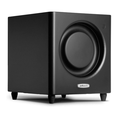
100 Watt Powered Subwoofer
Model #50-7660
MCM an inone company
650 Congress Park Drive
Centerville Ohio 45459
www.mcmelectronics.com

The MCM #50-7660 Active Subwoofer System is designed to be used with a wide variety of
today’s high fidelity and home theater systems. It is designed specifically for use with all formats of
multi channel home theater systems including Dolby Pro Logic, Dolby Digital, DTS, 5.1, 6.1 and 7.1
systems, and is also compatible with conventional two–channel stereo systems having no dedicated
subwoofer connection.
The subdued black ash finish is designed to match seamlessly with today’s home theater
components, and will complement any décor. It is designed to be a perfect aesthetic and acoustic
match for the MCM Model #50-9070/ 9075 and 50-9080/ 9085 Speaker Sets.
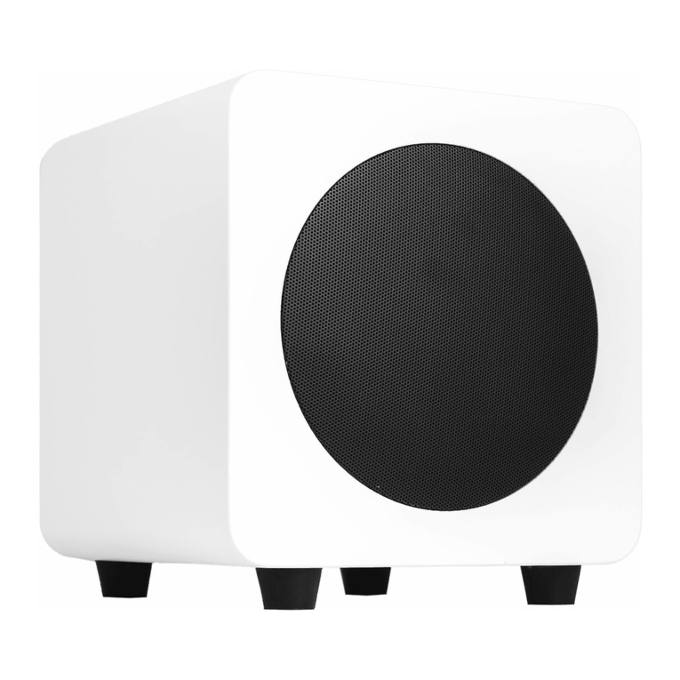
This unit features a long throw 10” woofer, mounted in a precisely tuned enclosure constructed from
medium density fiberboard, providing outstanding performance and appearance. The highly efficient
100W amplifier includes continuously variable gain and crossover frequency adjustments, allowing
compatibility with virtually any system, speaker arrangement and room setting. The internal active
subwoofer crossover, and tuned enclosure design combine to provide optimum response in the
critical frequency range below 150Hz.
Connection
The subwoofer includes both line level RCA, and speaker level inputs, allowing compatibility with
virtually any system.
Dolby 5.1/6.1/7.1 Receivers
Today’s 5.1 Dolby Pro Logic, Dolby Digital and DTS and similarly equipped receivers,
include an RCA type subwoofer output. In this case, simply connect a standard audio cable
from this output on the receiver, to the input connector labeled “LINE INPUT”. This is the
only connection required.
Conventional Two Channel Stereo Receivers
If the subwoofer is to be used with conventional older stereo receivers, which have no
specific subwoofer provisions, then it must be connected to the receiver’s speaker outputs.
To do this, connect the speaker output on the receiver, to the red and black push terminal
inputs on the subwoofer labeled “FROM AMPLIFIER”. Take care to ensure that correct
polarity (+ and -) connections are observed between the receiver and subwoofer. In the
event that the subwoofer is connected in this manner, the speakers then should be
connected to the subwoofer red and black push terminal outputs labeled “TO SPEAKERS”.
Again, taking care to ensure correct polarity.
Satellite Speaker Connection
Dolby 5.1 Receivers
Today’s 5.1, 6.1 and 7.1 Dolby Pro Logic, Dolby Digital and DTS and similarly equipped
receivers, are equipped with speaker outputs for front left and right, rear left and right, and
center channel speakers. All remaining speaker systems should be connected directly to
the receiver.
Conventional Two Channel Stereo Receivers
As stated above, the subwoofer should be connected the speaker outputs of the receiver,
and one pair of speakers will then be connected to the subwoofer. If the receiver is
equipped with A and B speaker outputs (two pairs), and a second pair is to be used, they
should be connected directly to the “B” speaker output.
Placement
For low frequency response, the subwoofer is best located in the front of the listening area,
on the same plane (or wall) as the front speakers, preferably in a room corner. As room
acoustics and personal preferences vary, some experimentation with placement may
produce more desirable results.


Power Switch
(On/Off/Auto): The amplifier may be manually turned on or off via this switch. In the Auto
position, the unit will default to “standby” mode. The power indicator will light
red. When an input signal is detected from the sound system, the unit will
automatically switch “on” and the power indicator will light green. After
approximately 20 minutes of silence, the subwoofer will automatically revert back
to “standby” mode.
Crossover
Frequency
Control:
Adjusts high frequency cutoff of the subwoofer from 50Hz to 200Hz. The optimum
position will depend upon the speaker systems used with this sub woofer,
placement and personal taste.
Phase
Selector: Due to common circumstances with subwoofer crossovers, often the subwoofer
ends up 180º out of phase with satellite speakers. When the subwoofer and
satellite speakers are out of phase, you will normally notice a decrease in mid-
bass response. Trial and error is the best method of determining the optimum
position for this selector.
Subwoofer
Level
Control:
Adjusts the output level of the subwoofer, relative to the output of the stereo or
home theater system.
Input / Output Connections
Line Input: Line level RCA input accepts signal from the subwoofer output on home heater
equipment.
High Level
Input: When no subwoofer or line level signal is available, this input may be connected
directly to the speaker output of the stereo system. Because this input is very
high impedance, it will add no noticeable additional load to speaker outputs.
High Level
Output: These are used for connection of satellite speakers. This output is functional only
when the High Level Inputs are utilized. A built–in 6dB crossover provides 125Hz
high pass output, ideal for typical smaller satellite speaker systems.
Technical
Questions: If assistance is required with the application of this subwoofer amplifier, including
calculating combined impedance of multiple drivers, contact MCM Electronics
Technical Support at 1-800-824-TECH (8324), or email: tech@mcmelectronics.com
Specifications
Power Output: 100W minimum RMS
THD: 0.1% THD @ 100W RMS
1% THD @ 120W RMS
10% THD @ 140W RMS
Power Requirement: 110VAC,60Hz, 180W
Overall Dimensions: 14" (H) x 13.75" (W) x 14.5" (D)


Subwoofer hum and “ground loops”
Typical home theater systems often include several devices which are separately grounded through
the residential wiring system. Since subwoofers are often located some distance away from other
home theater components, they tend to be grounded through a different wiring path. Because of
this, a minute amount of voltage potential may exist between these different paths. The additional
ground path created by the cable TV or satellite dish coaxial cable often worsens this problem.
When the components are connected together, via the audio cable, a ground loop is formed. This
ground loop will manifest itself in one of two ways:
•60 cycle hum from subwoofer, home theater speakers or television speakers
•Bars, which appear on the video, screen, usually starting from the lower portion of the
screen, slowly moving upward
If either of these conditions exist, there is a strong likelihood of the presence of a ground loop. To
test this problem, try the following:
•Disconnect the coaxial cable from the cable television source, or satellite dish
It this eliminates the hum, or hum bars, the ground loop exists at this point. This loop may
be eliminated by the insertion of a Ground Loop Isolator, such as MCM #33-8700. This
device is a simple in-line adaptor that may be inserted at any location between the cable
wall connector and the television or satellite receiver.
•Disconnect the audio cable from the input to the subwoofer
If this eliminates the hum, or hum bars, the ground loop exists at this point. This loop may
be eliminated by the insertion of a Ground Loop Isolator, such as MCM #555-2707. This
device is a simple RCA connection device which may be inserted at any location between
two audio components.
Warranty Information
This MCM Custom Audio active subwoofer is warranted for a period of one year. This warranty is
limited to manufacturer defects, either in materials or workmanship. MCM is not responsible for any
consequential on inconsequential damage to any other unit or component or the cost for installation
or extraction of any component of the audio system.
In case of a product failure, please contact our Customer Service Department at 877-672-3532 to
obtain a Return Authorization #.
Warranty Limitations
There are no other warranties, either express or implied, which extend the foregoing, and there are
no warranties of merchantability or fitness for any particular purpose. The warranty will not cover
incidental or consequential damage due to defective or improper use of products.
MCM Electronics
650 Congress Park Drive
Centerville Ohio 45459
www.mcmelectronics.com
This manual suits for next models
1
Table of contents
