MEDIUM 22483 User manual
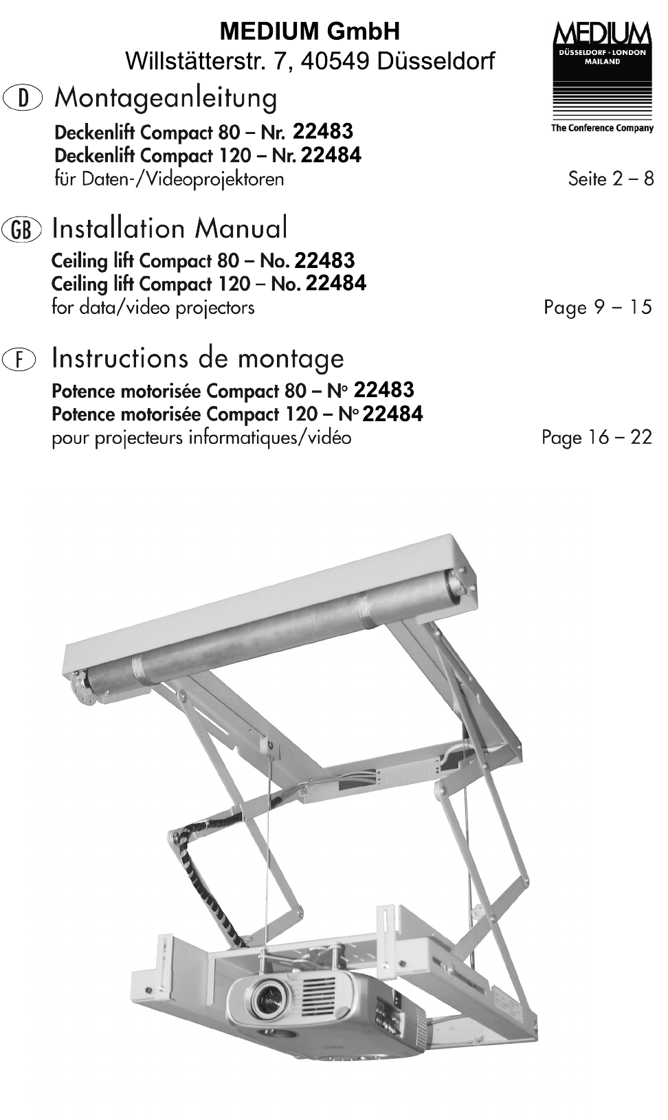
MEDIUM GmbH
Willstätterstr. 7, 40549 Düsseldorf
22483
22483
22483
22484
22484
22484
Funktions-Beschreibung
Ultraflacher Deckenlift für alle gängigen Daten-/Videoprojektoren,
geräuscharme Laufbewegung mit Scherengelenkmechanismus,
Projektor-Netzzuleitung vorinstalliert, Spiralschlauch für sichere
Kabelführung der Datenleitungen.
Der Antrieb erfolgt über einem Einphasen-Kondensatormotor
(230V/50 Hz) über ein 3-stufiges, wartungsfreies Planetengetrie-
be und verfügt über eine elektronische Abschaltung.
Eine elektromechanische Scheibenbremse sorgt für genaues An-
halten. Die volle Bremskraft wird beim Ausschalten oder Strom-
ausfall sofort erreicht.
Die Einstellung der beiden End-Positionen erfolgt einfach durch
eine Programmier-Einheit. (Zubehör Best.-Nr. 7466-100/-101)
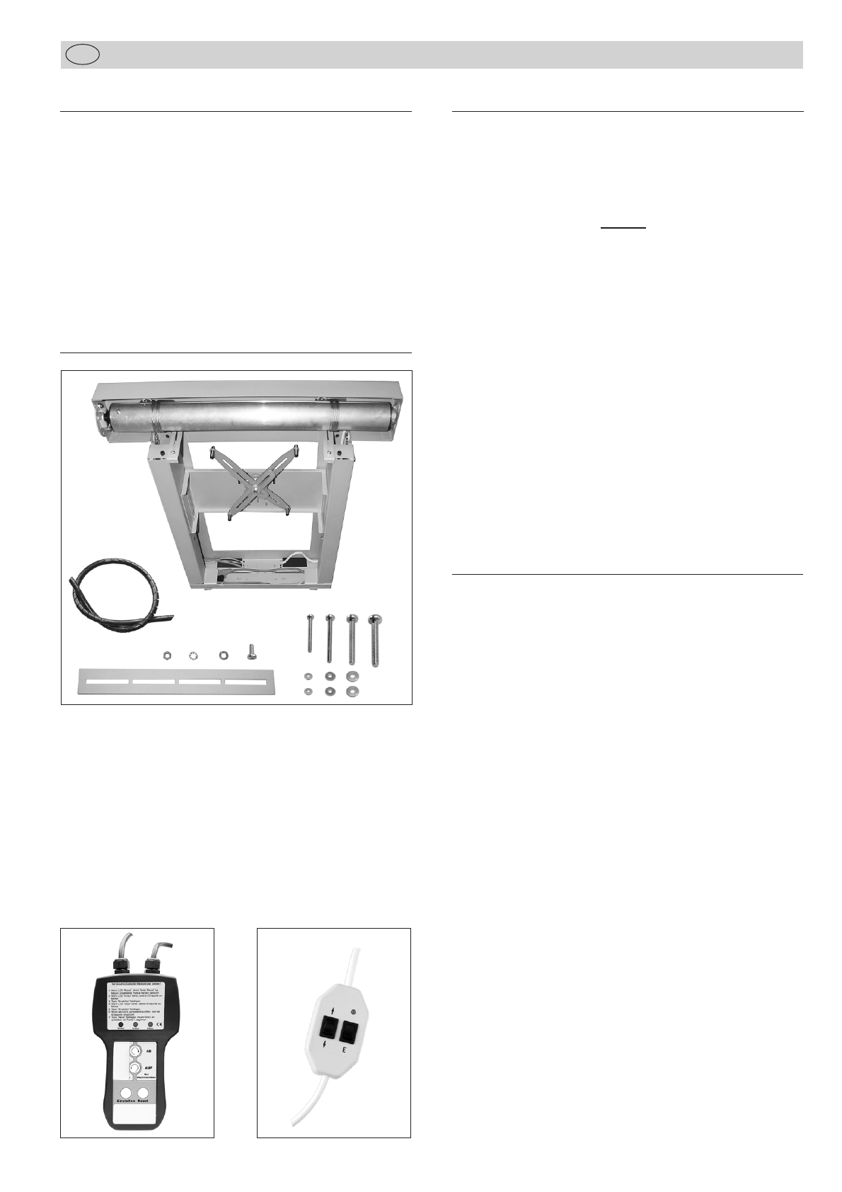
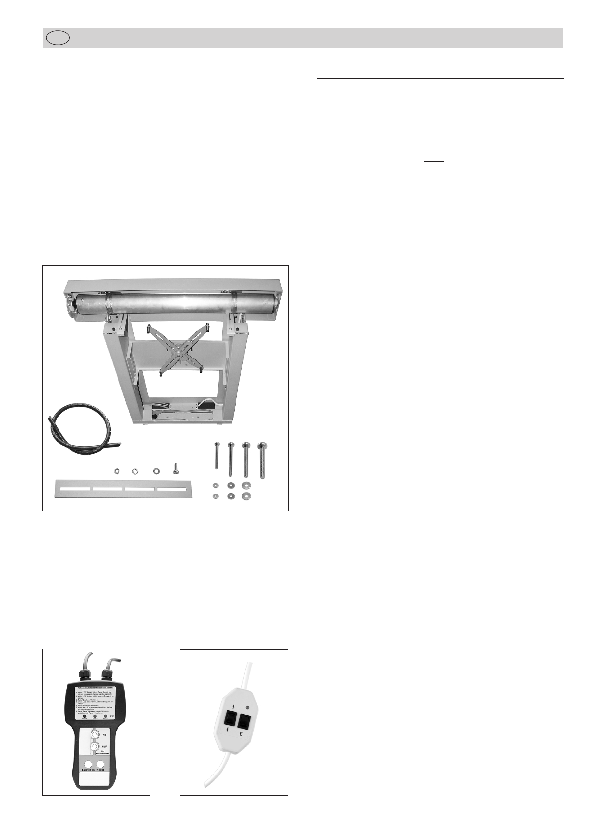
Lieferumfang
Der Deckenlift wird zum sicheren Transport im eingefahrenem
Zustand geliefert und kann sofort montiert werden.
Ein Spiralschlauch zum Fixieren Ihrer Datenübertragungskabel,
sowie vier Verlängerungsschienen für Liftbodenblech und vier
Schraubensätze zur Projektorbefestigung gehören zum Lieferum-
fang!
Eine Bohrschablone 1:1 ist beigelegt.
Befestigungsmaterial für Ihre Deckenkonstruktion gehört nicht zum
Lieferumfang!
Technische Daten
Farbe: Lift pulverbeschichtet silbergrau
metallic (RAL 9006)
Einbauhöhe:Compact 80:
min. 120 + X mm bei einer
Projektor-
höhe < 65 mm
(X = Projektorhöhe – 65 mm)
Beispiel:
Projektorhöhe 100 mm =
155 mm Einbauhöhe
Compact 120:
min. 140 + X mm bei einer
Projektor-
höhe < 85 mm
Projektorbefestigung: Universelle Projektor-Halterung
ausfahrbarer Hub:Compact 80: bis 80 cm
Compact 120: bis 120 cm
Gewicht des Lifts:Compact 80: 24 kg
Compact 120: 26 kg
max. Projektorgröße: 50 x 35 cm
max. Projektorgewicht: 20 kg
Stromversorgung: 230 V, 50 Hz
Platzbedarf an Rohdecke: 68 x 70 cm
Deckenausschnitt: 60 x 50 cm
Deckenabschluss: optional
Nr. 7466-10 bzw. Nr.7466-11
Optionales Zubehör
Nr. 7466-10 Deckenabschlussplatte mit T-Profilrahmen
für verdeckten Einbau, Integration des Decken-
ausschnittes (500 x 600 mm) in Deckenlift.
Farbe: pulver beschichtet matt - weiß (RAL 9003)
Nr. 7466-11 Deckenabschlussplatte (550 x 650 mm)
Standard
zur Abdeckung des Deckenausschnittes
(500 x 600 mm).
Farbe: pulverbeschichtet matt - weiß (RAL 9003)
Nr. 7466-100 Programmiereinheit Standard
mit 4-adriger Anschluss-Leitung zum Einstellen
der Endpositionen
Nr. 7466-101 Programmiereinheit Elektronik
mit 4-adriger Anschluss-Leitung zum Einstellen
der Endpositionen (Komfortausführung),
wiederverwendbar
Nr. 7466-15 Sicherheitsschalter
Mechanischer Schalter 230 VAC, 10 A, für
Stromabschaltung des Projektors bei einge-
fahrenem Deckenlift, Endstellung einstellbar
bzw. Statussensor (Deckenlift eingefahren für
Mediensteuerung)
Nr. 7466-20 Metallverkleidung
für Sichtanbringung unter der Decke, 4-teilig,
Höhe ca. 35 cm, Farbe weiß (RAL 9003)
Nr. 5944 Funk-Fernbedienung
mit drahtlosem Schalter und Handsender,
Reichweite bis zu 30 m
Nr. 5699-13 IR-Fernbedienung
1-Kanal, inkl. Wandtaster und Handsender
Nr. 5944-1 Schlüsselschalter
Nr. 5944-2 Drehschalter/-taster
10A/250 VAC, 2-polig, Aufputz, alpinweiß,
für Auf-/Ab-Steuerung
Programmiereinheit
Standard
Programmiereinheit
Elektronik
2
Montageanleitung
D
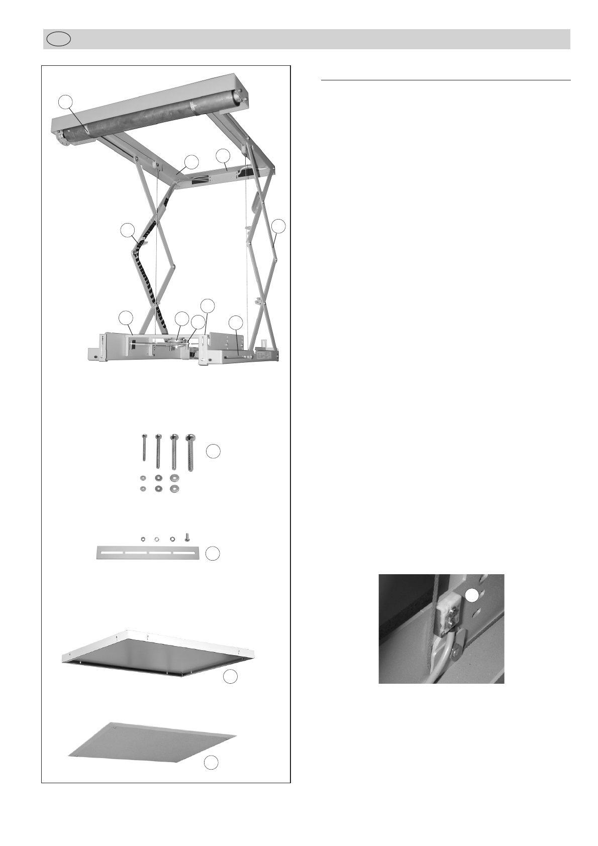
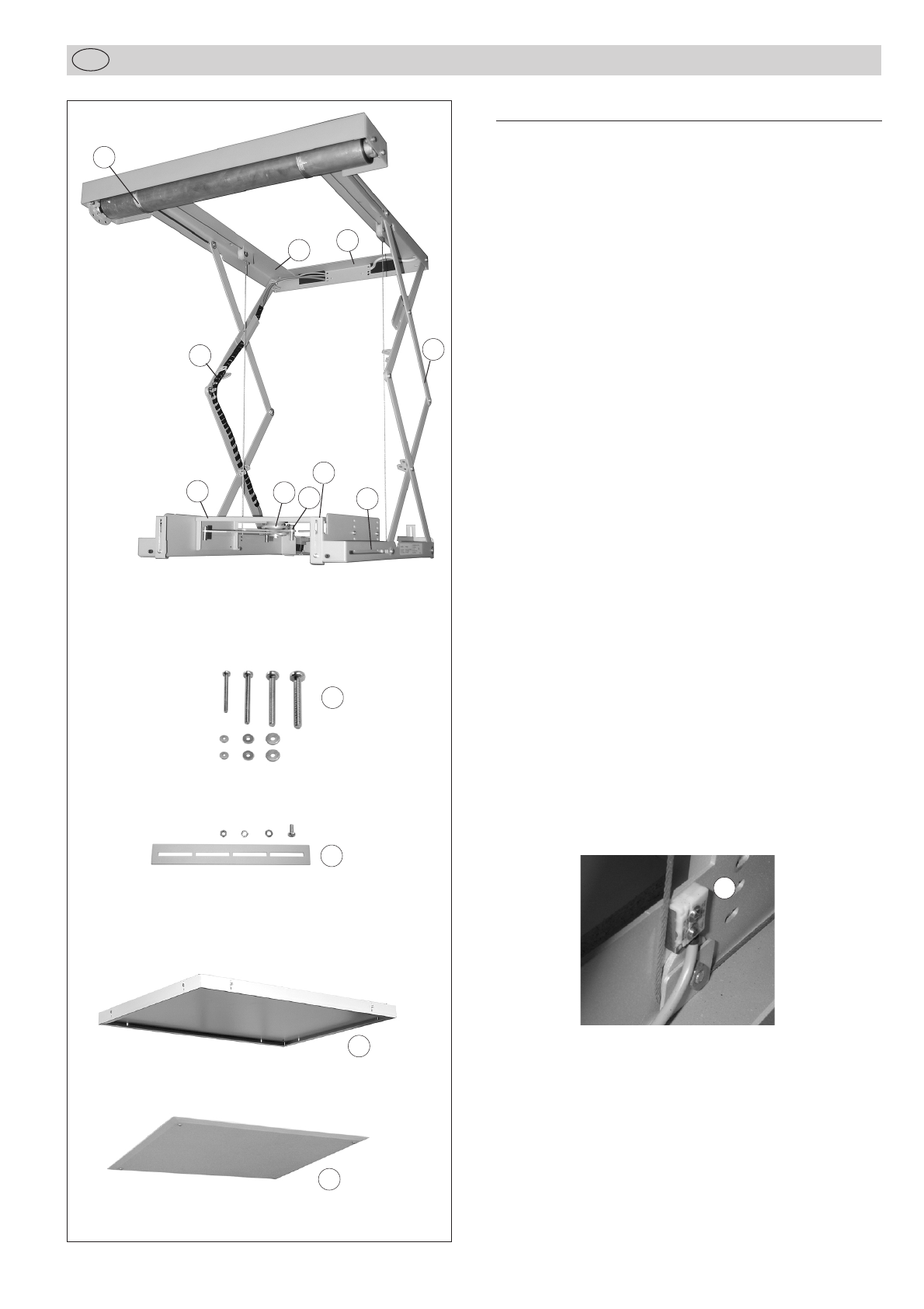
Zeichenerklärung
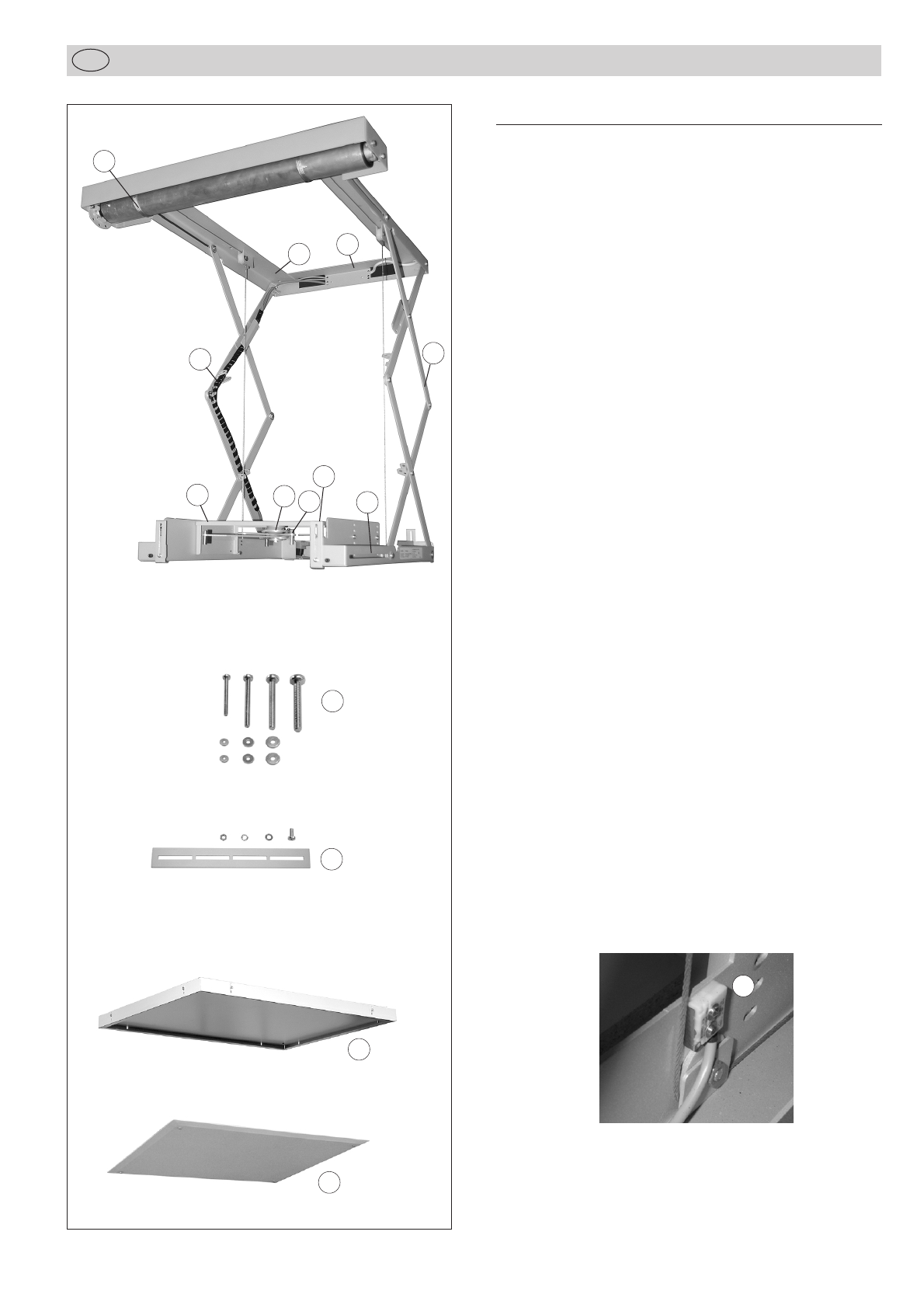
1Befestigungsrahmen mit Montagebohrungen
(siehe Maßskizze)
2Motor mit Seilzug
3Anschlussdose für Elektroanschluss
4Zwei Sicherheitsschalter für Seilspannung
5Kabelführung mit Netzkabel und Kabel zu den beiden
Sicherheitsschaltern
6 Compact 80: 2 Scherenpaare für jeweils 40 cm Hub
Compact 120: 3 Scherenpaare für jeweils 40 cm Hub
7Variabel einstellbare Montagebrücke
8Projektorhalterung mit Justagemöglichkeiten
9Projektorspinne mit vier beweglichen Armen mit
Gewindeabstandsbolzen
10 Vier Schraubensätze M3/M4/M5/M6 mit U-Scheiben
11 Vier Verlängerungsschienen mit Schrauben und Muttern zur
erweiterten Höheneinstellung der Deckenabschlussplatte
12 Optionale Deckenabschlussplatte
mit T-Profilrahmen für verdeckten Einbau.
Farbe: pulverbeschichtet matt-weiß (RAL 9003)
Best.-Nr. 7466-10
13 Optionale Deckenabschlussplatte Standard
zur Abdeckung des Deckenausschnittes
Farbe: pulverbeschichtet matt-weiß (RAL 9003)
Best.-Nr. 7466-11
Hinweis:
Bitte überprüfen Sie, vor der Montage bzw. nach Auffahren des
Lifts auf ein Hindernis, die beiden Sicherheitsschalter (4) –das
Zugseil muss die Feder an den Sicherheitsschalter drücken (siehe
Abb.)!
13
2
5
10
11
4
6
4
7
89
4 x}
12
13
4 x}
4 x}
4
←
3
Montageanleitung
D

Sicherheitshinweise
Der Deckenlift darf nur von autorisierten und geschulten Fach-
kräften montiert oder repariert werden.
Sie sollten unbedingt diese Montage-/Betriebsanleitung
des Gerätes lesen, sowie die Sicherheitshinweise genau beach-
ten!
Für den Betrieb des Gerätes gelten in jedem Falle die örtlichen
Sicherheits- und Unfallverhütungsvorschriften und die länder-
spezifischen Bestimmungen für Schulungs- und Konferenz-
räume.
Bei Ausfahren des Liftes ist der Gefahrenbereich abzusichern.
Die Deckenkonstruktion muss mind. das 10-fache des max.
Gewichts von Lift und Projektor tragen können.
Bei sämtlichen Arbeiten am Deckenlift ist darauf zu achten,
dass keine losen Teile (z.B. Werkzeuge) im Lift zurückgelassen
werden, die herabstürzen können.
Hände und andere Objekte nicht in bewegte Teile (z.B.
Scherengitter) bringen. Es können ernsthafte Verletzungen
(Quetschungen) auftreten.
Es dürfen keine brennbaren Stoffe in der Nähe des eingefah-
renen Deckenliftes vorhanden sein.
Der Lift ist ca. 26 kg schwer. Sehen Sie entsprechende Sicher-
heitsvorkehrungen und Arbeitshilfen vor (z.B. Arbeitsbühne,
Flaschenzug, Absturzsicherung).
Der Stromanschluss an eine 230 V-Anlage darf nur von einer
Elektro-Fachkraft (lt. VDE 0100) vorgenommen werden.
Die Anlage muss an das Stromnetz durch eine Schaltvorrichtung
mit allpoliger Trennung und Kontaktöffnung von mind. 3 mm
angeschlossen sein, um die Anlage spannungsfrei zu schalten
(lt. VDE 0700).
Vor allen Wartungsarbeiten zuerst Anlage vom Netz trennen.
Hauptschalter im Raum, bzw. in Sichtweite zum Gerät
installieren, um beaufsichtigtes Ein- bzw. Ausfahren des
Liftes sicherzustellen.
Die Mindesthöhe in ausgefahrener Endlage soll 2,5 m nicht
unterschreiten.
Schäden durch Gewaltanwendung, falsche Handhabung,
falsche Verkabelung sowie dadurch entstandene Folgeschäden
fallen nicht unter die Garantieleistung.
Achtung:
Das Seil wickelt sich im Normalbetrieb konstruktionsbedingt
immer einlagig auf der Seiltrommel auf.
Bitte kontrollieren Sie vor der ersten Inbetriebnahme, dass
das Seil in jedem Fall einlagig, ohne Überkreuzungen auf-
gewickelt ist.
Im Falle einer Überkreuzung fahren Sie den Lift ganz heraus
und vorsichtig wieder ein.
Eine Sicherheitsschaltung stoppt den Lift bei Auffahren auf
ein Hindernis in Abwärtsrichtung.
Vorbereitungen der Decke
Der Deckenlift sollte an einer tragfähigen Deckenkonstruktion
befestigt werden. Bitte besorgen Sie sich das entsprechende
Befestigungsmaterial, ausgelegt für eine Last bis 200 kg, im Fach-
handel. Gewinde-Durchmesser sollten M8 sein.
Die Deckenkonstruktion muss mindestens das 10-fache des maxi-
malen Gewichtes von Lift und Projektor (4 x 50 kg) tragen kön-
nen.
Montage des Liftes in abgehängte Decke
Der Lift benötigt einen Deckenausschnitt von mindestens 60 x 50
cm. Die niedrigste Einbauhöhe des Lifts beträgt 120 mm, voraus-
gesetzt die Höhe des eingesetzten Projektors liegt nicht über 65
mm.
Hinweise:
Entfernen Sie um den Einbauplatz ausreichend die Zwischendecke,
damit Sie für die Installation genügend Platz schaffen.
Gehen Sie bei der Bestimmung des Montage-Standorts des Lifts
davon aus, dass die Vorderkante des Lifts im mittleren Bereich
der Zoom-Möglichkeit Ihres Projektors zur Leinwandgröße liegt
und das Objektiv auf die Mittelachse der Leinwand ausgerichtet
ist. Die Feinjustage-Möglichkeiten des Projektors liegen nach der
Montage nur in der horizontalen und vertikalen Ebene (siehe
Seite 8).
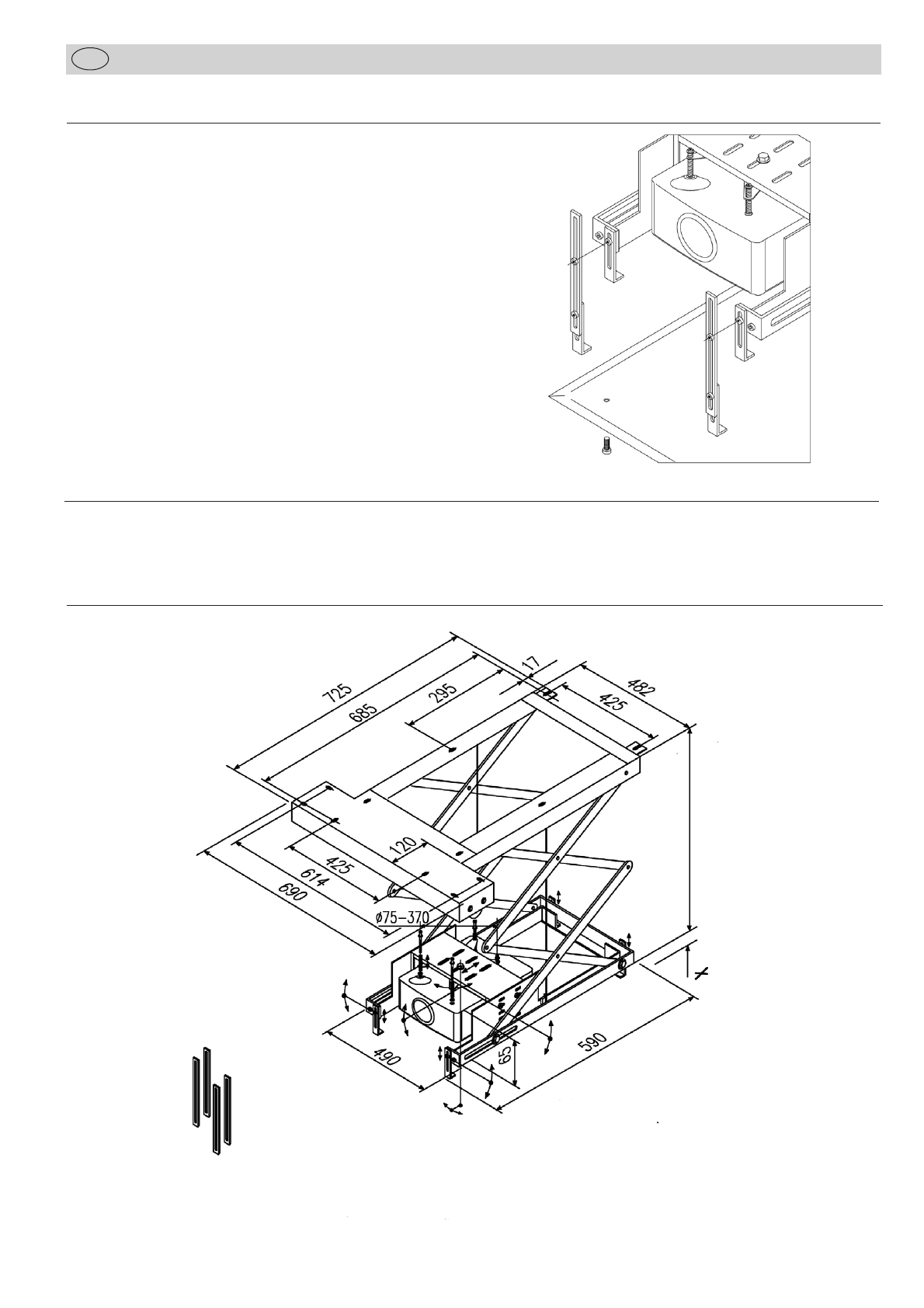
Montieren Sie den Deckenlift im eingefahrenen Zustand über die
zugänglichen äußeren vier Montagepunkte an die tragfähige
Decke. Legen Sie die Bohrlöcher mit Hilfe der Schablone fest
(siehe Zeichnung).
Die beiden inneren Montagepunkte (5 + 6) müssen unbedingt nach
dem ersten Ausfahren des Lifts verschraubt werden!
Bohrschablone
Hinweis:
Wenn Sie eine Deckenabschlussplatte mit T-Profilrahmen (Best.-
Nr. 7466-10) für die Einlage des Zwischendeckenausschnitts an-
bringen wollen, müssen Sie für die vier Halteschrauben der
Deckenabschlussplatte Öffnungen in der Einlage schaffen, damit
bei einem Defekt die Deckenabschlussplatte abgenommen wer-
den kann.
4
3
51
2
6
4
Montageanleitung
D

Stromversorgung
Der Elektroantrieb besteht aus einem reversierbaren Einphasen-
Wechselstromkondensator-Motor mit eingebauter elektronischer
Endabschaltung, Bremse und Getriebe.
Die Steuerung des Lifts kann erfolgen über:
1. Funk-Fernbedienung Best.-Nr. 5944-0
2. IR-Fernbedienung Best.-Nr. 5699-13
3. Schlüsselschalter Best.-Nr. 5944-1
4. Drehschalter-/Taster Best.-Nr. 5944-2
5. Relaiskontakt über Mediensteuerung
(z.B. Kindermann, AMX, etc.)
Der Elektroanschluss des Lifts erfolgt bauseitig an der An-
schlussdose. Die Spannungsversorgung des Projektors erfolgt
über eine bauseits zu installierende abschaltbare Steckdose.
Alle Zuleitungen zum Lift werden durch die entsprechende
Öffnung am oberen Metallrahmen vorgenommen. Das Netzkabel
für den Projektor und die Kabel für die Sicherheitsschalter sind
bereits an den rechten Scherenpaaren vormontiert. Verwenden
sie die vorhandenen Kabelhalterungen an den linken Scheren-
paaren zur Verlegung der Signal- und Steuerkabel des Projektors.
Setzen Sie den mitgelieferten Spiralschlauch und die Kabelbinder
ein, befestigen Sie die Signal- und Steuerkabel, analog der be-
reits werkseits vormontierten Kabel. Ein Quetschen oder Erfassen
der Zuleitungen durch die beweglichen Scheren ist somit auszu-
schließen.
Schaltplan Installation Schalter/Taster
Montageanleitung
D
5
Schaltplan Programmiereinheit
Netz
Deckenlift
Projektor
Schalter für Projektor
Schalter zur
Seilspannungsüberwachung
Netz
Anschlussdose
Deckenlift Programmier-
einheit
7466-100 oder
7466-101
blau
schwarz
braun
grün/gelb
blau schwarz
braun
grün/gelb
PE N L
grün/gelb grün/gelb

Stromlaufplan Programmiereinheit
Montageanleitung
D
Endlage 1 Lift ist komplett eingefahren
Endlage 2 Lift ist komplett ausgefahren
Zur Programmierung neuer Einstellungen stehen Ihnen die Pro-
grammiereinheiten Standard (Nr. 7466-100) und Elektronik
(Nr. 7466-101) aus dem Zubehörprogramm zur Verfügung.
a) Programmiereinheit Standard
Installieren Sie die Einheit entsprechend des nebenstehenden Strom-
laufplans. Beachten Sie die farbliche Übereinstimmung der
Installationsleitungen mit der Motorleitung. Stellen sie die Strom-
verbindung erst nach der Installation her!
Einstellung der Endpunkte:
1. Mindestens 6 Sek. Taste E (2) bestätigen. Der Antrieb springt
in den Einstellmodus. Kurzes Anhalten nach Anlauf signali-
siert den Einstellmodus!
2. Untere Endposition (Projektionsstellung) durch Betätigen der
Taste (1) anfahren.
3. Mindestens 3 Sek. Taste E (2) betätigen. Die untere Endposition
(Projektionsstellung) ist gespeichert.
4. Obere Endposition vorsichtig durch Betätigen der Taste (1)
anfahren (Ruhestellung, der Lift ist eingefahren).
5. Mindestens 3 Sek. Taste E (2) betätigen. Die obere Endposition
(Ruhestellung) ist gespeichert.
6. Nach der Einstellung sollte ein Probelauf vorgenommen wer-
den. Hält der Deckenlift an den eingestellten Endpositionen,
so ist die Einstellung erfolgreich durchgeführt worden. 6
Hinweis: Achten Sie bei der Leitungsverlegung Schalter/Taster
(Auf/Ab) zum Lift darauf, dass an der Verbindungsstelle die
Motorsteuerleitungen nicht vertauscht werden! (Braun= Auf,
Schwarz= Ab)
Stromlaufplan InstallationSchalter/Taster
Sicherheitsschalter
grün/gelb
blau
braun
schwarz
schwarz
blau
grün/gelb
Abzweigdose
bauseits blau
Netz
Normalbetrieb
Programmiereinheit
Standard 7466-100
Netz
Programmierbetrieb
Anschlussklemme
von Prog.-Einheit
7466-100
oder 7466-101
Schalterdose
für Taster/Schalter
bauseits
Betriebsanzeige
2
1
Motor
gr/ge
bl
sw
br
Kabel zwischen
Abzweig- und
Schalterdose
mind. 6-adrig
(z.B. NYM 7x1,5mm2)
br
bl
gn/ge
sw
Einstellung der Endlage des Lifts
b) Programmiereinheit Elektronik
Installieren Sie die Einheit wie im Stromlaufplan gezeichnet, zur
Einstellung der Endpunkte folgen Sie der Bedienungsanleitung auf
der Einheit.
Nach erfolgreichem Probelauf trennen Sie die Programmiereinheit
vom Stromnetz und lösen die Verbindung.
Anschlussdose
am Lift
Sicherheitsschalter
grün/gelb
blau
braun
schwarz
blau
grün/gelb
Abzweigdose
bauseits blau
Netz
schwarz br
bl
sw
Kabel zwischen
Abzweig- und
Schalterdose
mind. 6-adrig
(z.B. NYM 7x1,5mm2)
Motor
Anschlussdose
am Lift
gn/ge
Wandschalter/-taster
z.B. 5944-2
Schalterdose
für Taster/Schalter
bauseits

7
Sicherheitshinweise zur Endlagen-Einstellung
1. Taster/Schalter und Steuerungen dürfen keinen gleichzeitigen
Auf- und Ab-Befehl ermöglichen, dies würde zu einem Defekt
der Anlage führen. Bitte verwenden Sie nur mechanisch oder
elektrisch verriegelte Schalter/Taster!
2. Die Umschaltzeit beim Wechsel der Richtung muss größer 0.5
Sek. betragen.
3. Bei Probeläufen und im Betrieb muss vermieden werden, dass
der Antrieb überhitzt wird, d.h. die Einschaltdauer von 4 min.
nicht überschreiten! Eine Überhitzung kann zum Ansprechen
des eingebauten Thermoschutzes führen. In diesem Falle bitte
mind. 10 Minuten warten, bis der Antrieb wieder betriebs-
bereit ist.
4. Prüfen Sie, ob beide Zugseile, gleiche Länge haben, sowie
straff und gleichmäßig auf der Welle des Antriebmotores lau-
fen.
5. Es ist darauf zu achten, dass im späteren Betrieb der Projektor
nur im ausgeschalteten und abgekühlten Zustand eingefahren
wird. Das heißt: nach dem STANDBY-Schalten des Projektors
mit Verlöschen der Projektorlampe, muss mind. 5 Minuten
gewartet werden, bis der Lift eingefahren werden darf.
Wird die Steuerung automatisch von einer Mediensteuerung
übernommen, ist die Programmierung der Mediensteuerung
entsprechend durchzuführen.
Montage des Projektors
Voraussetzung des Projektors:
Drei oder vier Gewindebuchsen (M3, M4, M5 oder M6 ) an der
Unterseite mit einem Befestigungsbereich zwischen 75 und 370mm.
max. Gewicht: 20 kg, max Gehäusemaße: 50 x 35 cm
Eine Befestigung mit nur 3 Tragearmen ist möglich.
4 x Schraubensatz mit entsprechenden Beilagscheiben M3, M4,
M5, M6 sind beigepackt.
Justagemöglichkeit des Projektors
1. Der unter der Montagebrücke hängende Projektor kann durch
leichten Kraftaufwand gedreht sowie um ca. ±20°geneigt
werden.
Stimmt die Ausrichtung des Projektors zur Leinwand, kann die
Schraube auf den Projektorhalter (8) mit einem Gabel-
schlüssel angezogen werden.
2. Der Projektorhalter sitzt im Zentrum der Montagebrücke (7)
und kann bei Bedarf nach links und rechts, sowie nach hinten
versetzt werden (s. Abb.).
Dazu die Verschraubung des Projektorhalters lösen.
Achten Sie beim Versetzen darauf, dass die Schrauben der
Projektorspinne von oben erreichbar bleiben.
3. Die Montagebrücke (7) kann nach Lösen der vier Schrauben
links und rechts abgenommen und bei Bedarf gedreht wer-
den, wenn es die Höhe der Zwischendecke zulässt bzw. der
Projektor nicht in die Montagebrücke passt Abb.4.
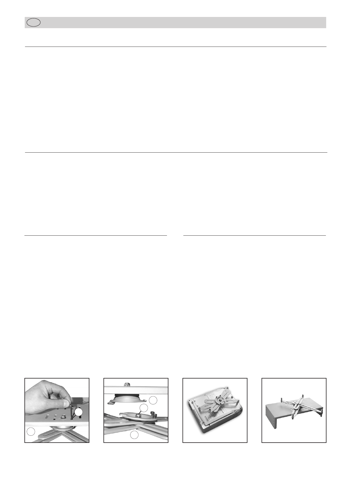
Projektor einsetzen
Die Projektorspinne (9) mit vier Tragearmen und Gewindeabstands-
bolzen ist am Projektorhalter (8) eingehängt und kann nach Lok-
kern der beiden Schrauben (a) Abb.1 durch die Schlitze der
Montagebrücke (7) seitlich abgenommen und auch wieder einge-
hängt werden Abb.2.
Mit den Gewindeabstandsbolzen können Sie unterschiedliche
Höhenlagen der Gewindebuchsen Ihres Projektors ausgleichen.
Lockern Sie mit 2 Gabelschlüsseln 10 mm die Verschraubung (b)
der Projektorspinne Abb.2.
Legen Sie Ihren Projektor mit der Unterseite nach oben auf eine
weiche Unterlage Abb.3.
Stellen Sie fest, welcher der Schraubensätze (10) zu den Gewinde-
buchsen Ihres Projektors passt und befestigen damit die Projektor-
spinne durch die vier Abstandsbolzen. Setzen Sie dazu beidseitig
die passenden U-Scheiben ein.
Ziehen Sie die Verschraubung (b) der Projektorspinne an.
Hängen Sie die fertig montierte Einheit in den Projektorhalter (8)
der Montagebrücke (7). Sichern Sie die Verbindung durch Fixie-
rung der beiden Schrauben durch die Schlitze der Montagebrücke.
Als Werkzeuge zur Projektormontage benötigen Sie:
1 x Schraubendreher + Inbus Nr. 3
2 x Gabelschlüssel 10 mm
Abb. 1 Abb. 2 Abb. 3 Abb. 4
7
8
9
ab
Montageanleitung
D
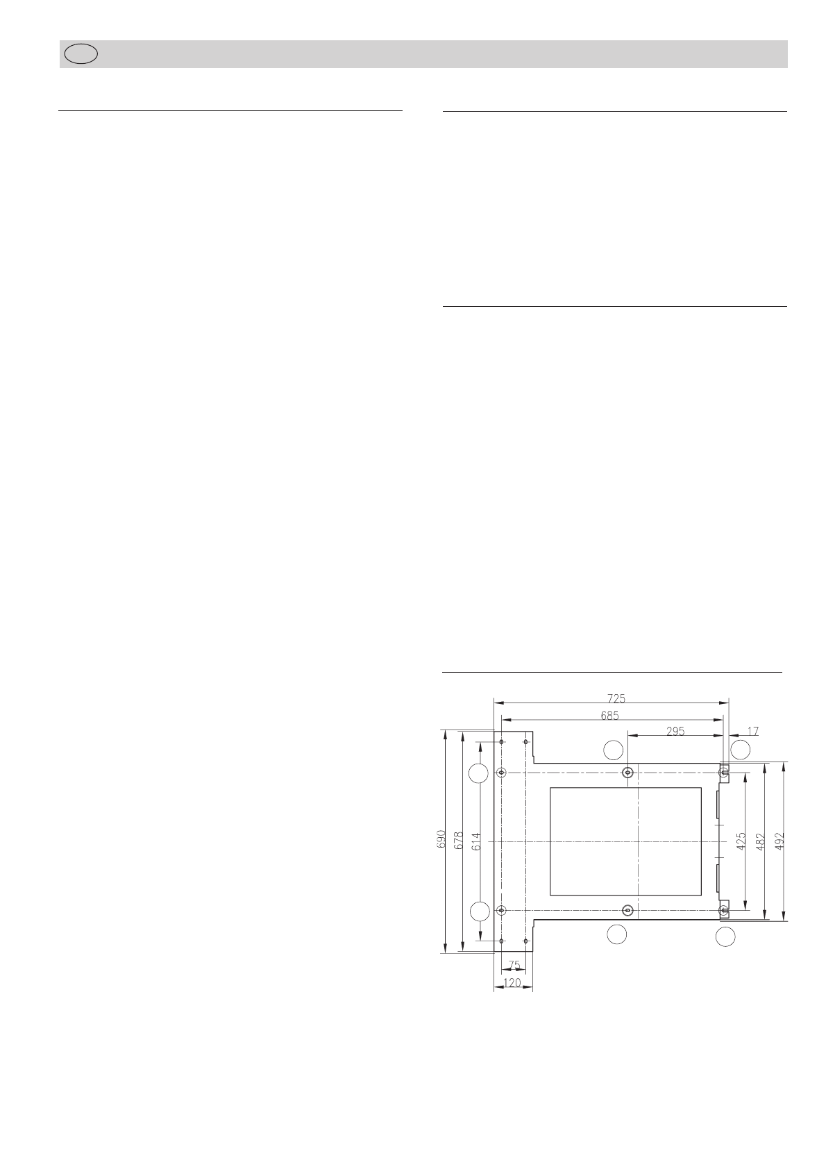
Die Deckenabschlußplatte (13) wird über vier verstellbare Winkel-
schienen an den Lift geschraubt. Nach Lockern der Winkelschienen
kann diese Abschlußplatte in der Höhe verstellt werden. Wenn die
Höhe nicht erreicht werden kann, können vier Verlängerungs-
schienen (11) eingesetzt werden (Abb.).
Wartung und Pflege
Der Deckenlift ist grundsätzlich wartungsfrei. Einmal jährlich sollte er auf Sicherheit und Zuverlässigkeit untersucht werden, das sind:
Kabelführung, Stahlseile, Motor auf Ölspuren, Kabelverbindungen und Befestigung.
8
Montageanleitung
D
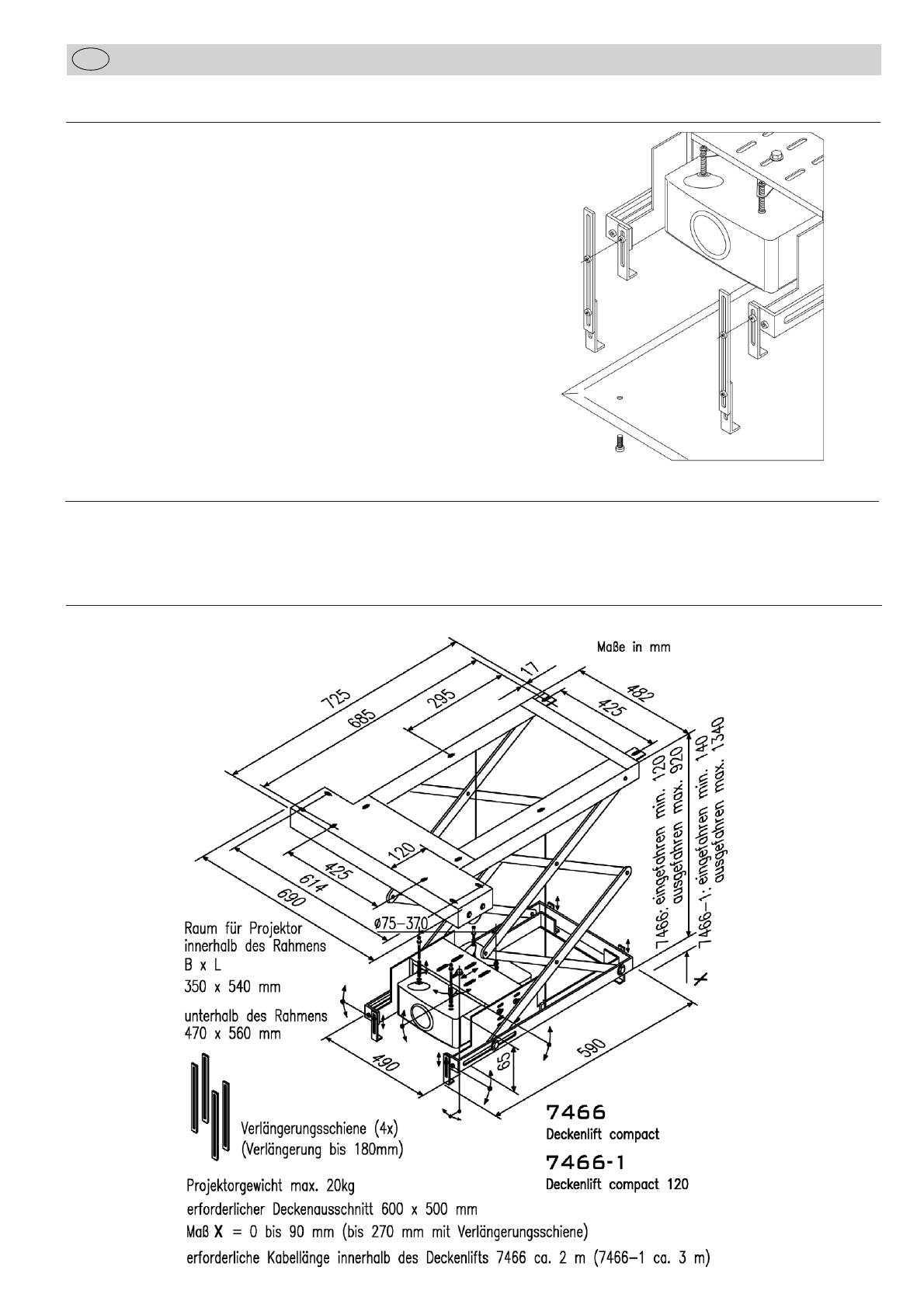
Einstellung der optionalen Deckenabschlußplatte Standard
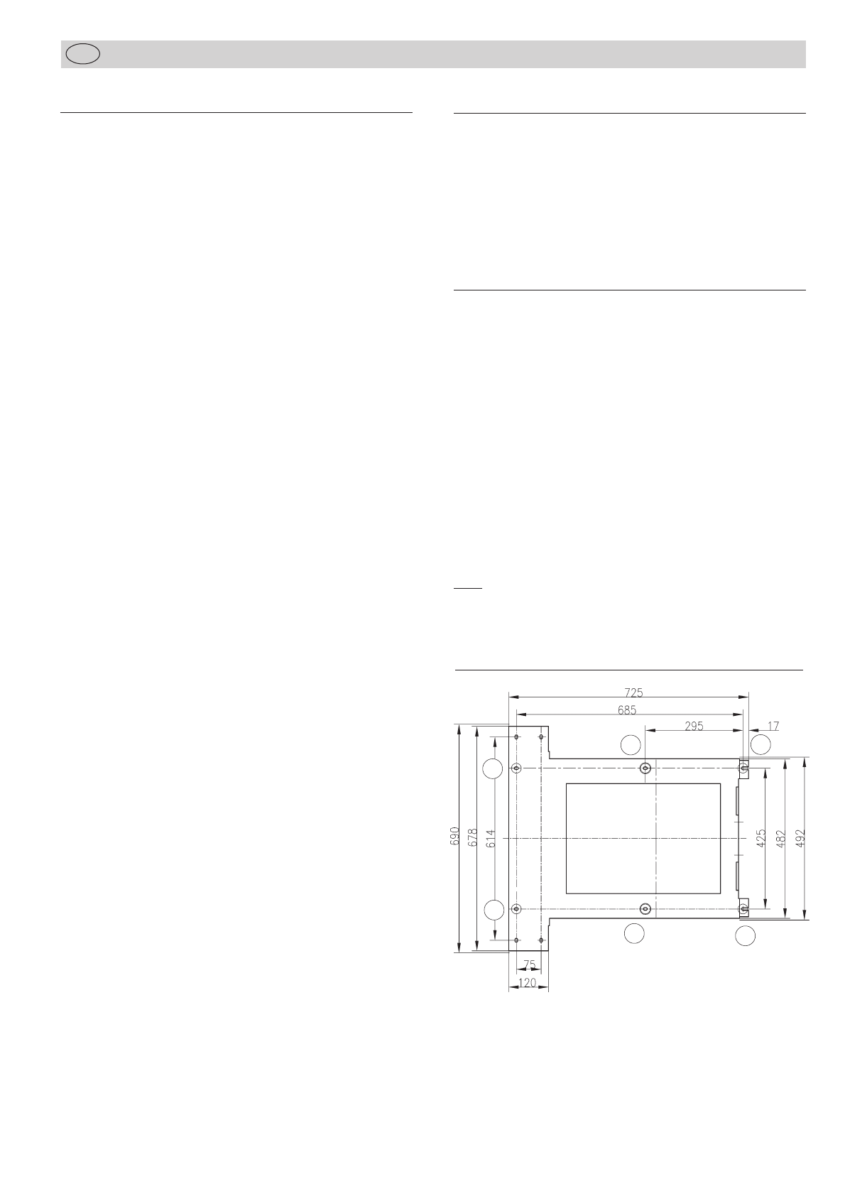
Maßskizze
Function
Extremely flat ceiling lift for all customary data/video projectors.
Low noise movements with concertina mechanism, pre-installed
power supply, spiral cable guide for safe power and data supply.
The lift is powered by a single-phase condenser motor via a
3-gear maintenance-free planetary transmission and features an
electronic safety switch.
An electro-mechanical disc break allows exact stops. In case of a
power blackout or when switching theunit off the full breaking
power is available immediately.
Adjusting the two stop positions can be simply done with the help
of a programming unit (optional accessory No. 7466-100 or
7466-101).
Delivery
For safe transport the ceiling lift is delivered in lifted condition. It
can be mounted immediately.
Supplied with flexible spiral for guiding the cables, and with four
extension arms for bottom tray, and four sets of screws for fastening
the projector!
A stencil for drill-holes (1:1) is included.
Fixing material for your ceiling construction is not supplied!
Technical data
Colour: Lift coated silver grey metallic
(RAL 9006)
Installation measurements:Compact 80:
min. 120 + X mm if projector height
is < 65 mm
(X = projector height –65 mm)
e.g. : projector height 100 mm =
155 mm installation height)
Compact 120:
min. 140 + X mm if projector height
is < 85 mm
Projector mounting: universal projector mount
Lifting range:Compact 80: up to 80 cm
Compact 120: up to 120 cm
Weight of the lift:Compact 80: 24 kg
Compact 120: 26 kg
Max. projector size: 50 x 35 cm
Max. projector weight: 20 kg
Power supply: 230 V 50 Hz
Min. size of ceiling: 68 x 70 cm
Cutout of ceiling: 60 x 50 cm
Ceiling plate: optional
No. 7466-10 resp. No. 7466-11
Optional accessories
No. 7466-10 Ceiling plate with T profile
for invisible mounting, integration of the ceiling
cutout (500x600 mm) in the lift
colour: matt white (RAL 9003)
No. 7466-11 Ceiling plate (550x650 mm) standard version
for covering the ceiling cutout (500x600 mm),
colour: coated matt white (RAL 9003)
No. 7466-100 Programming unit standard
with 4-pin connection cable, for programming
the stop positions
No. 7466-101 Electronic programming unit
for more convenience, with 4-pin connection
cable, for programming the stop positions,
reusable
No. 7466-15 Safety switch
Mechanical switch 230VAC, 10A, for cutting
off the projector from power when ceiling lift
is lifted, stop position adjustable.
No. 7466-20 Metal panelling
for visible mounting on the ceiling, 4 parts,
height 35 cm, white colour (RAL 9003)
No. 5944 Radio remote control
with wireless switch and mobile sender,
up to 30 m distance
No. 5699-13 IR remote control
1-channel with wireless switch and
mobile sender
No. 5944-1 Key switch
No. 5944-2 Up/down switch
10A/250 V AC, 2-pin, white, on wall mounting
Standard programming unitElectronic programming unit
9
Installation Manual
GB
10
Legend
1mounting frame with drill-holes (see illustration)
2motor with winch
3power socket
4two safety switches for tight rope
5cable guide with mains and connection cables to the two
safety switches
6 Compact 80:
2 concertina elements with lifting range of 40 cm each
Compact 120:
3 concertina elements with lifting range of 40 cm each
7adjustable cross bar for mounting the projector
8adjustable projector holder
9four movable carrying arms with distance bolts
10 four sets of screws M3/M4/M5/M6 with washers
11 four extension arms with screws and nuts for modified
adjustment of the ceiling plate
12 optional ceiling plate
with T-profile for invisible mounting,
colour: coated matt white (RAL 9003)
No. 7466-10
13 optional ceiling plate standard version
for covering the ceiling cutout,
colour: coated matt white (RAL 9003)
No. 7466-11
13
2
5
10
11
4
6
4
7
89
4 x}
12
13
4 x}
4 x}
Note:
Please check the two safety switches (4) before mounting the lift
resp. if the lift has hit an obstacle on its way –the towing rope
must press the spring against the safety switch (see illustration)!
Installation Manual
GB
4
←
11
Installation Manual
GB
Safety instructions
Only authorized and competent staff are allowed to mount or
repair the ceiling lift.
It is indespensable to read the installation manual carefully
and to heed the safety instructions!
When operating the lift observe the local safety rules and the
specific regulations of your country for lecture or conference
rooms.
Keep clear when the lift is on its way down.
The construction of the ceiling must hold at least ten times the
weight of the projector and the lift.
Whenever people work on the lift, they must not leave any
objects (e.g. tools) back that could fall down.
Keep away from the movable parts (e.g. the concertina
elements). You could suffer serious injuries.
Do not keep inflammable materials close to the lift when it is in
upward position.
The lift weighs ca. 26 kg. Take suitable safety measures (e.g. a
working platform, a block and tackle, a prop).
Only an electrician is allowed to connect the lift to the mains
(VDE 0100).
When connecting the unit to the mains a relais that separates
all the wiring and whose gap between the contacts is at least
3 mm must be installed inbetween in order to reach a com-
plete power cut (VDE 0700).
Unplug before maintenance works.
Install the main switch in sight distance of the device in order
to be able to observe the lift when it is in operation.
The minimum distance between the lift in its lowest position
and the floor should not be less than 2.5 m.
Damages due to vandalism, wrong handling, false wiring and
ensuing consequences are not covered by the warranty.
Caution:
Due to the construction the rope is normally wound up
one-ply on the drum.
Before switching the lift on for the first time make sure that
the rope lies one-ply on the drum and does not intersect.
In case of an intersection lower the lift completely and let it
move upwards cautiously.
A safety switch stops the lift on its way down when hitting
an obstacle.
Preparation for the ceiling
Make sure that the construction of the ceiling is suitable for
permanently holding the projector and the ceiling lift. Only use
the proper screw dimensions (M8) which are suitable for the
construction of the ceiling and for holding a weight of up to
200 kg.
The construction of the ceiling must hold at least ten times the
weight of the projector and the lift (4 x 50 kg).
Mounting the lift on a false ceiling
The lift needs an opening in the ceiling of at least 60 x 50 cm. For
projectors of not more than 6.5 cm height a false ceiling of at least
120 mm mm is sufficient.
Note:
Remove a sufficiently big part of the false ceiling in order to make
enough room for installing the lift.
When deciding about the proper position of the lift, take into
account that the front bar of the lift lies half way between the
zoom range of the projector in relation to the screen size and the
lens is directed towards the centre axis of the screen. Once the
installation is finished the projector can only be adjusted
horizontally and vertically (see page 15).
Use the four drill-holes of the lift to fasten it to the ceiling. With the
stencil the position of the holes can be pre-determined (see
illustration).
After lowering the lift for the first time the two centre screws (5+6)
must be fastened!
Stencil for drilling
Note:
If you want to use a ceiling plate with T-profile (No. 7466-10) for
the panel of the opening in the false ceiling, you must provide
slots in the panel for the four fastening screws of the ceiling plate,
so that it can be taken off in case of a damage.
3
51
2
6
4

Installation Manual
GB
12
Power supply
The electrical power unit consists of a reversable single phase
condensor motor with integrated electronic stop switch, brake and
transmission.
The lift can be controlled via:
1. radio remote control No. 5944-0
2. IR remote control No. 5699-13
3. key switch No. 5944-1
4. up/down switch No. 5944-2
5. media control system (e.g. Kindermann, AMX, etc.)
The connection with the power supply should be via the power
socket of the lift and an external socket with on/off switch.
All wiring goes through the appropriate opening in the upper
frame. The connection cable for the projector and the cables for
the safety switches have been pre-mounted on the right hand pairs
of the concertina elements. Use the cable guides on the left hand
pairs of the concertina elements for installating the signal and
control cables.
Fix the supplied flexible spiral and the cable clips, then the signal
and control cables in the same way as the pre-mounted cables.
Thus the cords cannot be squeezed or otherwise be damaged by
the concertina elements.
Circuit diagramme –installation of switches
mains
ceiling lift
projector
projector switch
switch for rope control
mains
power socket
ceiling lift programming
unit
7466-100 or
7466-101
blue
black
brown
green/yellow
brown
green/yellow
PE N L
blue black
Circuit diagramme –programming unit
mains mains
projector
switch
switch for rop control
blue black
brown
green/
yellow
ceiling lift
projector
power socket
ceiling lift
switch box
switches
junction box
blue
black
brown
green/
yellow

Installation Manual
GB
Wiring diagramme –programming unit
13
Stop position 1 Lift in complete upward position
Stop position 2 Lift in complete downward position
To programme new positions use the programming unit standard
(No. 7466-100) or electronic (No. 7466-101. See optional
accessories.
a) Programming unit standard
Install the unit according to the attached wiring diagramme. Make
sure that the colours of the installation cables are identical with
the colours of the motor cable. Connect with the mains only after
completing the installation!
Adjustment end positions:
1. Press button E (2) for at least 6 sec., the motor switches into
adjustment mode. Short stop after start indicates adjustment
mode!
2. Drive to the bottom end position (projection position).
3. Press button E (2) for at least 3 sec., bottom end position is set.
4. Drive to top end position (home position) carefully.
5. Press button E (2) for at least 3 sec., top end position (home
position) is set.
6. A trial run should be carried out upon completion of adjust-
ments. Adjustments are correct when the ceiling lift stops at
the set end positions.
Note:
Make sure that the cables to the on/off switches of the lift
are not exchanged! (brown = up, black = down)
Wiring diagramme –installation of switches
junction box
provided by the user
mains
safety switch
green/yellow
blue
brown
black
black
blue
green/yellow
blue
box for switches
provided by the user
Up/down switch
e.g. 5944-2
Cable between
junction box and
box for switches
min. 6 wires
(e.g. NYM 7x1.5mm2)
Adjusting the stop position of the lift
b) Electronic programming unit
Install the unit as shown in the wiring diagramme. For adjusting
the stop positions follow the instructions in the user manual of the
unit.
If it is successful, take the programming unit off the mains and
disconnect it.
box for switches
provided by the user
safety switch
black
blue
junction box
provided by the user
mains
standard mode
clamp
programming unit
7466-100 or
7466-101
green/yellow
motor
motor
connection
lift
green/yellow
blue
brown
black
programming unit
standard 7466-100
mains
programming unit
connection
lift
power control
2
1
black
brown
gr/ye
blue
Cable between
junction box and
box for switches
min. 6 wires
(e.g. NYM 7x1.5mm2)
Installation Manual
GB
14
Safety instructions for adjusting the stop positions
1. The switches and controls must not enable simultaneous up
and down commands. This would damage the unit. Only use
mechanical or electrical switches.
2. There must be more than 0.5 seconds between an up and
down command.
3. Avoid overheating during test drives and in normal operation,
i.e. the motor should not work uninterruptedly for more than 4
minutes. Overheating may trigger off the inbuilt thermal switch.
In such a case, please wait at least 10 minutes until the unit is
ready for use again.
4. Check whether the two towing ropes have the same length
and are wound up tightly and evenly on the shaft of the motor.
5. Make sure that the projector is brought in upward position
only after it has been switched off and cooled down.
That means: After the lamp is off and the projector signals
STANDBY, you must wait at least 5 minutes until the lift can
be raised to stop position 1.
If the unit is automatically operated by a media control system,
this has to be programmed correspondingly.
Mounting the projector
Prerequisites of the projector:
Three or four drill-holes (M3, M4, M5 or M6) on the bottom,
distance between the drill-holes between 75 and 370 mm.
Max. weight: 20 kg, max. dimensions: 50x35 cm.
Mounting with only 3 carrying arms is possible.
Supplied with 4 sets of screws with washers M3, M4, M5, M6.
Adjustment of the projector
1. The projector hanging from the cross bar can be easily rotated
resp. tilted by about ±20°.
If the position of the projector in relation to the screen is correct,
the screw of the projector holder (8) can fastened with a
spanner.
2. The projector holder is located in the centre of the cross bar
(7) and can be shifted to the left and right resp. to the rear if
required (see illustration).
To this effect loosen the screw of the projector holder. Make
sure that the screws of the carrying arms remain accessible
when shifting the holder.
3. After loosening the four screws the cross bar (7) can be taken
off to the left or to the right or can be rotated if required,
provided the height of the false ceiling allows it resp. the
projector would otherwise not fit onto the cross bar
(illustration 4).
Inserting the projector
The four carrying arms (9) and the distance bolts are attached to
the projector holder (8) and can be taken off sidewards (illustration
1) and can be put back (illustration 2). Just loosen the two screws
(a) through the slots of the cross bar, resp. fasten them again.
With the help of the distance bolts you can even out different levels
of the drill-holes in the projector bottom.
Loosen the centre screw (b) of the carrying arms with 2 spanners
10 mm (illustration 2).
Put your projector upside down on a soft surface (illustration 3).
Find out the proper set of screws (10) that fit into the drill-holes of
your projector and fasten the carrying arms with the four distance
bolts. Use the suitable washers on both sides.
Fasten the centre screw (b) of the carrying arms.
Hang the pre-mounted unit into the projector holder (8) on the
cross bar (7). Secure the connection by fastening the two screws
through the slots of the cross bar.
Required tools:
1 screw driver + Allen key No. 3
2 spanner 10 mm
Illustration 1
7
8
9
ab
Illustration 2 Illustration 3 Illustration 4
Installation Manual
GB
15
The ceiling cover plate (13) is screwed to the lift via the four
adjsutable mounting plates. After loosening the mounting plates
the height of the cover plate can be adjusted. If the required height
cannot be reached, four extension arms (11) can be inserted
(illustration).
Maintenance
The ceiling lift is maintenance-free. But once a year its safety and reliability should be checked, i.e.:
cable guidance, steel ropes, clean motor, wiring and construction.
Illustration
Adjusting the optional ceiling cover plate standard
7466
Ceiling lift Compact 80
dim. in mm
space for projector
inside the frame
350 x 540 mm
below the frame
470 x 560 mm
concertina elements (4x)
(extension up to 180 mm)
projector weight max. 20 kg
required ceiling cutout 600 x 500 mm
measure X = 0 to 90 mm (up to 270 mm with concertina elements)
required cable length inside the lift approx. 2 m (7466) approx. 3 m (7466-1)
7466: lifted min. 120
unlifted max. 920
7466-1: lifted min. 140
unlifted max. 1340
7466-1
Ceiling lift Compact 120

Instructions de montage
F
16
Description de fonctionnement
Potence motorisée ultraplate pour tous les types de projecteurs
informatiques/vidéo courants, mouvement silencieux avec
mécanisme par articulation àciseaux, câbles d’amenée du
projecteur prémontés, tuyau hélicoïdal pour guidage assurédes
conduites informatiques.
La commande s’effectue au moyen d’un moteur àcondensateur à
courant monophasé(230V/50Hz) par un engrenage planétaire
à3 degrés, sans entretien, et dispose d’un interrupteur électronique.
Un frein àdisque électromécanique veille àun arrêt exact de la
potence. On obtient immédiatement la force de freinage totale
lors d’une mise hors circuit ou d’une panne de courant.
Le réglage des deux positions finales s’effectue tout simplement
par une unitéde programmation (accessoire No7466-100/-101).
Livrée avec
Nous livrons la potence motorisée en état repliépour en assurer le
transport. Elle peut être montée de suite.
Un tuyau hélicoïdal pour la fixation de vos câbles de transmissions
de données ainsi que 4 rails de prolongement pour la tôle de fond
et 4 sets de vis pour l’attache du projecteur font partie de la
livraison!
Ci-joint un gabarit de perçage 1 : 1.
Le matériel de fixation pour votre plafond n’est pas compris dans
la livraison !
Unitéde programmation
standard
Unitéde programmation
électronique
Données techniques
Couleur: pulvériségris métallique (RAL 9006)
Hauteur de montage:Compact 80:
au moins 120 + X mm pour une
hauteur du projecteur < 65 mm
(X = hauteur du projecteur –65 mm)
Exemple : hauteur du projecteur de
100 mm = hauteur de montage de
155 mm
Compact 120:
au moins 140 + X mm pour une
hauteur du projecteur < 85 mm
Fixation du projecteur: Attache universelle pour projecteur
Èlevation:Compact 80: jusqu’à 80cm
Compact 120: jusqu’à 120cm
Poids de la potence:Compact 80: 24kg
Compact 120: 26kg
Dimensions maximales
du projecteur: 50cm x 35cm
Poids maximal
du projecteur: 20kg
Alimentation en courant: 230 V, 50 Hz
Encombrement au
plafond brut: 68cm x 70cm
Découpure du plafond: 60cm x 50cm
Finition du plafond: optionnelle
No7466-10 ou No7466-11
Accessoires optionnels
No 7466-10 Plaque de finition du plafond avec cadre
profiléen T
pour l’encastrement recouvert de la potence
motorisée avec intégration de la découpure du
plafond (500mm x 600mm)
couleur : pulvériséblanc mat (RAL 9003)
No 7466-11 Plaque de finition du plafond
(550mm x 650mm) standard
pour le recouvrement de la découpure du plafond
(500mm x 600mm)
couleur : pulvériséblanc mat (RAL 9003)
No 7466-100 Unitéde programmation standard
avec câble de raccordement à4 brins pour le
réglage des positions finales
No 7466-101 Unitéde programmation électronique
avec câble de raccordement à4 brins pour le
réglage des positions finales (modèle confort),
réutilisable
No7466-15 Interrupteur de sécurité
Interrupteur mécanique 230v AC, 10 A, pour la
déconnexion du projecteur en position encastrée
de la potence motorisée, position finale réglable
ou selon le cas capteur courant (position
encastrée de la potence motorisée pour la
commande par unitéde contrôle)
No7466-20 Caisson métallique
pour la mise en place visible sous le plafond,
composéde 4 pièces, hauteur 35 cm environ,
couleur: blanc (RAL 9003)
No 5944 Télécommande sans fil
No5699-13 Télecommande IR
canal unique, y compris bouton de touche mural
et émetteur manuel
No 5944-1 Interrupteur haut/bas
No 5944-2 Interrupteur rotatif 10A/ 250 v AC, 2 pôles,
sur crépi blanc pour commande haut/bas
Instructions de montage
F
17
Description
1Cadre de fixation avec percées de montage (voir schéma)
2Mototreuil
3Boîte de contact pour le branchement
4Deux interrupteurs de sécuritépour la tension des câbles
tracteurs
5Passe-câble avec câble de réseau et câble alimentant les
deux interrupteurs de sécurité
6 Compact 80: 2 paires de ciseaux pour une élévation de
40cm chacune
Compact 120: 3 paires de ciseaux pour une élévation de
40cm chacune
7Pont de montage réglable
8Support du projecteur avec possibilités d’ajustage
9Araignée avec quatre bras mobiles et boulons de distance
filetés
10 Quatre sets de vis M3/ M4/ M5/ M6 avec rondelles
11 Quatre rails de prolongement avec vis et écrous pour le
réglage augmentéen hauteur de la plaque de finition du
plafond
12 Plaque de finition du plafond optionnelle avec cadre profilé
en T pour l’encastrement recouvert de la potence motorisée
couleur : pulvériséblanc mat (RAL 9003)
N°de l’article 7466-10
13 Plaque de finition du plafond optionnelle standard pour le
recouvrement de la découpure du plafond
couleur : pulvériséblanc mat (RAL 9003)
N°de l’article 7466-11
13
2
5
10
11
4
6
4
7
89
4 x}
12
13
4 x}
4 x}
Remarque :
Veuillez vérifier les 2 interrupteurs de sécurité(4) avant le montage
et chaque fois qu’il se trouve un obstacle gênant le fonctionnement
de la potence motorisée - le câble tracteur doit appuyer le ressort
contre l’interrupteur (voir photo) !
4
←
Instructions de montage
F
18
Consignes de sécurité
Autant le montage que la réparation de la potence motorisée
ne peuvent être effectués que par des spécialistes agréés. La
lecture attentive de ce mode d’emploi et des consignes de
sécurités’impose !
Toutes les consignes locales de sécurité, toutes les instructions
préventives ainsi que toutes les déterminations spécifiques aux
locaux d’enseignement et de conférences sont contraignantes
en tout état de cause.
Employez tous les dispositifs de sécuriténécessaires lors de la
mise en marche de la potence motorisée.
La construction du plafond doit pouvoir porter au moins 10
fois le poids maximum de la potence motorisée et du projecteur
ensemble.
Durant tous les travaux d’installation de la potence motorisée
il faudra faire attention de ne pas oublier des pièces détachées
dans la potence, des outils par exemple, qui pourraient tomber
àterre.
Ne mettez pas les mains ou tout autre objet dans les parties en
mouvement (grillage àciseaux par ex.). Vous pourriez vous
blesser gravement (contusions).
Il ne doit pas y avoir de matière combustible dans l’espace de
la potence motorisée remontée.
La potence motorisée pèse 26 kg. De ce fait prévoyez les
mesures de sécuriténécessaires et des outils pouvant vous servir
d’aide comme une plate-forme de travail, une poulie ou tout
dispositif de sûreté.
Le branchement àune installation électrique de 230V ne peut
être effectuéque par un spécialiste électricien d’après
VDE0100.
L’installation électrique doit être branchée au réseau au moyen
d’un dispositif de coupure du courant sur tous les pôles et ayant
une ouverture de contact de 3mm au moins, afin d’éviter tout
court-circuit d’après VDE0700.
Débranchez d’abord l’installation avant tout travail d’entretien.
Installez l’interrupteur général dans la salle-même de
conférences ou àportée de vue de l’appareil pour contrôler la
montée et la descente de la potence motorisée.
La position finale de la potence motorisée exige une hauteur
de sécuritéde 2,5m au minimum.
Nous déclinons toute responsabilitépour les dégâts matériels
causés soit par un usage forcé, soit par un faux maniement,
soit par un câblage mal conduit ainsi que pour tout dommage
qui en résulterait par la suite.
Attention:
En service normal le câble s’enroule toujours en une seule
couche sur le tambour d’enroulement. Cela est dûàla
construction de l’appareil.
Avant la première mise en marche veuillez contrôler
l’enroulement de ce câble : àpriori il doit être enrouléen
une seule couche et sans croisement.
Pour le cas oùil y aurait un croisement, descendez
complètement la potence motorisée et remontez-la avec
précaution.
Pour le cas oùla potence motorisée heurterait un obstacle
lors de la descente, une interruption de sécuritése
déclenchera.
Préparations du plafond
La force de portée de la construction du plafond auquel la potence
motorisée doit être fixée doit être suffisante. Procurez-vous le
matériel de fixation conforme àun poids allant jusqu’à 200kg
dans un magasin spécialisé. Le diamètre du taraudage devrait
être M8.
La construction du plafond doit pouvoir porter au moins 10 fois le
poids maximum de la potence motorisée et du projecteur ensemble
(4x50kg).
Montage de la potence motorisée dans un
faux-plafond
La potence motorisée nécessite d’une découpure du plafond d’au
moins 60cm x 50cm. La hauteur de montage la plus basse possible
est de 120mm, àcondition que la hauteur du projecteur en cause
ne dépasse pas les 65mm.
Remarques :
Dégagez suffisamment le faux-plafond pour pouvoir y installer
aisément la potence.
Pour le choix du bon emplacement de la potence, tenez compte
que le bord avant de la potence motorisée se trouve dans la
moyenne des possibilités de zoom de votre projecteur par rapport
àla grandeur de l’écran de projection et que l’objectif soit orienté
vers la ligne médiane de l’écran de projection. Après le montage,
les possibilités d’ajustage précis du projecteur se situent uniquement
dans le plan horizontal et le plan vertical (voir page 22).
Montez la potence motorisée en état repliéau plafond conforme
au moyen des 4 points d’attache extérieurs accessibles. Déterminez
les trous de perçage au moyen du gabarit (voir croquis).
Il faut fixer àtout prix les deux points d’attache intérieurs (5+6)
après le premier déploiement de la potence motorisée !
Gabarit de perçage
Remarque :
Si vous voulez poser une plaque de finition du plafond avec un
cadre profiléen T (N
o
7466-10) sur la pièce d‘insertion du faux-
plafond, vous devez percer des orifices pour les 4 vis de fixation
de la plaque de finition dans ladite pièce afin de pouvoir enlever
la plaque de finition en cas de panne.
3
51
2
6
4

Instructions de montage
F
Alimentation en courant
La commande électrique consiste en un moteur àcondensateur à
courant alternatif monophaséréversible avec un interrupteur
électronique fin de course incorporé, frein et engrenage.
La commande de la potence est possible par :
1. télécommande sans fil (N°5944-0)
2. télecommande IR (N°5699-13)
3. interrupteur haut/bas (N°5944-1)
4. interrupteur rotatif (N°5944-2)
5. contact du relais au moyen d’une unitéde contrôle
(par ex. Kindermann, AMX,etc)
Le branchement du projecteur s’effectue àla boîte de contact.
L’alimentation de tension du projecteur s’effectue àune prise de
courant avec interrupteur, proche de l’installation.
Tous les câbles d’amenée àla potence doivent passer par
l’ouverture appropriée au cadre métallique supérieur. Le câble du
réseau pour le projecteur et les câbles pour les interrupteurs de
sécuritésont déjàmontés aux paires de ciseaux de droite. Utilisez
les porte-câbles se situant aux paires de ciseaux de gauche pour
la pose des câbles de signalisation et de commande du projecteur.
Employez le tuyau hélicoïdal de la livraison et des liens de câbles,
fixez les câbles de signalisation et de commande de façon analogue
aux câbles déjàmontés àpartir de l’usine. Ainsi est exclus tout
coincement ou saisissement des câbles par les ciseaux mobiles.
Plan de distribution pour l‘installation des
interrupteurs
Réseau Réseau
PE = prise de terre
N = neutre
L = conducteur
Interrupteur pour
le projecteur
Interrupteur pour contrôler la tension
des câbles tracteurs
bleu
noir
brun
vert/
jaune
Potence motorisée
Projecteur
Boîte de contact
de la potence
motorisée
Boîte d‘interrupteurs
Interrupteur
Boîte de
distribution
bleu noir
brun
vert/jaune
Plan de distribution pour l‘unité
de programmation
Réseau
Potence motorisée
Projecteur
Interrupteur pour le projecteur
Interrupteur pour contrôler la tension
des câbles tracteurs
Réseau
Boîte de contact
de la potence
motorisée
Unitéde
programmation
7466-100 ou
7466-101
bleu
noir
brun
vert/jaune
bleu noir
brun
vert/jaune
19

Instructions de montage
F
20
Diagramme des connexions unitéde programmation
Réseau / mode du
programmation
Interrupteur de sécurité
vert/jaune
bleu
brun
noir
noir
bleu
vert/jaune
Réseau fonction-
nement normal
V/J
bleu
noir
brun
Boîte d‘interrupteurs
par des tiers
Borne de raccord
unitéde
programmation
7466-100 ou
7466-101
Unitéde programmation
standard 7466-100
Boîte de distribution
par des tiers
Voyant de fonctionnement
2
1
Remarque : Lors de la pose du câble pour l’interrupteur
(haut/bas) de la potence, prenez soin de ne pas confondre
les câbles de commande du moteur aux points de jonction
(brun = haut, noir = bas)
Diagramme des connexions pour l‘installation des
interrupteurs
Position finale 1 La potence motorisée est complètement
encastrée.
Position finale 2 La potence motorisée est complètement
déployée.
Les unités de programmation standard (N°7466-100) et
électronique (N°7466-101) se trouvent àvotre disposition pour la
programmation de nouveaux réglages.
a) Unitéde programmation standard
Installez l’unitéd’après le diagramme des connexions ci-contre.
Prenez compte de la concordance des couleurs entre les conduites
de l’installation et celles de la conduite du moteur. Ne procédez
au raccordement qu’après avoir effectuél’installation !
Réglage des positions finales:
1. Confirmez la touche E (2) au moins pendant 6 secondes. Le
moteur passe en mode de réglage. Un bref arrêt signale le
mode de réglage.
2. Allez vers la position finale inférieure (position de projection)
en actionnant la touche (1).
3. Actionnez la touche E (2) pendant au moins 3 secondes. La
position finale inférieure (position de projection) est mise en
mémoire.
4. Allez vers la position finale supérieure avec précaution
(position de repos, la potence motorisée est rangée) en
actionnant la touche (1).
Câble à6 brins au
minimum entre boîte de
distribution et boîte
d‘interrupteurs
(p.ex. NYM 7x1,5mm2)
Réseau
Boîte de distribution
par des tiers
Interrupteur de sécurité
vert/jaune
bleu
brun
noir
noir
bleu
vert/jaune
Interrupteur mural
bleu
Boîte d‘interrupteurs
par des tiers
v/j
bl
br
n
PE = prise de terre
N = neutre
L = conducteur
Connection de
la potence
Moteur
Réglage des positions finales de la potence motorisée
5. Actionnez la touche E (2) pendant au moins 3 secondes. La
position finale supérieure (position de repos) est mise en
mémoire.
6. Après le réglage il est conseilléde procéder àune marche
d‘essai. Si la potence motorisée s‘arrête aux positions finales
mises en mémoire, le réglage est correct.
b) Unitéde programmation électronique
Installez l’unitécomme l’indique le diagramme des connexions.
Pour le réglage des points finaux reportez-vous au mode d’emploi
de l’unité.
Débranchez l’unitéde programmation du réseau après une course
d’essai réussie et déconnectez la liaison.
Connection de
la potence
Moteur
Câble à6 brins au
minimum entre boîte de
distribution et boîte
d‘interrupteurs
(p.ex. NYM 7x1,5mm2)
bleu
v/j
bl
br
n
This manual suits for next models
1
Table of contents
Languages:
Popular Projector Accessories manuals by other brands


Future Automation
Future Automation PM installation instructions

GDC
GDC SR-1000 STANDALONE INTEGRATED MEDIA BLOCK User & installation manual

Sony
Sony VID-P110 operating instructions

Sony
Sony LMP-H201 operating instructions

i3-TECHNOLOGIES
i3-TECHNOLOGIES i3ADD-ON WF 04 installation manual

Sony
Sony LMP-F370 operating instructions