Medivance Simply Advanced Arctic Sun 5000 User manual

TEMPERATURE MANAGEMENT SYSTEM
SimplyAdvanced®
MODEL 5000 OPERATOR’S MANUAL

TEMPERATURE MANAGEMENT SYSTEM
Languages
English .................................................................................................................. 3
Français (French) ................................................................................................ 14
Deutsch (German) .............................................................................................. 26
Italiano (Italian).................................................................................................... 38
Español (Spanish) ............................................................................................... 50
Nederlands (Dutch) ............................................................................................. 62
Português (Portuguese) ...................................................................................... 74
Português-Brazil (Portuguese) ............................................................................ 86
Ελληνικα (Greek) .................................................................................................. 98
Dansk (Danish) ................................................................................................. 110
Svenska (Swedish)............................................................................................ 122
Suomi (Finnish) ................................................................................................. 134
Norsk (Norwegian)............................................................................................. 146
Polski (Polish) .................................................................................................... 158
Magyar (Hungarian)........................................................................................... 170
................................................................................................... 182
Türkçe (Turkish) ................................................................................................ 194
(Romanian)........................................................................................... 206
...................................................................................... 218
(Russian)................................................................................................ 230
中文简体
................................................................ 242
繁體中文
............................................................... 252
한국어
(Korean)........................................................................................... 262
Table of Contents
Chapter 1 – Getting Started ............................................................................... 3
Indications for Use................................................................................................. 3
........................................................................................ 3
System Setup ....................................................................................................... 4
Chapter 2 – Patient Therapy .............................................................................. 4
Place ™Pads ...................................................................................... 4
™Pads .................................................................................. 4
Temperature Probe Placement ............................................................................. 4
Patient Therapy Selection .................................................................................... 5
................................... 5
...................................... 5
End Therapy ......................................................................................................... 5
Chapter 3 – Normothermia Settings ................................................................. 6
Normothermia Settings ......................................................................................... 6
Chapter 4 – Hypothermia Settings .................................................................... 6
Hypothermia Settings ........................................................................................... 6
Chapter 5 – Advanced Setup ............................................................................. 6
Chapter 6 – Alarms and Alerts .......................................................................... 6
Alarms ................................................................................................................... 6
Main Safety Alarms ............................................................................................... 7
Non-Recoverable Alarms ...................................................................................... 7
Recoverable Alarms .............................................................................................. 7
Alerts ..................................................................................................................... 7
Chapter 7 – Maintenance and Service .............................................................. 7
................................................................................... 7
Preventative Maintenance..................................................................................... 7
Software Update ................................................................................................... 8
Service .................................................................................................................. 8
............................................................................................................. 8
................................................................ 8
Technical Description............................................................................................. 8
...................................................................................... 8
® .......................... 9
Appendix B: Symbols ..................................................................................... 10
Appendix C: Electromagnetic Compatibility ................................................. 11
OPERATOR’S MANUAL
The 24/7 Helpline is
intended to assist healthcare
professionals with technical
questions they may have
regarding the use of the
®Temperature
licensed critical care nurses,
medical or nursing advice or
2

3
ENGLISH
Chapter 1 – Getting Started
Indications for Use
The ®Temperature Management System is a thermal regulating
system, indicated for monitoring and controlling patient temperature in adult
and pediatric patients of all ages.
Warnings and Cautions
Warnings
• Do not use the ®Temperature Management System in
may result.
• Do not use high frequency surgical instruments or endocardial catheters
while the ®Temperature Management System is in use.
• There is a risk of electrical shock and hazardous moving parts. There are
no user serviceable parts inside. Do not remove covers. Refer servicing to
• Power cord has a hospital grade plug. Grounding reliability can only be
achieved when connected to an equivalent receptacle marked “hospital
use” or “hospital grade”.
• When using the ®Temperature Management System, note that
all other thermal conductive systems, such as water blankets and water
gels, in use while warming or cooling with the ®Temperature
Management System may actually alter or interfere with patient
temperature control.
• Do not place ™Pads over transdermal medication patches
as warming can increase drug delivery, resulting in possible harm to
the patient.
• The ®Temperature Management System is not intended for
use in the operating room environment.
Cautions
medical personnel.
• Federal law (USA) restricts this device to sale, by or on the order of
a physician.
®
Temperature Management System.
• When moving the ® Temperature Management System always
use the handle to lift the controller over an obstacle to avoid over balancing.
• The patient’s bed surface should be located between 30 and 60 inches
risk of leaks.
• The clinician is responsible to determine the appropriateness of custom
revert to the default unless the new settings have been saved as new defaults
recommended to use the Patient Temperature High and Patient Temperature
Low alert settings.
• The operator must continuously monitor patient temperature when using
the pads accordingly. Patient temperature will not be controlled by the
®
for long duration use. The operator is advised to use the automatic therapy
patient temperature monitoring and control.
• The ®Temperature Management System will monitor and control
patient core temperature based on the temperature probe attached to the
system. The clinician is responsible for correctly placing the temperature
probe and verifying the accuracy and placement of the patient probe at the
start of the procedure.
testing, training and demonstration purposes. Never use this device, or other
method, to circumvent the normal patient temperature feedback control
to the hazards associated with severe hypo- or hyper-thermia.
• Medivance recommends measuring patient temperature from a second
site to verify patient temperature. Medivance recommends the use of a
second patient temperature probe connected to the ®Temperature
Management System Temperature 2 input as it provides continuous
monitoring and safety alarm features. Alternatively, patient temperature may
• The displayed temperature graph is for general information purposes only
and is not intended to replace standard medical record documentation for
use in therapy decisions.
• Patient temperature will not be controlled and alarms are not enabled in
Stop Mode. Patient temperature may increase or decrease with the
®Temperature Management System in Stop Mode.
pad return line, check connections. If needed, replace the leaking pad.
performance of the system.
• The ®Temperature Management System is for use only with
the ™Pads.
• The ™Pads are only for use with the ®Temperature
Management Systems.
• The ™Pads are non-sterile for single patient use. Do not
reprocess or sterilize. If used in a sterile environment, pads should be
placed according to the physician’s request, either prior to the sterile
preparation or sterile draping. ™Pads should not be placed on
• Use pads immediately after opening. Do not store pads once the kit has
been opened.
• Do not place ™Pads on skin that has signs of ulceration, burns,
hives, or rash.
• While there are no known allergies to hydrogel materials, caution
or sensitivities.
lines are disconnected.
temperature. Periodically check that pads remain moist and adherent.
Replace pads when the hydrogel no longer uniformly adheres to the skin.
Replacing pads at least every 5 days is recommended.
• Do not puncture the ™
•
™
Pads often,
include bruising, tearing, skin ulcerations, blistering, and necrosis. Do not
™
Pads.
Do not place positioning devices under the pad manifolds or patient lines.
•
monitoring and results are the responsibility of the attending physician.
If the patient does not reach target temperature in a reasonable time or
the patient is not able to be maintained at the target temperature, the skin
coverage and custom parameter settings are correct for the patient and
and the patient temperature probe is in the correct place. For patient
heat lamps, and heated nebulizers are eliminated and patient shivering
is controlled. Otherwise, consider increasing minimum water temperature,
modifying target temperature to an attainable setting or discontinuing
temperature, modifying target temperature to an attainable setting or
discontinuing treatment.
• Due to underlying medical or physiological conditions, some patients are
more susceptible to skin damage from pressure and heat or cold. Patients
at risk include those with poor tissue perfusion or poor skin integrity due to
diabetes, peripheral vascular disease, poor nutritional status, steroid use
or high dose vasopressor therapy. If warranted, use pressure relieving or
• Do not allow urine, antibacterial solutions or other agents to pool underneath
the ™Pads. Urine and antibacterial agents can absorb into the

4
TEMPERATURE MANAGEMENT SYSTEM
OPERATOR’S MANUAL
• Do not place ™Pads over an electrosurgical grounding pad.
The combination of heat sources may result in skin burns.
™Pads and the
patient’s skin.
™Pads from the patient’s skin at the completion
of use. Discard used ™Pads in accordance with hospital
procedures for medical waste.
Do not connect to another mains powered device during patient treatment.
manufacturer that the proposed methods will not damage the equipment.
Do not use bleach (sodium hypochlorite) as it may damage the system.
• Medivance will not be responsible for patient safety or equipment
performance if the procedures to operate, maintain, modify or service the
Medivance ®Temperature Management System are other than
System Setup
Unpack
1) Unpack the ®
Module and accessories.
2) Allow the control module to remain upright for at least 2 hours prior to
completing the installation and setup procedure in order to allow the chiller
oil to settle. Damage to the chiller compressor may result otherwise.
Connections
1) Use only Medivance approved cables and accessories with the
®
cable (optional) and Fill Tube to the back of the control module.
®
Temperature Management System so that access to the power
cord is not restricted.
Power On
1) Turn the power ON by activating the Power Switch.
2) The control module will automatically go through a brief self-test of the
independent safety alarm.
3) A New User Training module option is available from the start up screen.
4) When the self-test is complete, the Patient Therapy Selection screen
will appear on the control panel.
Fill Reservoir
1) Fill the reservoir with sterile water only.
initial installation.
3) Add one vial of ®
Solution to the sterile water.
4) From the Patient Therapy Selection screen, press either the
Normothermia or Hypothermia button, under the New Patient heading.
5) From the Hypothermia or Normothermia therapy screen, press the
Fill Reservoir button.
6) The Fill Reservoir screen will appear. Follow the directions on
the screen.
and installation of the control module.
1) Power On the control module
2) From the Patient Therapy Selection screen, press the Hypothermia
button to display the Hypothermia therapy screen.
3) From the Hypothermia therapy screen, press the Manual Control
button to open the Manual Control window.
4) Use the Up and Down arrows to set the Manual Control water target
5) Press the Start button to initiate Manual Control. Allow at least
3 minutes for the system to stabilize.
System status area
on the Hypothermia therapy screen.
9) Press the Stop button.
to 30 minutes.
11) Press the Start button to initiate Manual Control.
System status area
of the Hypothermia therapy screen. Verify that the water temperature
13) Press the Stop button to stop Manual Control
14) Press the Cancel button to close the Manual Control window
15) Power the control module.
Chapter 2 – Patient Therapy
Place ™Pads
Read the Instructions for Use that accompany the ™Pads.
Connect ™Pads
Orient the blue and white colors on the pad line connector and Fluid
Delivery Line. While holding the pad line tubing, insert the clear pad line
connector into the Fluid Delivery Line manifold. Do not press or squeeze
surface of the device for mechanical damage prior to use.
Temperature Probe Placement
Patient temperature control with the ®Temperature Management
System requires patient temperature feedback provided by an indwelling
patient temperature probe connected to the Patient Temperature 1
Yellow Springs Instrument 400 Series (YSI 400) compatible patient
temperature probe can be connected to the ®Temperature
Management System. Refer to the manufacturer’s Instructions for Use
Power Switch
Patient
Temp
Out
Fluid
Delivery
Line
Equipotential
Stud
Patient
Temp 1
Strain Relief
Patient
Temp 2
Patient
Fill Tube
Storage
Port
Drain Ports
Air Filter

5
ENGLISH
Patient Therapy Selection
Use the Patient Therapy Selection screen to initiate a New Patient,
Continue a Current Patient, or access the Advanced Setup screen.
New Patient - Normothermia
Select Normothermia if the therapy goal is to maintain a patient
of time. Press the Normothermia button to display the Normothermia
therapy screen.
New Patient - Hypothermia
Select Hypothermia to reduce and maintain a patient temperature at a set
patient at a controlled re-warming rate. Press the Hypothermia button to
display the Hypothermia therapy screen.
Additional Protocol Option
Two additional protocols (Hypothermia or Normothermia) may be visible
on the Patient Therapy Selection screen.
Current Patient
The Continue Current Patient button and the date and time that the
current therapy was paused will display on the Patient Therapy Selection
screen if a patient therapy was paused within the past 6 hours.
Press the Continue Current Patient button to resume a paused
patient therapy.
Initiate Normothermia (Control Patient & Rewarm Patient)
Normothermia therapy is initiated and managed, and patient temperature
is automatically controlled to a set target temperature from the Control
Patient window in the Normothermia therapy screen. The Control Patient
window displays the patient target temperature and the duration since the
initiation of normothermia therapy.
To initiate Normothermia therapy:
1) From the Patient Therapy Selection screen, press the Normothermia
button to display the Normothermia therapy screen.
2) The default patient target temperature will display in the Control
Patient window.
3) To modify the patient target temperature, press the Adjust button to
display the Control Patient-Adjust window.
4) Control Patient to: Use the Up and Down arrows to set the desired
patient target temperature to control the patient.
5) Rewarm at a Rate of: Use the Up and Down arrows on the right of the
screen to set the rewarming rate.
6) Press the Save button to save the new settings and close the Control
Patient-Adjust window
7) Press Start, in the Control Patient window to initiate therapy. You will
hear a tone and then a voice stating “Therapy Started”. Additionally, the
Control Patient window and the ®Temperature Management
System icon will blink, indicating that therapy is in progress.
Initiate Hypothermia (Cool Patient and Rewarm Patient)
Hypothermia therapy is initiated and managed, and patient temperature is
automatically controlled to a set target temperature from the Cool Patient
and Rewarm Patient windows in the Hypothermia therapy screen.
The Cool Patient window displays the cooling phase patient target
temperature and the length of time remaining in the cooling phase of the
Hypothermia therapy.
The Rewarm Patient window displays the rewarming phase patient target
temperature and the length of time remaining in the rewarming phase of the
Hypothermia therapy.
To initiate hypothermia therapy:
From the Patient Therapy Selection screen, press the Hypothermia
button to display the Hypothermia therapy screen.
1. Cool Patient Settings
• The default patient target temperature and duration will display in the
Cool Patient window.
• To modify the patient target temperature and duration, press the Adjust
button to display the Cool Patient-Adjust window.
• Cool Patient To: Use the Up and Down arrows on the left side to set
the desired patient target temperature to cool the patient
• Cool Patient For: Use the Up and Down arrows on the right side to
set the cooling duration to cool the patient before rewarming begins.
• Press the Save button to save the new settings and close the Cool
Patient-Adjust window
2. Rewarm Patient Settings
• The default patient target temperature and duration will display in the
Rewarm Patient window.
• To change the rewarming phase patient target temperature and
rewarming rate, press the Adjust button in the Rewarm Patient window
to display the Rewarm Patient-Adjust screen. Use the Up and Down
• Rewarm Patient To: Use the Up and Down arrows on the right side to
• Rewarm at a Rate of: Use the Up and Down arrows in the center of the
screen to set the rewarming rate.
• Rewarm Patient From:
Rewarm Patient From setting on the left side of the screen is disabled
and defaults to the Cool Patient target temperature.
• When rewarming a patient, the Rewarm Patient From
Rewarm Patient From
setting is the temperature to which the system is currently controlling
the patient. The Rewarm Patient From temperature will automatically
increase as the rewarming process continues. This feature allows the
rewarming procedure to be optimized by allowing complete control of
the rewarming ramp.
• Using the Rewarm Patient From temperature, the Rewarm Patient To
temperature and the rewarming rate settings, the system will calculate
• Press the Save button to save the new settings and close the Rewarm
Patient-Adjust window.
3. Initiate Patient Cooling
• Press Start, in the Cool Patient window to initiate therapy. You will hear
a tone and then a voice stating “Therapy Started”. Additionally, the Cool
Patient window and the ®Temperature Management System
icon will blink, indicating that therapy is in progress.
4. Initiate Patient Rewarming
• Upon completion of the cooling phase, there are two options for initiation
of patient rewarming, either Automatically or Manually, depending on the
Rewarming Begins setting in Hypothermia Settings.
• If Rewarming Begins is set to Automatically, the rewarming process
starts automatically when the Cool Patient therapy is complete and the
duration reaches zero.
• If Rewarming Begins is set to Manually, the rewarming process starts
when the Start button is pressed in the Rewarm Patient window. The
cooling process will continue until the Rewarm Patient Start button
is pressed. An Alert will occur when the Cool Patient duration
reaches zero. When the Rewarm Patient duration timer reaches zero,
the system will continue to control the patient to the target temperature
until the Stop button is pressed. Once in Normothermia, the timer will
reset and begin tracking the duration of Normothermia therapy.
End Therapy
• From the Normothermia therapy or Hypothermia therapy screen,
press the Stop button to terminate water circulation to the pads.
• Press the Empty Pads button, and follow the instructions to purge
the pads of water.
• Disconnect the pads from the Fluid Delivery Line.
• Slowly and carefully remove pads from the patient skin.
• Discard the used pads in accordance with hospital procedures for
medical waste.
• Press the power switch .
If power is lost while the power switch is in the On position, an audible alert
may have been accidentally stopped.

6
TEMPERATURE MANAGEMENT SYSTEM
OPERATOR’S MANUAL
Chapter 3 – Normothermia Settings
Normothermia Settings
Use the Normothermia Settings screen to view the current settings and
modify the settings for the following parameters. To modify any parameter
setting, press the Adjust button to the right of the parameter.
Normothermia Settings screen parameters:
Water Temperature Settings
• High Water Limit
• Low Water Limit
Patient Temperature Settings
• High Patient Alert
• Low Patient Alert
Display Settings
• Temperature Units
• Patient Temp 2
To access the Normothermia Settings screen:
1) Press Adjust on the Control Patient window.
2) Press the More button on the Control Patient Adjust window.
3) The Normothermia Settings screen will be displayed.
4) To save the new settings as the current patient therapy settings, press
the Close button. For instructions on saving the settings as the system
defaults, see Advanced Setup.
NOTE: Verify that the Patient Temperature 1 probe is correctly positioned
and correctly connected to the system. If the patient temperature change
Alert 116 – Patient Temperature 1 Change Not Detected. If Alert 116 is not
acknowledged after 5 minutes, the system will generate Alarm 117 – Patient
Temperature 1 Change Not Detected. Alarm 117 will stop therapy and an
audible alarm will sound. After Alarm 117 is acknowledged, therapy will
require a restart.
Chapter 4 – Hypothermia Settings
Hypothermia Settings
Use the Hypothermia Settings screen to view the current settings and
modify the settings for the following parameters. To modify any parameter
setting, press the Adjust button to the right of the parameter.
Hypothermia Settings screen parameters:
Therapy Settings
• Rewarming Begins
Water Temperature Settings
• High Water Limit
• Low Water Limit
Patient Temperature Settings
• High Patient Alert
• Low Patient Alert
Display Settings
• Temperature Units
• Patient Temp 2
To access the Hypothermia Settings screen:
1) Press Adjust on the Cool Patient window or the Rewarm Patient window.
2) Press the More button on the Cool Patient Adjust window or Rewarm
Patient Adjust window.
3) The Hypothermia Settings screen will be displayed.
4) To save the new settings as the current patient therapy settings, press
the Close button. For instructions on saving the settings as the system
defaults, see Advanced Setup.
NOTE: Verify that the Patient Temperature 1 probe is correctly positioned
and correctly connected to the system. If the patient temperature change
Alert 116 – Patient Temperature 1 Change Not Detected. If Alert 116 is not
acknowledged after 5 minutes, the system will generate Alarm 117 – Patient
Temperature 1 Change Not Detected. Alarm 117 will stop therapy and an
audible alarm will sound. After Alarm 117 is acknowledged, therapy will
require a restart.
Chapter 5 – Advanced Setup
Use the Advanced Setup screen to view the current settings and modify
the settings for the following parameters. To modify any parameter setting,
press the Adjust button to the right of the parameter.
Location / Time Settings
• Language
• Number Format
• Date Format
The following functions can be initiated from the Advanced Setup screen.
• Download Patient Data: The Patient Data for the last 10 (ten) cases are
stored on the ®Temperature Management System hard drive.
This data is maintained when the ®Temperature Management
System is powered down, or in the event of a total loss of power.
• Total Drain
• Save All Settings As Default
Additionally, the following information can be viewed in the
Advanced Setup screen.
• Software Versions
To access the Advanced Setup screen:
1) Press Advanced Setup button on the Patient Therapy Selection screen.
2) The Advanced Setup screen will be displayed.
To access the Additional Protocol Selection screen:
Refer to the ® Temperature Management System Help screens for
information regarding additional protocol setup.
Chapter 6 – Alarms and Alerts
The ®Temperature Management System safety system
continually monitors the state of the device and the patient, and issues
alarms or alerts to notify the user of conditions that may interfere with
patient safety or system performance.
There are two types of conditions: Alarms and Alerts.
unsafe situation with respect to the patient or the device. An Alarm is a
High Priority condition that requires immediate operator response.
An Alert informs the user about patient and device status without interrupting
the procedure. An Alert is a Medium Priority condition that requires prompt
operator response.
Alarms
An Alarm is denoted by an audio signal that repeats every 10 seconds until
the Alarm is cleared. The Alarm screen will appear that displays the alarm
number, alarm title, a description of the problem or conditions that triggered
the alarm, and solutions and instructions for troubleshooting and resolving
the alarm condition. If certain Alarm conditions are not acknowledged by the
operator within 2 minutes, a Reminder tone will sound. All Alarm settings are
maintained in the event of a power interruption.

7
ENGLISH
Main Safety Alarms
While there are multiple alarms and safety features in the ®
will place the device into Stop mode until the condition is addressed.
System Self-Test Failure At device power ON
Each time the ®Temperature Management System is powered
On, a system self test for the independent safety alarm is automatically run.
This test simulates a “water high temperature” fault situation on both the
primary and secondary water temperature sensors. Both the primary
and secondary safety systems must respond to the fault and be
Non-Recoverable Alarms
If an Alarm condition occurs that prevents proper use of the device or proper
the system is placed into Stop mode and will not allow therapy to continue.
This type of Alarm is known as Non-Recoverable. If this situation occurs,
Recoverable Alarms
Other Alarms that temporarily Stop the device until the user is able to
condition that initiated the alarm is not addressed and problem persists, the
Alarm will recur.
If a Recoverable Alarm occurs:
1) When an alarm is issued the device is placed into Stop mode.
2) Read the displayed instructions.
3) Note the Alarm number.
4) Press the Close button to clear the alarm.
5) Follow the instructions to correct the alarm condition. Perform the
actions in the order listed until the alarm condition is resolved.
6) Once you have cleared the alarm, press the Start button in the therapy
window to restart therapy. You will hear a tone and a voice stating
“Therapy Started”. Additionally, the active therapy window and the
®Temperature Management System icon will blink.
Alerts
Alerts are denoted by an audio signal that repeats every 25 seconds.
The Alert screen will appear that displays the alert number, alert title,
a description of the problem that triggered the alert, and solutions and
instructions for troubleshooting and resolving the alert condition.
If an Alert occurs:
1) Read the displayed instructions.
2) Note the Alert number.
3) Press the Close button to clear the alert.
4) Follow the instructions to correct the alert condition. Perform the actions
in the order listed until the alarm condition is resolved. If the condition
5) Refer to the ®Temperature Management System Help
screens for additional information regarding alarms and alerts.
Chapter 7 – Maintenance and Service
Cleaning and Maintenance
Routine cleaning and preventive maintenance should be performed on the
®Temperature Management System control module every 6 months
and chiller condenser, inspecting the device, and replenishing the internal
cleaning solution that suppresses microorganism growth in the water reservoir
and hydraulic circuit. See the ®Temperature Management System
Service Manual for additional information.
External Surfaces
cords and temperature cables using a soft cloth and mild detergent or
disinfectant according to hospital protocol.
Condenser
control module.
cloth. Depending on the quality of your institution’s air, periodically remove
Device Inspection
or missing parts, and frayed or twisted power cords and cables.
• Discontinue using the device displaying one or more of the above
operating correctly.
Replenish Internal Cleaning Solution
To replenish the internal cleaning solution:
1) Drain the reservoir.
• Attach the drain line to the two drain ports on the back of the control
module. Place the end of the drain line into a container. The water will
passively drain into the container.
• From the Hypothermia therapy screen or the Normothermia therapy
screen, press the Fill Reservoir button.
• The Fill Reservoir screen will appear. Follow the directions on
the screen.
• Add one vial of ®Temperature Management System cleaning
process stops.
• When the Fill Reservoir process is complete, the screen will close.
Preventative Maintenance
Use of the ®
2,000 hours, without conducting preventative maintenance, may result in
failure of certain system components and failure of the system to function
as intended. To maintain system performance, the ®Temperature
Management System requires periodic service of key components.
For additional information, please refer to ,
call 1-800-526-4455 or contact your local ®representative.

8
TEMPERATURE MANAGEMENT SYSTEM
OPERATOR’S MANUAL
Inspect Fluid Delivery Line
1. Power On the system
2. From the Patient Therapy Selection screen press the Hypothermia button
to display the Hypothermia therapy screen.
3. From the Hypothermia therapy screen, press the Manual Control button
to open the Manual Control window.
4. Set the Manual Control
duration to 30 minutes.
6. Press the Help button and then press the Help Index button. Select the
topic Maintenance and Service and sub topic System Diagnostics then
press the Display button. Verify that inlet pressure is -7 ± 0.2.
7. Repeat on all valves. If inlet pressure is out of range, replace the two
valves that the shunt is connected to.
8. Ensure that the shunt is removed before device is put back in service.
Software Update
updates will be performed via the USB port on the front of the control module.
The software update feature will automatically initiate if the control module detects
To install software update:
2) An image of a timer will display while the software update in being installed,
and will disappear when the software installation process is completed.
3) After installation, the new software version will display in the Software
VersionAdvanced Setup.
Service
parts of the equipment that Medivance considers repairable.
Calibration
See ®Temperature Management System Service Manual for
Technical Description
The ®Temperature Management System is a thermoregulatory
®Temperature Management
™Pads.
patient temperature feedback to an internal control algorithm which
automatically increases or decreases the circulating water temperature to
achieve a pre-set patient target temperature determined by the clinician.
The ®Temperature Management System pulls temperature-
through the ™
The ®
The ®
60601-1, and is compatible with other equipment that also conforms to that
standard. There is no known failure mode in the ®Temperature
interference from other devices. See the ®Temperature
Management System Service Manual for the full declaration regarding
electromagnetic compatibility.
Environmental Conditions
Temperature Range
Operating:...................
Storage:.................
cooling capacity and therefore its ability to cool a patient
is compromised.
Humidity Range (relative humidity, non-condensing)
Operating:.............................................. 5% to 70%
Storage:................................................. 5% to 95%
Atmospheric Pressure Range:... 60 kPa to 110 kPa
Disposal
Upon end of life, dispose of in accordance with local WEEE regulations or
contact your local ®Supplier or Distributor to arrange for disposal.

9
ENGLISH
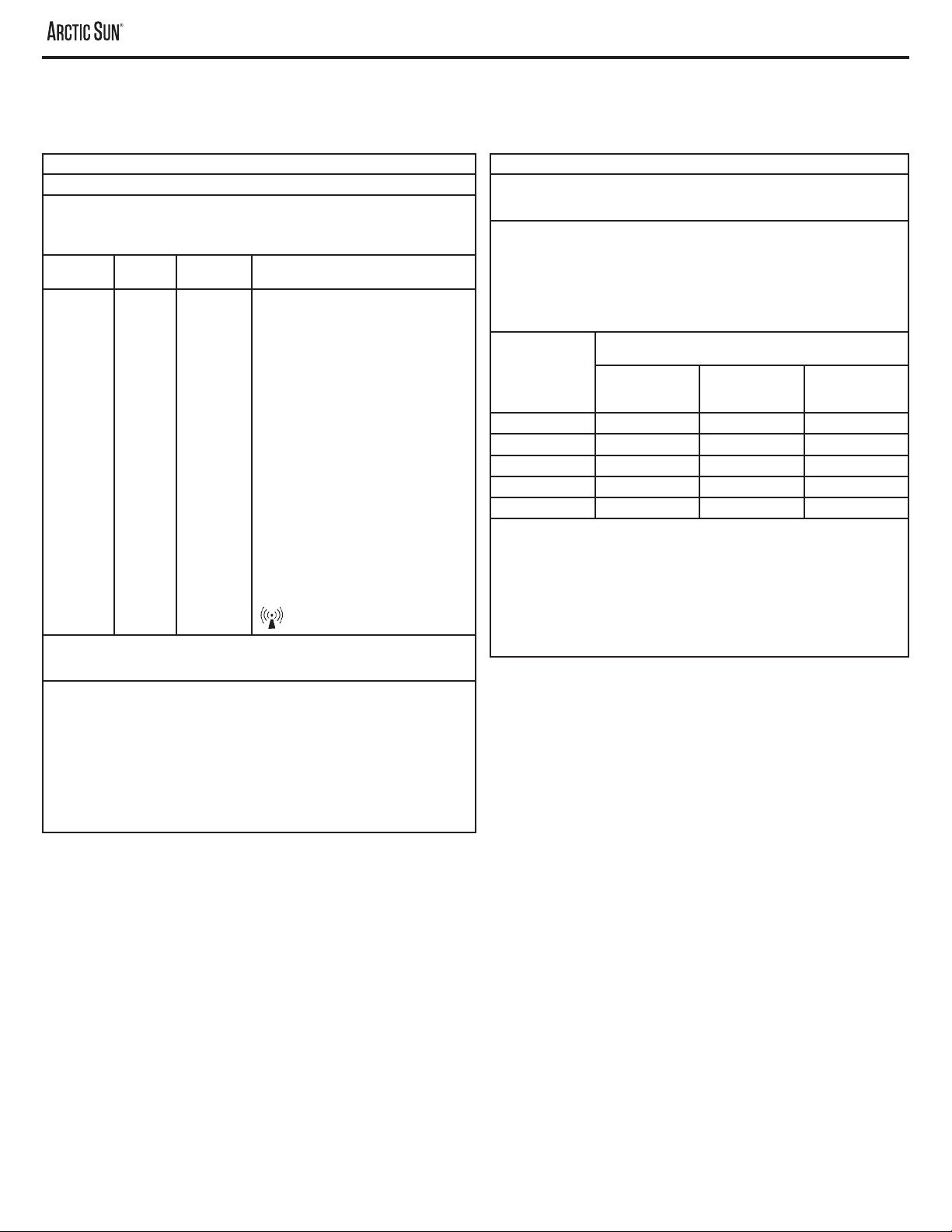
®P
Parameter
Therapy Modes
Sterile Water
3.5 liters
Water Flow Rate 5 liters per minute
Patient Probe Type YSI 400 Series compatible
Patient Temperature Inputs Patient Temp 1: control, monitor, alarm
Patient Temp 2: monitor, alarm
Patient Temperature Display Range
Patient Temperature Measurement Accuracy
Settling Time: ~4.5 hrs
Steady State Deviation: 0
Tracking Error: 0
Note: All values derived from testing in simulated use.
Water Temperature Display Range
High Water Temperature Limit
Low Water Temperature Limit
Sound Pressure Alarm Tone: 70dB to 80dB at 1 meter, repeats every 10 seconds
Alert Tone: 63dB to 71dB at 1 meter, repeats every 25 seconds
Mains Input
Operating Relative Humidity Range 5% to 70% non-condensing
Storage Relative Humidity Range 5% to 95% non-condensing
Operating Temperature Range
Storage Temperature Range
Atmospheric Pressure Range 60 kPa to 110 kPa
Dimensions Height: 35 inches (89 cm)
Width: 14 inches (36 cm)
Depth: 18.5 inches (47 cm)
Weight

10
TEMPERATURE MANAGEMENT SYSTEM
OPERATOR’S MANUAL
applied part.
Per ETL Intertek, models of the ®Temperature Management System that bear the ETL Monogram conform to AAMI
system is also listed.
®
and control.
Indicates electrical hazard
50°C
-30°C
95
05
Manufacturer
Date of Manufacture
Do not re-use.
Risk of overbalance due to pushing, leaning, resting, etc.
®Temperature Management System must be disposed of properly.
DO NOT dispose of into the garbage.
Appendix B: Symbols
The ®Temperature Management System Control module bears the following symbols:

11
ENGLISH
Appendix C: Electromagnetic Compatibility
Medical electrical equipment needs special precautions regarding
electromagnetic compatibility. Ensure that the ®Temperature
Management System is installed and used according to the electromagnetic
compatibility information provided. The following are guidance and
manufacturer’s declarations regarding electromagnetic compatibility for
the ®Temperature Management System.
Medivance (shown below) is not recommended. Use of unapproved
accessories or cables may result in increased emissions or in decreased
immunity of the ®Temperature Management System.
• If the ®Temperature Management System is used directly
observe the ®Temperature Management System device to
verify it operates normally in that environment.
Electrical Equipment.
Accessories and cables approved by Medivance for use with
the ®Temperature Management System
Part #
735-02
®735-03
735-04
735-05
735-06
735-52
®735-53
735-54
735-55
735-56
733-00
733-01
733-02
733-03
733-04
733-05
733-07
733-08
Transmission Interface Module (TIM) Kit 760-00
Transmission Interface Module (TIM) 761-00
762-00
The ®Temperature Management System is intended for use in the
®Temperature Management System should assure that it is used in such
an environment.
Emissions test Electromagnetic environment - guidance
RF emissions
Group 1 The ®Temperature
Management System uses RF energy
only for its internal function. Therefore,
its RF emissions are very low and are
not likely to cause any interference in
nearby electronic equipment.
Guidance and Manufacturer’s Declaration - Electromagnetic Emissions
Emissions Test Electromagnetic environment guidance
RF emissions
The ®Temperature
Management System unit is suitable
for use in all establishments other
than domestic, establishments and
those directly connected to the public
low-voltage power supply network
that supplies buildings for domestic
purposes.
61000-3-2
61000-3-3
The ®Temperature Management System unit is intended for use in the
®Temperature Management System unit should assure it is used only in
such an environment.
Immunity Test
level
Level
Intended
Electromagnetic
Environment
Electromagnetic
discharge (ESD)
±6kV contact
±8kV air
±6kV contact
±8kV air
Floors should be wood,
concrete or ceramic tile.
with synthetic material,
the relative humidity
should be at least 30%.
Electrical fast
±2kV for power
supply lines
±
output lines
±2kV for power
supply lines
±
output lines
Mains power quality
should be that of a
typical commercial or
hospital environment.
Surge
±
mode (line-line)
±2kV common
mode (line-earth)
±
mode (line-line)
±2kV common
mode (line-earth)
Mains power quality
should be that of a
typical commercial or
hospital environment.
Voltage
dips, short
interruptions and
voltage variations
on power supply
input lines
<5% UT (>95%
dip in UT) for
0.5 cycle
40% UT (60%
dip in UT) for
5 cycles
70% UT (30%
dip in UT) for
25 cycles
<5% UT (>95%
dip in UT) for
5 seconds
<5% UT (>95%
dip in UT) for
0.5 cycle
40% UT (60%
dip in UT) for
5 cycles
70% UT (30%
dip in UT) for
25 cycles
<5% UT (>95%
dip in UT) for
5 seconds
Mains power quality
should be that of a
typical commercial or
hospital environment.
If the user of the
®
Temperature
Management System
unit requires continued
operation during power
mains interruptions, it is
recommended that the
®
Temperature
Management System
unit be powered from
an uninterruptible
power supply with
run the unit for the
of interruption.
Power frequency
Power frequency
should be at levels
characteristic of a
typical location in a
typical commercial or
hospital environment.
Note: UT is the a.c. mains voltage prior to application of the test level.
12
TEMPERATURE MANAGEMENT SYSTEM
OPERATOR’S MANUAL
The ®Temperature Management System unit is intended for use in the
®Temperature Management System unit should assure it is used in such an
environment.
Immunity
Test
test level
Level
Intended Electromagnetic Environment
RF
4-6
Radiated
RF
4-3
3Vrms
150kHz to
80MHz
80MHz to
2.5GHz
3Vrms
150kHz to
80MHz
80MHz to
2.5GHz
Portable and mobile RF communications
equipment should be used no closer to
any part of the ®Temperature
Management System unit, including cables,
than the recommended separation distance
calculated from the equation applicable to
the frequency of the transmitter.
Recommended separation distance
rating of the transmitter in watts (W)
according to the transmitter manufacturer
and d is the recommended minimum
separation distance in meters (m).
as determined by an electromagnetic site
surveya, should be less than the compliance
level in each frequency range.b
Interference may occur in the vicinity
of equipment marked with the following
symbol:
NOTE 1 At 80MHz and 800MHz, the higher frequency range applies
NOTE 2 These guidelines may not apply in all situations. Electromagnetic propagation
a
cordless) telephones and land mobile radios, amateur radio, AM and FM radio
broadcast and TV broadcast cannot be predicted theoretically with accuracy. To assess
®
RF compliance level above, the ®Temperature Management System unit
should be observed to verify normal operation. If abnormal performance is observed,
additional measures may be necessary, such as re-orienting or relocating the
®Temperature Management System unit.
b
Recommended separation distances between portable and mobile RF
communications equipment and the ®Temperature Management
System unit
®Temperature Management System unit is intended for use in an
electromagnetic environment in which radiated RF disturbances are controlled. The
customer or the user of the ®Temperature Management System unit
can help prevent electromagnetic interference by maintaining a minimum distance
between the portable and mobile RF communications equipment (transmitters) and
the ®Temperature Management System unit as recommended below,
output power of
transmitter in watts
(W)
Separation distance according to frequency of transmitter in
meters (m)
150kHz to 80MHz
80MHz to 800MHz
800MHz to
2.5GHz
0.01 0.12 0.12 0.23
0.1 0.38 0.38 0.73
1.0 1.2 1.2 2.3
10 3.8 3.8 7.3
100 12 12 23
recommended separation distance d in meters (m) can be estimated using the
output power rating of the transmitter in watts (W) according to the transmitter
manufacturer.
NOTE 1 At 80 MHz and 800 MHz, the separation distance for the higher frequency
range applies.
NOTE 2 These guidelines may not apply in all situations. Electromagnetic
and people.
Appendix C: Electromagnetic Compatibility (continued)

13
ENGLISH

14
TEMPERATURE MANAGEMENT SYSTEM
14
GUIDE DE L’UTILISATEUR
TABLE DES MATIERES
Chapitre 1 – Mise en route ............................................................................... 15
Indications d’utilisation ....................................................................................... 15
Mises en garde et précautions ........................................................................... 15
Installation du système ...................................................................................... 16
Chapitre 2 – Traitement du patient ................................................................. 17
Placer les pads ™............................................................................... 17
™........................................................................ 17
Installation de la sonde de température .............................................................. 17
Sélection de traitement du patient ...................................................................... 17
................ 17
................... 17
Fin de traitement.................................................................................................. 18
Chapitre 3 – Paramètres de la normothermie................................................. 18
Paramètres de la normothermie ......................................................................... 18
Chapitre 4 – Paramètres de l’hypothermie .................................................... 18
Paramètres de l’hypothermie............................................................................... 18
............................................................... 18
Chapitre 6 – Alarmes et alertes ...................................................................... 19
Alarmes .............................................................................................................. 19
Alarmes de sécurité principales ......................................................................... 19
Alarmes non récupérables .................................................................................. 19
Alarmes récupérables.......................................................................................... 19
Alertes ................................................................................................................ 19
.............................................................. 19
Nettoyage et entretien ......................................................................................... 19
Entretien préventif ............................................................................................... 20
.......................................................................................... 20
Dépannage ......................................................................................................... 20
Étalonnage .......................................................................................................... 20
.......................................................... 20
Description technique.......................................................................................... 20
............................................................................ 20
®............ 21
Annexe B : Symboles et normes...................................................................... 22
................................................. 23
TEMPERATURE MANAGEMENT SYSTEM

1515
FRANÇAIS (FRENCH)
Chapitre 1 – Mise en route
Indications d’utilisation
Le système de gestion de la température ®est un système de
patients adultes et pédiatriques de tous âges.
Mises en garde
• Ne pas utiliser le système de gestion de la température ®
ou un incendie.
cathéters endocavitaires lorsque l’®est en cours d’utilisation.
• Risque d’électrocution et danger avec les pièces mobiles. Ne contient
aucune pièce réparable par l’utilisateur. Ne pas retirer les protections.
connecté à une prise équivalente marquée « usage hospitalier »
• Lors de l’utilisation du système de gestion de la température
®, il convient de remarquer que tous les autres systèmes
thermoconducteurs comme les couvertures à eau et les gels à base
gestion de la température ®
• Ne pas placer les pads ™ au-dessus des patchs de
de délivrance du médicament, ce qui risque de blesser le patient.
• Le système de gestion de la température ®n’est pas destiné
à être utilisé au bloc opératoire.
• La loi fédérale (États-Unis) restreint la vente de ce dispositif par ou sur
prescription d’un médecin.
• Utiliser uniquement de l’eau stérile. L’utilisation d’autres liquides peut
endommager le système de gestion de la température ®.
• Lors du déplacement du système de gestion de la température
®
• La surface du lit du patient doit être située entre 75 cm et 150 cm (30 et
60 pouces) au-dessus du sol pour assurer un débit adéquat et minimiser
les risques de fuites.
• Le clinicien est tenu de déterminer la pertinence des paramètres
personnalisés. Lorsque le système est hors tension, toutes les
d’utiliser les paramètres suivants : limite de température élevée de
paramètres de température du patient Patient alerte haute et Patient
alerte basse.
• L’opérateur doit surveiller en permanence la température du patient
de la température ®.
recommandé pour une utilisation prolongée. Il est conseillé à l’opérateur
• Le système de gestion de la température ®va monitorer et
de température connectée au système. Le clinicien est tenu d’installer
que la position de la sonde du patient au début de la procédure.
• Medivance fournit des simulateurs de température (résistances à valeur
de la température du patient lorsque le système est raccordé au patient.
une hypothermie ou une hyperthermie grave.
• Medivance recommande de mesurer la température du patient depuis
patient connectée à l’entrée de température 2 du système de gestion de
la température ®
périodiquement avec des instruments indépendants.
normative lors des décisions de traitement.
pas activées en mode Stop. La température du patient peut augmenter
ou diminuer avec le système de gestion de la température ®
en mode Stop.
et pendant l’utilisation. Si les pads ne s’amorcent pas ou qu’une fuite
d’air importante et continue est observée dans la ligne de retour du pad,
Les fuites peuvent entraîner un débit plus faible et potentiellement
réduire les performances du système.
• Le système de gestion de température ®doit être utilisé
™.
• Les pads
avec les systèmes de gestion de température ®.
• Les pads ™ sont non stériles et à usage unique. Ne pas
réutiliser ni stériliser. Dans un environnement stérile, les pads doivent
être placés selon les instructions du médecin, soit avant la préparation
stérile ou le drapage stérile. Les pads ™ ne doivent pas être
placés sur un champ stérile.
• Utiliser les pads immédiatement après ouverture. Ne pas stocker les
pads une fois que le kit a été ouvert.
• Ne pas placer les pads ™ sur une peau présentant des signes
d’ulcération, de brûlures, d’urticaire ou d’éruptions cutanées.
• Bien qu’aucune allergie à l’hydrogel n’ait été recensée, il convient
d’être prudent avec tout patient ayant un historique de sensibilité ou
d’allergies cutanées.
• Ne pas laisser l’eau de circulation contaminer le champ stérile lorsque
les lignes du patient sont déconnectées.
humides et adhérents. Remplacer les pads lorsque l’hydrogel n’adhère
plus uniformément sur la peau. Il est recommandé de remplacer les
• Ne pas percer les pads
pourrait réduire les performances.
•
™, surtout pour les patients présentant des risques élevés
de lésions cutanées. Des lésions cutanées peuvent se produire suite à
une action concomitante de la pression, de la durée et de la température.
Des lésions cutanées possibles comprennent notamment des ecchymoses,
des dilacérations, des ulcérations de la peau, des cloques et des nécroses.
Ne pas placer de sac de maintien ni d’autres équipements de contention
sous les pads ™. Ne pas placer de dispositifs de positionnement
sous les collecteurs ni les lignes des patients.
• La rapidité de changement de température et, éventuellement, la
L’application de traitement, le suivi et les résultats incombent au
médecin traitant. Si le patient n’a pas atteint la température cible dans
un délai raisonnable ou si la température cible du patient ne peut être
basses ou élevées pendant une longue durée, ce qui peut augmenter
du pad et les paramètres personnalisés soient corrects pour le patient
à 2,3 litres par minute et qu’une sonde de température du patient soit
placée au bon endroit. Pour le refroidissement du patient, s’assurer

16
TEMPERATURE MANAGEMENT SYSTEM
16
GUIDE DE L’UTILISATEUR
le traitement.
perfusion tissulaire médiocre ou une mauvaise intégrité de la peau
due au diabète, une maladie artérielle périphérique, un mauvais état
nutritionnel, la prise de stéroïdes ou de vasopresseurs à haute dose.
Si nécessaire, utiliser des dispositifs d’atténuation ou de réduction de
pression sous le patient pour protéger la peau.
• Ne pas laisser l’urine, des solutions ou d’autres agents antibactériens
s’accumuler sous les pads ™. L’urine et les agents
antibactériens peuvent pénétrer dans l’hydrogel du pad et causer des
blessures chimiques ainsi que la perte d’adhésion du pad. Remplacer les
pads immédiatement si ces liquides entrent en contact avec l’hydrogel.
• Ne pas placer les pads ™ au-dessus d’un pad
électrochirurgical de mise à la terre. La combinaison de plusieurs
sources de chaleur peut provoquer des brûlures de la peau.
™ et la peau du patient.
• Décoller délicatement les pads
de leur utilisation. Éliminer les pads ™ usagés conformément
• Le port de données USB doit être utilisé uniquement avec une clé USB
autonome. Ne pas connecter à un autre dispositif sous tension au cours
du traitement du patient.
• Les utilisateurs ne devraient pas utiliser de méthodes de nettoyage ou
proposées ne risquent pas d’endommager le matériel. Ne pas utiliser
d’eau de Javel (hypochlorite de sodium), car cela peut endommager
le système.
• Medivance ne sera pas responsable de la sécurité du patient ou de la
performance du matériel si les procédures d’utilisation, d’entretien, de
®
Installation du système
1) Déballer le module de commande du système de gestion de la
température ®et les accessoires.
2) Laisser le module de commande en position verticale pendant au
moins 2 heures avant de continuer la mise en place et la procédure
se stabiliser. Autrement, cela pourrait entraîner des dommages au
compresseur réfrigérant.
Connexions
1) Utiliser uniquement les câbles et accessoires approuvés par Medivance
avec le module de commande du système de gestion de la température
®
temp 1, le câble patient temp 2 (en option) et le tube de remplissage à
l’arrière du module de commande.
2) Brancher le cordon d’alimentation dans la prise murale. Placer le
système de gestion de la température ®de manière à ce
que l’accès au câble d’alimentation ne soit pas restreint.
Mise sous tension (On)
1) Mettre en marche (ON) en activant l’interrupteur.
de l’alarme de sécurité indépendante.
3)
Une option de formation au module pour le nouvel utilisateur est disponible
à partir de l’écran de démarrage.
4) Quand le test automatique est terminé, l’écran
du patient
1) Remplir le réservoir avec de l’eau stérile uniquement.
2) Quatre litres d’eau seront nécessaires pour remplir le réservoir lors de
l’installation initiale.
de la température ®à l’eau stérile.
4) Depuis l’écran presser soit le bouton
Normothermie soit Hypothermie, sous l’entête Nouveau patient.
5) Depuis l’écran de traitement Hypothermie, ou l’écran de traitement
Normothermie, presser le bouton .
6) L’écran va s’ouvrir. Suivre les instructions
à l’écran.
1) Mettre le module de commande sous tension (On).
2) Depuis l’écran , appuyer sur le
bouton Hypothermie Hypothermie.
3) Depuis l’écran de traitement Hypothermie, appuyer sur le bouton
Contrôle manuel pour ouvrir la fenêtre du Contrôle manuel.
Contrôle manuel
5) Appuyer sur le bouton pour lancer le Contrôle manuel.
Attendre au moins 3 minutes pour permettre au système de se stabiliser.
Interrupteur
Temp sortie
patient
Ligne de
distribution
d’alimentation
équipotentiel
Patient
Temp 1
Réducteur
de tension
Patient
Temp 2
patient
Logement tube
de remplissage
Tube de
Port
Ports de
vidange
Filtre à air
TEMPERATURE MANAGEMENT SYSTEM

1717
FRANÇAIS (FRENCH)
6) Surveiller le débit et la température de l’eau dans la zone d’état du
Système depuis l’écran de traitement Hypothermie.
9) Appuyer sur le bouton Arrêt.
10) Programmer le Contrôle manuel de la température cible de l’eau sur
11) Appuyer sur le bouton pour lancer le Contrôle manuel.
12) Surveiller le débit et la température de l’eau dans la zone d’état du
Système depuis l’écran de traitement Hypothermie
13) Appuyer sur le bouton Arrêt pour arrêter le Contrôle manuel.
14)
Appuyer sur le bouton Annuler pour fermer la fenêtre du Contrôle manuel.
15) Mettre le module de commande hors tension
Chapitre 2 – Traitement du patient
Placer les pads ™
Lire le mode d’emploi qui accompagne les pads ™.
Connexion des pads ™
Orienter les couleurs blanches et bleues du connecteur de ligne du pad et
pad, insérer le connecteur transparent de ligne du pad dans le collecteur de
mécaniques sur la surface de l’appareil avant utilisation.
température ®
de température du patient restant connectée au connecteur de température 1
du patient à l’arrière du module de commande. Tout instrument Yellow Springs
de la série 400 (YSI 400) disponible dans le commerce, compatible avec la
sonde de température du patient, peut être connecté au système de gestion de
la température ®
Utiliser l’écran pour démarrer un traitement
Nouveau patient, Continuer avec le patient actuel, ou accéder à l’écran de
.
Nouveau patient - Normothermie
Sélectionner Normothermie
indéterminée. Appuyer sur le bouton Normothermie
traitement Normothermie.
Nouveau patient - Hypothermie
Sélectionner Hypothermie pour réduire et maintenir la température du patient
bouton HypothermieHypothermie.
Hypothermie ou Normothermie)
.
Patient actuel
Le bouton Continuer avec le patient actuel et la date et l’heure où le
traitement du patient si le traitement d’un patient a été mis en pause dans
les 6 heures précédentes.
Appuyer sur le bouton Continuer avec le patient actuel reprend le traitement
du patient mis en pause.
Augmenter t° patient)
Le traitementest initié et géré, et la température du patient
est réglée automatiquement à une température cible réglée depuis la fenêtre
Contrôle patient sur l’écran de traitement Normothermie. La fenêtre Contrôle
patient
traitement normothermique.
1) Depuis l’écran , appuyer
sur le bouton Normothermie
Normothermie.
Contrôle patient.
3) Pour changer la température cible du patient, appuyer sur le bouton
Ajuster pour ouvrir la fenêtre.
4) Contrôle patient à :
5) Augmenter au taux de :
6) Appuyer sur le bouton Enregistrer pour enregistrer le paramètre et
fermer la fenêtre .
7) Appuyer sur , dans la fenêtre Contrôle patient pour démarrer
« Traitement commencé ». De plus, la fenêtre Contrôle patient et
Système de gestion de la température ®vont clignoter,
indiquant que le traitement est en cours.
Augmenter t° patient)
Le traitement est initié et géré, et la température du
patient est réglée automatiquement à une température cible réglée depuis
les fenêtres Baisser t° patient et Augmenter t° patient dans l’écran de
traitement Hypothermie.
La fenêtre Baisser t° patient
de refroidissement du patient, et le temps restant pour la phase de
refroidissement du traitement .
La fenêtre Augmenter t° patient
.
Pour débuter le traitement hypothermique :
Depuis l’écran appuyer sur le bouton
Hypothermie
1. Paramètres de refroidissement du patient
dans la fenêtre Baisser t° patient.
• Pour changer la température cible du patient, appuyer sur le bouton
Ajuster pour ouvrir la fenêtre .
• Baisser t° patient à
pour sélectionner la température cible du patient pour refroidir le patient.
• Baisser t° patient pendant
droit pour sélectionner la durée du refroidissement avant de débuter
• Appuyer sur le bouton Enregistrer pour enregistrer le paramètre et
fermer la fenêtre
dans la fenêtre Augmenter t° patient.
dans la
fenêtre Augmenter t° patient Augmenter t°
• Augmenter t° patient à :
pour sélectionner la température cible du patient.
• Augmenter au taux de :
•
Augmenter t° patient depuis : durant le refroidissement du patient, le
réglage de Augmenter t° patient depuis
Baisser t° patient.
Augmenter t° patient
depuisAugmenter
t° patient depuis
actuellement le patient. La température Augmenter t° patient depuis

18
TEMPERATURE MANAGEMENT SYSTEM
18
GUIDE DE L’UTILISATEUR
•
En utilisant la température Augmenter t° patient depuis, la température
Augmenter t° patient
•
Appuyer sur le bouton Enregistrer pour enregistrer le paramètre et fermer
la fenêtre
• Appuyer sur dans la fenêtre Baisser t° patient pour démarrer
“Traitement commencé”. De plus, la fenêtre Baisser t° patient et
®vont clignoter,
indiquant que le traitement est en cours.
soit Manuellement
selon le paramètre de dans les Paramètres
Hypothermie.
• Si est réglé sur , le processus
Baisser t° patient est terminé et que le minuteur est à zéro.
• Si est réglé sur Manuel, le processus de
est pressé dans
la fenêtre Augmenter t° patient. Le processus de refroidissement va
du
patient soit sélectionné. Une Alerte va se déclencher quand la durée
Baisser t° patient arrive à zéro. Lorsque le minuteur Augmenter t°
patient
Arrêt soit appuyé.
Une fois en Normothermie, le minuteur est remis à zéro et commence à
suivre la durée du traitement Normothermie.
Fin de traitement
•
Depuis l’écran de traitement Hypothermie ou de traitement Normothermie,
appuyer sur le bouton Arrêt
les pads.
• Appuyer sur le bouton Vider les pads, et suivre les instructions pour
purger les pads.
• Enlever soigneusement et doucement les pads de la peau du patient.
• Appuyer sur l’interrupteur .
Si l’électricité est coupée alors que l’interrupteur est en position On, une
l’utilisateur que le traitement peut avoir été accidentellement arrêté.
Chapitre 3 – Paramètres de la normothermie
Paramètres de la normothermie
Utiliser l’écran Paramètres de la normothermie
Ajuster à
droite du paramètre.
Paramètres de l’écran Paramètres de la normothermie :
• Préparation de l’eau
• Limite supérieure de l’eau
• Limite inférieur de l’eau
• Patient alerte haute
• Patient alerte basse
• Unités de température
• Réglage des unités de température
• Patient Temp 2
Pour accéder à l’écran des Paramètres de la normothermie :
1) Appuyer sur Ajuster dans la fenêtre Contrôle patient.
2) Appuyer sur le bouton Plus dans la fenêtre
3) L’écran Paramètres de la normothermie
4)
patient, appuyer sur le bouton Fermer. Pour les instructions d’enregistrement
des paramètres en tant que défaut du système, voir .
REMARQUE :
est correctement positionnée et correctement connectée au système.
première heure de traitement, le système déclenche l’alerte 116 – Patient
Si aucune suite n’est donnée à
l’alerte 116 après 5 minutes, le système déclenche l’alarme 117 – Patient
L’alarme 117 arrête le traitement
et une alarme sonore est émise. Après une intervention faisant suite à
l’alarme 117, le traitement doit être redémarré.
Chapitre 4 – Paramètres de l’hypothermie
Paramètres de l’hypothermie
Utiliser l’écran Paramètres de l’hypothermie
Ajuster à droite
du paramètre.
Paramètres de l’écran Paramètres de l’hypothermie :
Paramètres du traitement
• Début du refroidissement
• Préparation de l’eau
• Limite supérieure de l’eau
• Limite inférieure de l’eau
• Patient alerte haute
• Patient alerte basse
• Unités de température
• Réglage des unités de température
• Patient Temp 2
Pour accéder à l’écran Paramètres de l’hypothermie :
1) Appuyer sur Ajuster dans la fenêtre Baisser t° patient ou dans la
fenêtre Augmenter t° patient.
2) Appuyer sur le bouton Plus dans la fenêtre
ou dans la fenêtre .
3) L’écran Paramètres de l’hypothermie
du patient, appuyer sur le bouton Fermer. Pour les instructions
d’enregistrement des paramètres en tant que défaut du système,
voir .
REMARQUE :
correctement positionnée et correctement connectée au système. Si la
de traitement, le système déclenche l’alerte 116 – Patient température 1, variation
non détectée. Si aucune suite n’est donnée à l’alerte 116 après 5 minutes, le
système déclenche l’alarme 117 – Patient température 1, variation non détectée.
L’alarme 117 arrête le traitement et une alarme sonore est émise. Après une
intervention faisant suite à l’alarme 117, le traitement doit être redémarré.
Utiliser l’écran
Ajuster à droite du paramètre.
• Langue
• Format numérique
TEMPERATURE MANAGEMENT SYSTEM

1919
FRANÇAIS (FRENCH)
• Heure actuelle
• Format de date
• Date actuelle
Les fonctions suivantes peuvent être lancées depuis l’écran
• Téléchargement des données du patient : les données patient pour les
gestion de la température ®
lorsque le système de gestion de la température ®est
débranché, ou en cas de perte totale d’alimentation.
• Étalonnage
• Vidange
• Enregistrer tous les paramètres en tant que défaut
• Version du logiciel
• Dernier étalonnage
• Étalonnage suivant
1) Appuyer sur le bouton sur l’écran
traitement du patient.
2) L’écran
Pour accéder à l’écran de sélection du protocole supplémentaire :
®
supplémentaires.
Chapitre 6 – Alarmes et alertes
Le système de sécurité du système de gestion de la température ®
surveille en permanence l’état de l’appareil et le patient, et produit des
alarmes ou des alertes pour informer l’utilisateur des conditions pouvant
Alarmes et Alertes.
Une alarme avertit l’utilisateur que la condition peut potentiellement mettre
en danger le patient ou le dispositif. Une Alarme représente un état de
Une alerte informe l’utilisateur sur l’état du patient ou du dispositif sans
interrompre la procédure. Une Alerte représente un état de Priorité Moyenne
Alarmes
Une alarme est indiquée par un signal sonore qui se répète toutes les
du problème ou de la condition déclenchant l’alarme, et des solutions et
instructions de dépannage et de résolution de la condition. Si certaines
conditions d’alarme ne sont pas reconnues par l’opérateur en 2 minutes,
une sonnerie de rappel s’enclenchera. Tous les paramètres d’alarme restent
actifs en cas de panne générale de courant électrique.
gestion de la température
®
, il y a cinq alarmes de sécurité principales
qui mettront l’appareil en mode Arrêt
Echec auto-test du système Au dispositif ON
à chaque fois que le système de gestion de la température ®est
sécurité opposé. Si les systèmes de sécurité ne répondent pas de manière
Si une alarme se produit qui empêche la bonne utilisation de l’appareil ou le bon
traitement des patients (telle que l’une des cinq alarmes principales de sécurité
discutées ci-dessus), le système se mettra en mode Arrêt et ne permettra pas
Si cette situation se produit, cycler l’alimentation du dispositif (éteindre et
rallumer l’appareil). Si l’alarme se répète, contacter le support client.
récupérables. Si la condition qui a déclenché l’alarme n’est pas traitée et que
le problème persiste, l’alarme se répétera.
Si une alarme récupérable se produit :
1) Quand une alarme se produit, le dispositif se place en mode Arrêt.
3) Noter le numéro de l’Alarme.
4) Appuyer sur le bouton Fermer pour arrêter l’alarme.
soit réglée.
6) Une fois que vous avez annulé l’alarme, appuyer sur le bouton
dans la fenêtre de traitement pour redémarrer le traitement.
de gestion de la température ®vont clignoter.
7) Si le problème n’est pas résolu, contacter le support client.
Alertes
Les alertes sont signalées par un signal sonore qui se répète toutes les
d’alerte, le titre de l’alerte, une description du problème ou de la condition
déclenchant l’alerte, et des solutions et instructions de dépannage et de
résolution de la condition.
Si une alerte se produit :
2) Noter le numéro d’alerte.
3) Appuyer sur le bouton Fermer pour arrêter l’alerte.
soit réglée. Si le problème n’est pas résolu, contacter le support client.
®pour de plus amples informations sur les alarmes et
les alertes.
Nettoyage et entretien
sur le module de commande du système de gestion de la température
®tous les 6 mois au minimum. Il s’agit de nettoyer les surfaces
développement des micro-organismes dans le réservoir d’eau et le circuit
température ®pour de plus amples informations.
Surfaces externes
désinfectant conformément au protocole hospitalier.
Condenseur
• Un condenseur de refroidissement sale va réduire considérablement
la capacité de refroidissement du module de commande.
• Pour nettoyer le condenseur, essuyer la poussière de la grille

20
TEMPERATURE MANAGEMENT SYSTEM
20
GUIDE DE L’UTILISATEUR
votre établissement, retirer périodiquement la façade arrière et aspirer
ou brosser les ailettes du condenseur. Au minimum, les ailettes du
condenseur devraient être nettoyées annuellement. Les activités de
Inspection du dispositif
Réapprovisionnement de la solution de nettoyage interne
Pour réapprovisionner la solution de nettoyage interne :
1) Vidanger le réservoir.
module de commande. L’eau va se vider de manière passive dans
le sac.
2) Remplir le réservoir.
• Depuis l’écran de traitement Hypotermie ou l’écran de traitement
Normothermie, appuyer sur le bouton Remplissage du réservoir.
• L’écran Remplissage du réservoir va s’ouvrir. Suivre les instructions
à l’écran.
de la température ®à la première bouteille d’eau stérile.
• Le processus de remplissage s’arrête automatiquement lorsque
• Quand le processus de Remplissage du réservoir est terminé,
l’écran va se fermer.
Le fait d’utiliser le système de gestion de la température ®pendant
plus de 2000 heures sans procéder à un entretien préventif peut entraîner
une défaillance de certains composants du système et empêcher ce dernier
de gestion de la température ®.
Pour de plus amples informations, veuillez consulter
manuals, composer le +1-800-526-4455 ou contacter votre représentant
®
.
1. Mettre le système sous tension.
2. Depuis l’écran Sélection de traitement du patient, appuyer sur le bouton
Hypothermie.
3. Depuis l’écran de traitement Hypothermie, appuyer sur le bouton de
commande Contrôle manuel pour ouvrir la fenêtre Contrôle manuel.
4. Régler la température cible de l’eau du Contrôle manuel
durée sur 30 minutes.
5. Brancher une dérivation à une série de ports de lignes de distribution
6. Appuyer sur le bouton Aide, puis appuyer sur le bouton Index de
l’aide. Sélectionner la rubrique Entretien et service et la sous-rubrique
Diagnostic du système, puis appuyer sur le bouton
que la pression d’entrée est comprise entre -7 ± 0,2.
7. Répéter l’opération pour toutes les soupapes. Si la pression d’entrée
est connectée.
8. Veiller à retirer la dérivation avant de remettre le dispositif en service.
Mise à jour du logiciel
de commande.
dans le port USB de l’appareil sous tension (On).
Pour installer la mise à jour du logiciel :
1) Insérer la clé USB dans le port USB.
du logiciel, et disparaîtra lorsque le processus d’installation du logiciel
sera terminé.
d’information sur le produit, y compris les listes de pièces détachées et les
réparer ces pièces et l’équipement que Medivance estime être réparables.
Étalonnage
Voir le manuel de l’utilisateur du système de gestion de la température
®pour les instructions et besoins d’étalonnage. Un étalonnage
est recommandé après 2000 heures de fonctionnement ou 250 utilisations,
selon ce qui se produit en premier.
Le système de gestion de la température ®est un dispositif
®consiste en un module de commande et des
pads ™à usage unique.
Une sonde de température du patient connectée au module de commande
fournit les informations de température du patient à un algorithme de
de l’eau circulant pour atteindre une température cible du patient
Le système de gestion de la température ®fait passer l’eau à une
à travers les pads ™à environ 0,7 litres par minute par pad.
Le module de commande du système de gestion de la température
®
Le module de commande du système de gestion de la température
®
également conformes à cette norme. Il n’y a pas de mode de défaillance
connu dans le module de commande du système de gestion de la
température ®associé à des interférences électromagnétiques
provenant d’autres dispositifs. Voir le manuel d’entretien du système
de gestion de la température ®pour la déclaration complète
concernant la compatibilité électromagnétique.
Conditions environnementales
Variations de température
Fonctionnement : ...................................
Entreposage : ........................................
la capacité de refroidissement du système de réfrigération et par
conséquent sa capacité à refroidir un patient est compromise.
Fonctionnement :.....................................................5% to 70%
Entreposage : ..........................................................5% to 95%
Pression atmosphérique de fonctionnement : .........60 kPa à 110 kPa
Élimination
local ®
TEMPERATURE MANAGEMENT SYSTEM
This manual suits for next models
1
Table of contents


