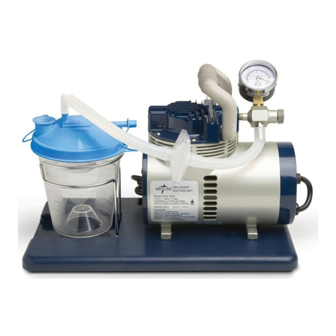
Medline Hemo-Force User manual

Hemo-Force®
Intermittent DVT Pump
Generation 2
MDS600INT2
User Manual
(English)

2
Table of Contents
Introduction 3
Intended Use 3
Warnings & Cautions 4
General Safety 6
Control Panel Features 7
Operating Instructions 10
Operating Functions 13
Contraindications & Cautions 14
Cleaning 15
Warning Troubleshooting Guide 16
Technical Data 17
Electromagnetic Compatibility 19
Symbols Used 24
Expected Service Life 25
Warranty 25
Français 27
Español 53

3
Introduction
The Hemo-Force® is an Intermittent Pneumatic Compression System
that counteracts blood stasis and coagulation changes; two of the three
major factors that promote deep vein thrombosis (DVT) a potentially
life-threatening condition which can lead to pulmonary embolism.
The Hemo-Force® is a non-invasive mechanical prophylactic system
that massages the feet or legs in a wavelike, milking motion that
promotes blood flow and deters thrombosis, helping to empty pooled
or static blood from the valve cusps of the femoral vein. Fibrinolytic
activity is increased stimulating the release of a plasminogen
activator. This therapy typically complements other prophylactic
measures, such as anti-embolic stockings and anticoagulants.
Some exciting features include:
• User-friendly master control unit that is designed so that its functions
are self-explanatory
• Power button (ON/OFF)
• An alarm displays a fault status with an audio alarm and LCD display
• LCD display that can monitor errors, statuses, and pressure values of
the device
• Timer indicator that reflects each hour of compression
• A button (RESET) that causes a counter to take the state corresponding
to a specified initial number (zero)
• Battery indicator that can show remaining battery status
• Unique hanging bracket that provides easy attachment
Intended Use
The system consists of an air pump and single-patient-use compression
garment – one for the foot, one for the calf and one for the thigh. The air
pump and compression garment may be used on one lower extremity.
The inflation pressure settings are pre-set by the manufacturer and
cannot be changed. The compression level for the foot garment is
120mmHg (16kPa). The compression level for the calf and thigh garment
is 40mmHg. The garment inflates and maintains compression for 12
seconds. Then, the garment deflates for a period of 48 seconds. As the
garment inflates, it compresses the foot, calf or thigh which augments
venous blood flow, thereby reducing stasis. This process also stimulates
fibrinolysis; thus, reducing the risk of early clot formation. Regularly
check the system while in use, assuring pump operation and garment fit.

4
Warnings & Cautions
CAUTION: READ ALL INSTRUCTIONS BEFORE USING THE APPLIANCE
WARNING: To reduce the risk of burns, electrocution, fire, or injury
to persons:
1. Keep the pump and garment away from sources of liquid and open
flames.
2. Keep the pump and garment away from sharp objects.
3. If pain, irritation, numbness, swelling, or redness occurs discontinue
use and contact a healthcare professional.
4. The pump should always be used in conjunction with hospital policy.
5. The pump should only be repaired including the installation or
replacement of the battery pack by a qualified and authorized
professional. The product has no user/operator serviceable parts.
6. Do not drop the pump or store it in direct sunlight or extremely cold
conditions.
7. Do not use the system in the presence of any flammable gases (such as
Anesthetic Agents).
8. During DIP or power interruption the device would stop functioning
and fail the intended use. Please ensure the device is used with a
stable power/Uninterruptible Power Supply or battery power to
prevent this scenario. Do not obstruct the mains plug or position the
equipment where the connection to the mains line can be accidentally
disconnected.
9. No modification of this equipment is allowed.
10. Power cable & pump shall be placed at the foot-side of the patient to
prevent any risk of strangulation due to cable.
11. Never operate this product if it has a damaged cord or plug, not working
properly, having been dropped or damaged, or dropped into water.
Return the product to a service center for examination and repair.
12. Use the product only for its intended use as described in this manual.
Do not use attachments not recommended by the manufacturer.
13. Do not modify the product without the authorization of the
Intended Use & Operator
Please note: The intended user (patient) of the system includes children, adolescents,
and adults, but they cannot be the operator.
The intended operator is a health care professional. The system should only be
operated by trained health care professionals.
The system can only be used under the instruction from the physician in hospital.

5
manufacturer. Failure to do so may cause exposure to hazards.
14. Maintain the device regularly. When the device needs repair or
maintenance, please turn off the power first, remove it from the
patient, and do not use the device.
15. Keep the cord away from heated surfaces and anywhere hard to
unplug with the device like on the shelves, in a wardrobe or the
socket on the ceiling.
16. This device can be used in a professional healthcare environment.
17. Careful consideration of this information is essential when stacking
or collocating equipment and when routing cables and accessories.
NOTE: If you are unsure of any contraindications, please refer to the
patient’s physician before using the Hemo-Force® Intermittent Pneumatic
Compression System.

6
General Safety
These usage and safety guidelines are IMPORTANT!
Please follow them carefully.
General Use
Carefully unpack the contents of the pump package.
Connect the Pump to a proper power source.
Storage Environment Specification
It is recommended that the following guidelines be used whenever
the system is being stored or transported to another location:
Temperature limitations: 5°C ~ 60°C
Relative humidity: 30% ~ 75%
Pump
Check the power cord and plug for abrasions and excessive wear.
Plug in the unit and verify airflow from the hose connection ports.
Place in a dry storage area when not in use.

7
Control Panel Features
Icon Indication
A
Status:
Int: Initialization
LEG: Calf/Thigh
Ft: Foot
GE: Garment Error Alarm
F: System Failure Alarm
HI: High Pressure Alarm
LO: Low Pressure Alarm
BInitialization Timer Pressure
CTimer
DTimer Reset
EPower Button
FMaintenance
GMute
HCaution
IBattery
JGarment Configuration
KAlarm Mute
Timer Reset
Timer Reset Fr
)
EKJIHGF
DCBA

8
Components
Garment
Air Hose

9
Connection Instruction
Packing List
Package 1 of 1 contains:
1 – Hemo-Force® Pump
1 – Air Tube Pair
1 – User Manual
Step 1 — Connect the air hoses to Control Unit.
Step 2 — Connect the air hoses to Garments.

10
Operating Instructions
The Hemo-Force® System is easy to set up. The following steps should
be followed. Please read this instruction manual in its entirety before
setting it up.
1. Once the pump and garments have been removed
from their packaging plug the pump into an
electrical outlet. DO NOT TURN IT ON YET.
2. Position the pump on any flat surface or suspend the
pump at the foot of the bed using the swing-out hooks.
Do not hook on a slanted or curved surface.
3. Measure the patient’s calf/foot/thigh circumference
at the widest point to ensure proper fit.
4. Application of the Calf/Thigh garment(s).
a) Garments come in identical pairs and may be used on either leg.
b) Unfold the garment and lay the unfolded garment on
a flat surface with the inside of the garment facing up.
c) Position the garment at the appropriate ankle or knee landmark.
d) Place the patient’s leg on the garment lining, and
position the back of the knee over the popliteal
opening in the case of thigh high garment.
e) Starting at the side opposite the air hose, wrap the main
flap of the garments snugly around the patient’s leg.
f) Fasten the garment securely with the hook and loop fasteners
starting at the ankle and then move to the calf and/or thigh.
Secure with tabs starting at the bottom tab. Check that none
of the hook and loop flaps hang off the end of the garment
(the entirety of the hook and loop area is secured to the
garment). The garment should fit securely but not tightly
around all parts of the patient’s leg. Confirm garment is
properly sized by checking that the index line falls between
the range markers. Follow the instructions and select the
next size up or down if the index line falls out of range.
g) Use the “two-finger” rule to check that the correct fit
is used. Insert 2 fingers horizontally (with palm up and
both fingers touching the patient’s leg) in between
the garment and the patient. This practice should be
done at both the top and bottom of the garment.
h) Using the same procedures apply the second model garment
if needed. If only one garment is to be used, simply leave the
unused air outlet on the pump free (no garment attached).

11
5. Application of the Foot garment(s).
a) Foot garments come in identical pairs and
may be used on either foot.
b) Place the garment on the patient’s foot ensuring
the hook and loop attachments are visible.
c) Ensure a snug fit by placing two fingers around the back of
the garment to ensure the garment is not too tight. Routinely
inspect the patient’s feet once compression commences.
d) Using the same procedures, apply the
second model garment if needed.
e) If only one garment is to be used simply leave the unused
air outlet on the pump free (no garment attached).
6. Air hose(s) are required to connect the garment(s) to the pump
and are provided separately. Attach the garment(s) to the
air hose(s) using the connectors. Each tube has a male-end
connector at one end and a female connector at the other.
The female end will fit the male end on the garment.
7. Attach the other end(s) of the air hose(s) (male end) to the
female connector(s) on the pump. If you need to disconnect
the tubing, pull on the connector to disconnect.
8. Press and hold the power button to turn the pump on when
the air hose(s) and the garment(s) are properly connected.
9. The pump will automatically detect single/dual and leg (calf/
thigh)/foot models of garment(s) during the initialization process
lasting approximately 10 seconds. Highlighted graphics will
display how many feet versus leg garments are attached.
10. After initialization, check to confirm the screen
graphic(s) displays the desired settings.
11. To activate the timer, turn the pump on and timing will commence.
The timer will reflect minutes of compression. When compression is
interrupted and the pump is turned off, the timer will suspend timing
until the patient is reconnected to therapy and therapy is continued.
12. To reset the timer press “TIMER RESET” for
5 seconds and it will reset itself.
13. To turn the pump off, hold the POWER button for 1 second.
14. To disconnect the device, remove the plug from the electrical outlet.
15. To remove the garments, pull the connectors apart.
Operating Instructions (cont)

12
Recommendations during operation
• Avoid placing the tubing and/or any connections or components
under the patient as this may negatively impact the effectiveness
of the pump and/or cause a skin integrity issue for the patient
• Make sure that there are no kinks in the tubing and that the
connectors are properly locked.
• Never apply or remove the garments while inflated as this may
cause damage to the garment.
• The parts and/or accessories supplied are specifically designed
for use with Hemo-Force® Control Unit. Use of other products in
conjunction with the system is not recommended.
• Respond to the instrument alarms appropriately and follow the
manufacturer’s recommendations.
• After initialization, ensure highlighted graphics displayed match
the desired settings.

13
Operating Functions
1. Battery Option (Battery sold separately)
i. This device has a Lithium battery option that can serve
as a backup. The device constantly monitors the outer AC
electric power supply. In the case of a power failure, the
pump will switch to battery operation automatically.
ii. The “Battery Indicator” indicates the battery
capacity status as illustrated.
iii. Under normal conditions a fully charged battery will last
approximately 4 hours of continuous operation. It may take
up to 16–20 hours to fully charge a depleted battery. When
battery is charging, a battery icon will appear on the LCD
screen, and the power button will illuminate in green.
iv. The pump will show a flashing light from the “Battery Indicator”
and trigger the audio alarm to give a low battery warning
15 minutes before the pump automatically shuts down.
CAUTION: When using a pump with the battery in a normal
situation, if a pump is turned off immediately after losing the AC
power, it might be the battery is out of power or failed. In this
case, connect the pump to the AC power to charge the battery
for 16-20hours. If the pump still cannot be powered on by the
battery, it means that the battery is out of order. Please contact
a qualified and authorized professional to replace the battery.

14
Contraindications & Cautions
Do not use the Hemo-Force® where increased venous or
lymphatic return is not desired. The Hemo-Force® Intermittent
Compression System could be contraindicated and should not be
used by persons with known or suspected deep vein thrombosis,
pulmonary edema, congestive heart failure, severe arteriosclerosis,
thrombophlebitis, or active infection. Do not use it on persons
with painful and sensitive extremities, where the garment will
interfere with gangrenous limbs, on persons with vein ligation
or recent skin grafts, or extreme deformity of the leg.
NOTE: If you are unsure of any contraindications, please refer to the
patient’s physician before using the Hemo-Force® Intermittent Pneumatic
Compression System.
2. Indicator Light
i. Green: Power button illuminated in green to indicate the control
unit is running on AC power.
ii. Amber: Power button illuminated in amber to indicate the control
unit is running on battery power.
iii. Flashing Amber: Flashing Alarm Mute button in amber to indicate
a fault has been detected followed by an audio alarm.
3. Audible Alarm
Press the alarm mute button and the audible alarm
can be temporary muted. The audible alarm will go off
again after 10 minutes if the error still persists.

15
filter
Cleaning
Caution
•Do not use phenol-based cleaning solutions.
•Switch off the electrical supply to the pump and disconnect the
power cord from the main supply before cleaning and inspection.
The pump: The casing of the pump is manufactured from ABS
plastic, which is a combination of different resins that is hard and
durable through a broad range of temperatures. If soiled, it can
be wiped down with a sodium hypochlorite solution to dilution of
1000ppm or with any EPA-approved hospital-grade cleaner.
The control unit (face) should also be cleaned weekly using a damp soft
cloth and mild detergent.
The garment: It is a single-patient use garment.
Do not wash or clean. Discard after use.
Replace air filter: Please replace the filter regularly, depending on the
air quality

16
Warning Troubleshooting Guide
Indicates the error information for Hemo-Force®, these include: Lo,
Hi, GE and F.
Alarm
Codes Fault Type Description Troubleshooting
LO Low Pressure 1. Leg is less than
40mmHg pressure;
foot pressure is less
than 120mmHg after
2 consecutive cycles.
2. Air hose is
disconnected from
garments.
1. Check connection
between garment and
air hose.
2. Check for leaks in the
garments or air hose set
and replace if faulty.
3. Turn the pump off and
restart.
4. Refer to a professional
for service if problem
persists.
HI High Pressure 1. Air hose is kinked.
2. Leg pressure is more
than 40mmHg; foot
pressure is more than
120 mmHg after 2
consecutive cycles.
1. Check air hose set for
any kinks.
2. Refer to a professional
for service if problem
persists.
GE Garment Error 1. Garment is not
connected to air hose
during start up.
2. Garments are not
fully deflated during
each restart.
3. The initialization
failed due to a
possible blockage in
air hose/garment
connectors.
1. Attach garments to
air hose and restart.
2. Ensure garments are fully
deflated before restart.
3. Check connectors for any
blockage and restart.
4. Refer to a professional
for service if problem
persists.
FSystem Failure 1. Loose air hose
connection on both
ports at pump.
2. Pressure is lower than
set pressure after 10
consecutive inflations.
3. Pressure is greater
than set pressure
after two inflations.
4. Electrical malfunction.
1. Check air hoses
connections.
2. Turn the pump off and
restart.
3. Refer to a professional
for service if problem
persists.

17
Technical Data
Model No. Hemo-Force®
Item Name Intermittent DVT Pump
Ref No. MDS600INT2
Size 7.54”x 5.12”x7.95”
Weight 5 lbs (2.8 Kg) - without battery
Pressure Range Calf/Thigh Garment: 40 mmHg +10/-5mmHg (5.3kPa
+1.3kPa/-0.7 kPa)
Foot Garment: 120 mmHg +10/-5 mmHg (16 kPa +1.3/-
0.7 kPa)
Input Rating AC 100-240V, 50/60Hz, 0.6~0.4A
Power Cable 15ft, non-shielding, AC powered (USA)
Fuse Rating T1AH 250V
Classification Class II, Type BF
Not AP or APG type
Ingress Protection IP22
Operation Humidity 30–75%
Operation Temperature 15–35°C
Operation Atmospheric
Pressure Range
700 hPa to 1060 hPa
Mode of Operation Continuous
Applied Part Garment
Battery Pack Model.
(optional)
MDS600BAT (14.4 Vdc, 2200 mAh / 31.68 Wh
Lithium-ion rechargeable battery pack)

18
Hemo-Force®Pump & Optional Accessories
The list is as follows:
Garments for Hemo-Force®Pump
Model Name Size
MDS601PD1 Intermittent Garment Knee-High Small Long, 1pr/Ea
MDS601PD2 Intermittent Garment Knee-High X-Small Short, 1pr/Ea
MDS601PD3 Intermittent Garment Knee-High X-Small Long, 1pr/Ea
MDS601P2 Intermittent Garment Knee-High Small, 1pr/Ea
MDS601M2 Intermittent Garment Knee-High Medium, 1pr/Ea
MDS601L2 Intermittent Garment Knee-High Large, 1pr/Ea
MDS601B2 Intermittent Garment Knee-High X-Large, 1pr/Ea
MDS630S2 Intermittent Garment Thigh-High Small, 1pr/Ea
MDS630M2 Intermittent Garment Thigh-High Medium, 1pr/Ea
MDS630L2 Intermittent Garment Thigh-High Large, 1pr/Ea
MDS630B2 Intermittent Garment Thigh-High X-Large, 1pr/Ea
MDS6202 Intermittent Foot Medium, 1pr/Ea
MDS620L2 Intermittent Foot Large, 1pr/Ea
Hemo-Force® Pump
Model Name Size
MDS600INT2 Second Generation DVT Pump
Tubing for Hemo-Force® Pump
Model Name Size
MDS610S2 Intermittent Tubing 5 Foot (1.5 Meters)
MDS610L2 Intermittent Tubing 10 Foot (3 Meters)
Battery for Hemo-Force® Pump
Model Name Size
MDS600BAT Battery For DVT Pump

19
Electromagnetic Compatibility
That portable RF communications equipment can affect medical
electrical equipment. We recommend a safety distance no closer
than 30 cm (12 inches) to any part of the DVT Pump, including
cables and at least 3.3 feet (1 meter) for sensitive equipment.
Medical electrical equipment needs special precautions regarding EMC
and needs to be installed according to the EMC information provided.
Manufacturer’s Declaration – Electromagnetic Emissions
The Hemo-Force® is intended for use in the electromagnetic environment (for professional
healthcare) specified below. The customer or the user of the Hemo-Force® should ensure
that it is used in such an environment.
Emission test Compliance Electromagnetic
environment-guidance
(for professional healthcare
environment)
RF emissions
CISPR 11
Group 1 The Hemo-Force® uses RF
energy only for its internal
function. Therefore, its RF
emissions are very low and
are not likely to cause any
interference in nearby
electronic equipment.
RF emissions
CISPR 11
Class A The Hemo-Force® is suitable
for use in all establishments
other than domestic and those
directly connected to the public
low-voltage power supply
network that supplies buildings
used for domestic purposes.
Harmonic emissions
IEC 61000-3-2
Not applicable (120V)
Class A (230V)
Voltage fluctuations/
flicker emissions
IEC 61000-3-3
Not applicable (120V)
Compliance (230V)
CAUTION: This equipment is not intended for use in residential
environments and may not provide adequate protection to radio
reception in such environments.

20
Manufacturer’s Declaration – Electromagnetic Immunity
The Hemo-Force® is intended for use in the electromagnetic environment (for professional
healthcare) specified below. The customer or the user of the Hemo-Force® should assure that it is
used in such an environment.
Immunity test IEC 60601 test level Compliance level Electromagnetic
environment-guidance (for
professional healthcare
environment)
Electrostatic
discharge (ESD)
IEC 61000-4-2
Contact: ±8 kV
Air±2 kV, ±4 kV, ±8
kV, ±15 kV
Contact: ±8 kV
Air±2 kV, ±4 kV, ±8
kV, ±15 kV
Floors should be wood,
concrete or ceramic tile. If
floors are covered with
synthetic material, the
relative humidity should be
at least 30%.
Electrical fast
transient/burst
IEC 61000-4-4
±2 kV for power
supply lines
±1 kV for input/
output lines
± 2kV for power
supply lines
Not applicable
Mains power quality
should be that of a typical
professional healthcare
environment.
Surge
IEC 61000-4-5
± 0.5 kV, ±1 kV
line(s) to line(s)
± 0.5 kV, ±1 kV,± 2kV
line(s) to earth
± 0.5kV, ± 1kV line(s)
to line(s)
Not applicable
Mains power quality
should be that of a typical
professional healthcare
environment.
Voltage Dips,
short interrup-
tions and voltage
variations on
power supply
input lines
IEC 61000-4-11
Voltage dips:
0 % UT; 0,5 cycle
0 % UT; 1 cycle
70 % UT; 25/30
cycles
Voltage
interruptions:
0 % UT; 250/300
cycle
Voltage dips:
0 % UT; 0,5 cycle
0 % UT; 1 cycle
70 % UT; 25/30
cycles
Voltage
interruptions:
0 % UT; 250/300
cycle
Mains power quality
should be that of a typical
professional healthcare
environment. If the user of
the Hemo-Force® requires
continued operation during
power mains interruptions,
it is recommended that the
Hemo-Force® be powered
from an uninterruptible
power supply or a battery.
Power frequency
(50, 60 Hz)
magnetic field
IEC 61000-4-8
30 A/m
50 Hz or 60 Hz
30 A/m
50 Hz and 60 Hz
The Hemo-Force® power
frequency magnetic fields
should be at levels
characteristic of a
typical location in a typical
professional healthcare
environment.
NOTE: UT is the a.c. mains voltage prior to application of the test level.
This manual suits for next models
1
Table of contents
Languages:
Other Medline Water Pump manuals
Popular Water Pump manuals by other brands

Agilent Technologies
Agilent Technologies TwisTorr 304 FS Quick reference guid

Pentair
Pentair PINNACLE Installation, operation & service manual

Marineland
Marineland MAXI-JET Quick setup guide

BLACKMER
BLACKMER CRL4A Installation, operation and maintenance instructions

DAB
DAB evoplus Instruction for installation and maintenance

ProMinent
ProMinent Sigma/3 Basic S3Ba Series operating instructions