MegaLite Deco Drive IP User manual
USER MANUAL
Table of Contents
Safety Information 2
What Is Included 2
Specifications 3
Main Power Connection 4
DMX-512 Connection 4
Output Connection 4
Control Board 5
DMX Profile 7
Size & Weight 8
Cleaning & Maintenance 9
Parts List 9
Warranty 10
Customer Service 11
Customer Support 11

Check that the unit has not been damaged during transport
Protection Against Fire
1. Maintain a minimum of 1 foot distance from any type of flame.
2. Do Not install the unit too close to a heat source.
3. Make sure cables are properly secured away from movement.
4. Maximum surface operating temperature is 148°F
5. Unit must not be left on for long periods of time.
Protection Against Electrical Dangers
1. Disconnect power before servicing.
2. For connection to main power supply proceed to page 4.
3. This unit must be earthed. (electronically grounded)
4. The Unit must be installed in a well ventilated area.
5. Be sure ventilation slots are not blocked.
Protection Against Mechanical Hazards
1. Unit surface may reach high temperature. Allow about 5 minutes after powering the unit before
moving.
2. Use secondary support when installing the unit.
2
What is Included
1pc Deco Driver IP
1pc True One Type Power Cable
1pc User Manual

3
Specifications
Part Numbers
Fixture
5070– Deco Driver IP
Mechanical Specifications
Fastening System: M10 Clamp mount tread, Mounting hole, Accessory Din Rail Mounts
Display: Digital
Power Connection: True One (type) Cable Mounted to Nema 5-15 plug.
Housing: IP rated extrusion
DMX Connection: 5 Pin XLR in and out & Wireless Solutions Wireless Connection Receiver
Output Connection: 4 X IP66 rated 5 pin Connection (CON-COL-DC5)
Electrical Specifications
Power Input: 90-264VAC 50/60 Hz
Output Ports 4
Power Per Output 100W
Total Max Power: 580W
Operating Power Consumption: 3.29 Amps
384 Watts
Ballast: Electronic: Mean Well UHP-500-24
Output: 24V
Drive Method: Constant Voltage
Working Ambient Temp: 24°f -148°f
Cooling: Internal Fan
Refresh: 4,000Hz
Protocol: DMX 512
DMX 5 Modes:
1 Channel Mode Dimmer
2 Channel Mode Warm White, Cool White
3 Channel Mode R, G, B
4 Channel Mode R, G, B, W
7 Channel Mode Dimmer R, G, B, W, Strobe, Macro
Operating Mode: 17 Pre Programs, Stand alone via Display, Manual Setting
Control & Programming

4
Main Power Connection
Caution!
1. Do not connect fixture to a dimmer system.
2. This unit has Auto switching power supply. It will respond to 90V to 264V automatically
3. This unit must be earthed. (electronically grounded)
4. There is no serviceable parts inside. Return to manufacture for factory service
The occupation of the connection-cable is as follows:
DMX-512 Connection
The fixture is equipped with 5 pin XLR Sockets for DMX input and output. The sockets are wired in parallel. Only use a
shielded twisted pair cable designed for RS-485 and 5 pin XLR plugs and connectors in order to connect the controller
with the driver or the driver with another. If unit is installed outdoor make sure to use outdoor rated cable.
DMX 5 Pin —Input / Output 1. Ground
2. Signal (-)
3. Signal (+)
1
3
2
4
5
This fixture is equipped with an electronic power supply that will let the unit operate from 90V to 264V from 50Hz to 60Hz
Cable (USA) Cable (EU) Pin 110V
Black Brown
White
Green
Light Blue
Yellow/Green
Live
Neutral
Ground
L
N
220V
L
L
RJ45 8 Pin
Output Connection
Deco Driver IP is designed to be used as a driver for Constant Voltage lighting fixtures. There are many fixtures a Deco
Driver can control . Each of the 4 output can be individually controlled and addressed to use the same or different fixture
per each output. The Deco Lighting fixture manual will give you the information with power link limitations and control
type for that unit.
Fixtures that require RJ45 connection will not be able to use this driver
Use AWG 22 or thicker cable for connection with fixture. Cables exceeding 100ft will have voltage drop. Voltage drop
will result in intensity drop. Thicker AWG cable will allow for longer cable runs. Please consult an electrician for more
information.
4 Ch Fixtures
DMX Control Mode
4 or 7CH
3 Ch Fixtures
DMX Control Mode
3 CH
2 Ch Fixtures
DMX Control Mode
2 CH
1 Ch Fixtures
DMX Control Mode
1 CH
1
2
3
4
5
1
2
3
4
1
2
3
4
5
1
2
3
4
5
Black
Red
Green
Blue
White
Black
Red
Green
Blue
1
2
3
4
5
6N/A 1
2
3
4
5N/A
6N/A
Black
WW
WW
CW
CW
1
2
3
4
5
6N/A
Black
White
White
White
White
1
2
3
4
5
6N/A
Each Output Port is capable of up to 100W output with a total of 400W total power consumption for
all outputs
Important!

5
Control Board
Power
(Off)
Power
(On)
Unlock
(Yes)
Unlock
(No)
W-DMX
Power Off
Linking
Waiting
W-DMX
No Link
DMX Address
Press Enter to select the output Port use the Up/Down to select from 01 to 04
1 CH
2 CH
3 CH
Single Color Fixture
Variable White Color Fixture
3 Color Fixture, Red, Green, Blue
Wireless DMX
This function allows you to connect signal to the fixture using a wireless DMX connection. A Wireless Solution Transmit-
ter is required for this function to operate.
Menu Enter Up Down
CONTROL BOARD
Mega Lite
Deco Drive IP
DMX
4 CH
7 CH
4 Color Fixture, Red, Green, Blue, White
4 Color Fixture, Dimmer, Red, Green, Blue, White, Strobe, Macro
WDMX Set
DMX Port
04
P04 Mode
(07)
Press Enter to select the Channel Mode use the Up/Down to select from options
below
P04 ADDR
(001)
Press Enter to select the DMX Start Channel use the Up/Down to select output
port DMX Start Channel. (Note if you want multiple output ports operating in the
same way just use the same Mode and Start Channel for what ever port you want
to work the same )
Press Enter and use the Up/Down buttons to engage or disengage
this function
Press Enter and use the Up/Down buttons to open communication
Mode Yes to open No to leave closed. Function Button on the wire-
less transmitter must be engaged for the communication to be sent
W-DMX
Status
Display Status of Wireless DMX connection Status. Display should
read (Linked) for proper Wireless connection
W-DMX
Linked
Strobe
(00-99)
Strobe
(00-99)
Mode
Color
(01-39)
Auto programs
This function allows you to play back preprograms
Auto
Press Enter and use the Up/Down buttons to engage pre stored
programs
Mode 1 will allow you to select from the 39 different stored colors.
Press Enter to adjust strobe function from 00 to 99
Speed
(01-100)
Mode 2-17 will allow you to adjust the speed. Press Enter to adjust
strobe function from 00 to 99
Red
(001-255)
Green
(001-255)
Manual Mode
This function allows you to adjust the intensity of the led via display
Manual
Press Enter and use the Up/Down buttons to select desired intensity from 001 to 255
For Single Color fixture use Red Only
For Variable White fixtures use Red and Blue
For R,G,B fixtures use Red, Green, Blue
For RGBW fixtures use Red, Green, Blue, White
Blue
(001-255)
White
(001-255)
Dimmer Speed
(Fast or Smooth)
Setting Options
This function allows you to adjust preference setting
Settings
Press Enter and use the Up/Down buttons to select dimmer setting of Fast or
Smooth dimming speeds
DMX Fail
(Hold or Off)
Press Enter and use the Up/Down buttons to select Hold for the last DMX command
or Off to turn off the LED’s in the case the DMX Signal is lost.
Reset
(No or Yes)
Setting Options
Factory Reset allows you to revert all settings back to original factory settings
Factory
Reset
Press Enter and use the Up/Down buttons to select Hold for the last DMX command
or Off to turn off the LED’s in the case the DMX Signal is lost.
Info
Software Version
Info
6

7
DMX Profile
Deco Drive IP 1 Channel Mode
DMX Channel Function Description Value Init
1Dimmer LED Intensity 0-255 255
Deco Drive IP 2 Channel Mode
DMX Channel Function Description Value Init
1LED Color Warm White LED Intensity 0-255 255
2LED Color Cool White LED Intensity 0-255 255
Deco Drive IP 3 Channel Mode
DMX Channel Function Description Value Init
1LED Color Red LED Intensity 0-255 255
2LED Color Green LED Intensity 0-255 255
3LED Color Blue LED Intensity 0-255 255
Deco Drive IP 4 Channel Mode
DMX Channel Function Description Value Init
1LED Color Red LED Intensity (all outputs) 0-255 255
2LED Color Green LED Intensity (all outputs) 0-255 255
3LED Color Blue LED Intensity (all outputs) 0-255 255
4LED Color White LED Intensity (all outputs) 0-255 255
Deco Drive IP 7 Channel Mode
DMX Channel Function Description Value Init
1Dimmer Dimmer 0 to 100% 0-255 255
2LED Color Red LED Intensity (all outputs) 0-255 255
3LED Color Green LED Intensity (all outputs) 0-255 255
4LED Color Blue LED Intensity (all outputs) 0-255 255
5LED Color White LED Intensity (all outputs) 0-255 255
No Function 0-1
6Strobe Strobe (slow to fast) 2-127 0
Random Strobe (slow to fast) 128-255
No Function 0-1
7Macro Color Fade (slow to fast) 2-127 0
Color Chase (slow to fast) 128-255
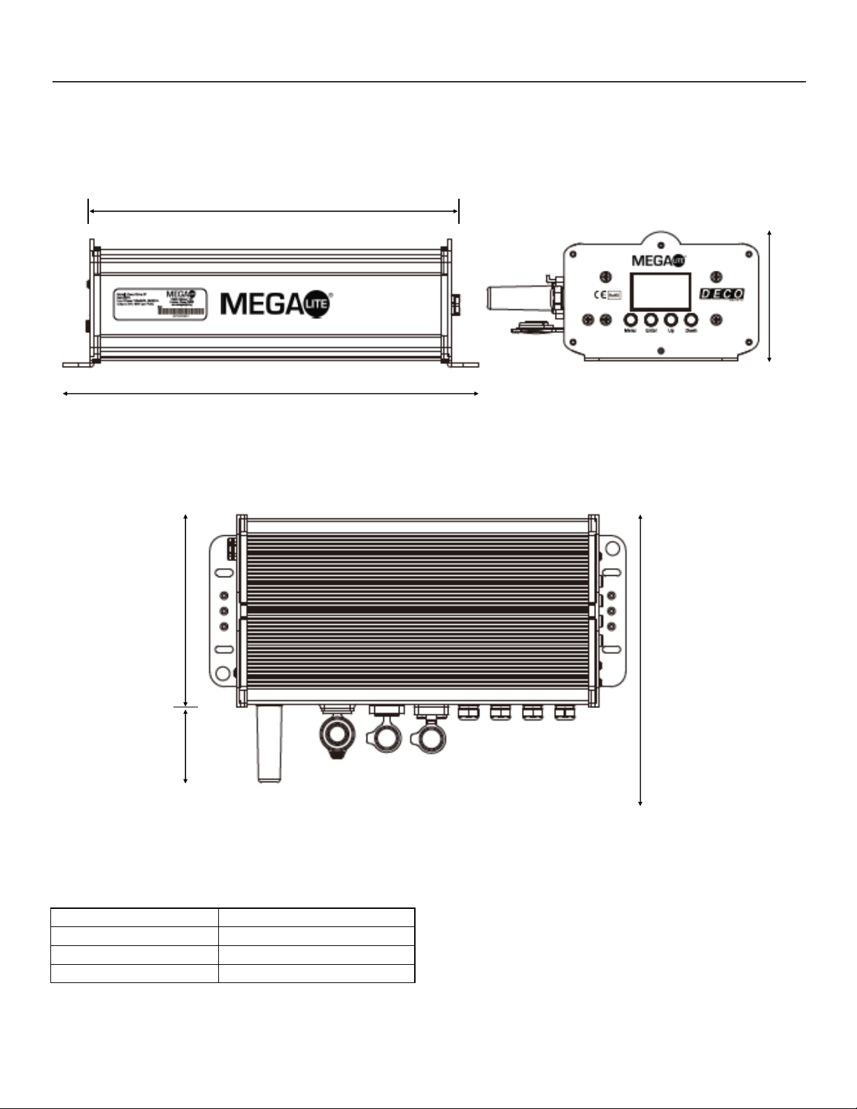
8
Size & Weight
Fixture Size 13.25" X 8.5" X 4.12"
Fixture Packaged 14.75" X 12" X 6.75"
Net Weight 8.8lb
Gross Weight 9.8lb
13.25”
4.12”
6”
9.5” (With Power Cable)
2.5”
11.87”
Cleaning and Maintenance
Installation Maintenance: The operator has to make sure that the unit is operating safely and has the installations and
electronics checked by an expert every 2 years.
The following points have to be considered during the inspection:
1) All screws used for installing the device or part of the device have to be tightly connected and must not be corroded.
2) There must not be any deformations on the housing, fixation and installation spots (rack, suspension, trussing).
3) The electronic power supply cables must not show any damages, material fatigue (e.g. porous cables) or sediments.
Further instructions depending on the installation spot and usage have to be adhered by a skilled installer and any
safety problems have to be removed.
4) Cooling fins must be clear of any debris.
9
Rigging the Fixture
Caution!
1. The installation must be carried out by an authorized dealer or trained professional.
2. Unit may cause severe injures if you have doubts concerning the safety do not install.
3. Unit is to be 24inches away from flammable materials (decoration material)
4. Installation location must have adequate air flow.
5. M10 treaded mount is provided on the side of the fixture for clamp mount
When rigging a unit it is very important that you follow common safety procedures. Rigging requires extensive experi-
ence including but not limited to calculating working loads, material being used and periodic safety inspections. If you
lack these qualifications, do not attempt the installation yourself, instead use a professional structural rigger.
When rigging the unit always be secured with a secondary safety attachment. The installation location of the Fixture has
got to be built in the way that it can hold 10 times the weight for 1 hour without any failures. Installation should be
checked at least one time a year by a skilled person.
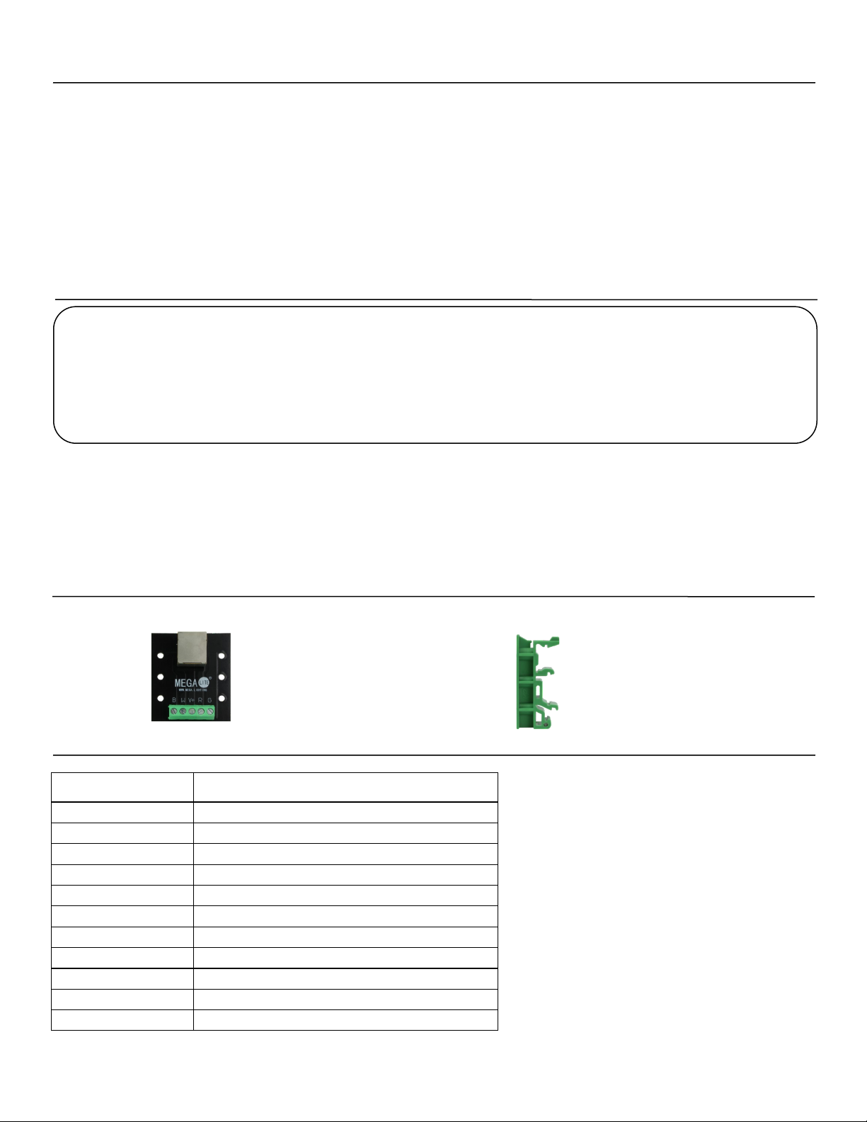
Parts List
Accessories
Item Number Descripon
5070-ANT IP RATED ANTENA
5074-FAN FAN
5074-HOU-CEN CENTER HOUSING EXTRUSION
5074-HOU-DIS DISPLAY SIDE HOUSING
5074-HOU-MOU MOUNTING SIDE HOUSING
5074-PCB-DIS DISPLAY PCB
5074-PCB-DRI DRIVER PCB
5074-PCB-WIR WIRELESS DMX PCB A40895 WDMX
CON-COL-DC5 IP 67 5 POLE PARALLEL CONNECTOR
5060-DIN DIN RAIL MOUNTS
5060-ADA 5PIN SCREW TERMINAL TO RJ45 ADAPTER
5060-DIN (din rail mount)5060-ADA (not intended for outdoor use)
10
Mega Lite
18668 Highway 16N
Helotes, Texas 78023
Ph 210-684-2600 Fax 210-855-6279
www.mega.lighting / info@mega.lighting
Customer Support
Mega Lite has a customer support line to provide set up help and to answer any question should you encounter a prob-
lem. Please visit our website for any other related technical documents. For service related issue please contact our
service dept.
Monday—Friday 9am to 6pm CST
Voice: 210-684-2600
E-mail: service@mega.lighting
Document
Version Date Fixture Software Notes
1.0 09/01/2022 V1.1
Manual Version
Please Visit www.mega.lighting for the most up to date manual version
Table of contents
Other MegaLite DC Drive manuals


Popular DC Drive manuals by other brands


Danfoss
Danfoss vlt fcd 302 operating guide

Danfoss
Danfoss VLT HVAC Basic Drive FC 101 quick guide

Spid Elektronik
Spid Elektronik MD-01 manual

Siemens
Siemens SINAMICS SM150 6SL3810-7NN38-0AA1 Operating and installation instructions

Inovance
Inovance CP700 Series user guide

Reliance electric
Reliance electric MinPak Plus instruction manual