Acuity Brands eldoLED POWERdrive 50U-M4Z0X Guide
July 30, 2020
POWERdrive 50W DESIGN GUIDE

POWERdrive 50W DESIGN GUIDE –July 30, 2020
Page 2/19
CONTENTS
1. Introduction...........................................................................................................................................................................3
2. Electrical Design.....................................................................................................................................................................3
Output Characteristics.......................................................................................................................................................3
Electrical Connections .......................................................................................................................................................4
LED load configurations.....................................................................................................................................................5
Meeting Title 24/JA8 startup.............................................................................................................................................7
3. DMX wiring ............................................................................................................................................................................7
Remote mounting..............................................................................................................................................................7
Creating DMX IN and DMX OUT connections for the luminaire........................................................................................8
DMX Wire type ..................................................................................................................................................................9
Grounding........................................................................................................................................................................10
DMX Input isolation.........................................................................................................................................................10
4. Driver protections................................................................................................................................................................10
5. Mechanical installation........................................................................................................................................................11
Driver Lifetime .................................................................................................................................................................11
Sound...............................................................................................................................................................................12
Grounding........................................................................................................................................................................12
6. Driver configuration.............................................................................................................................................................12
Startup and Fail mode .....................................................................................................................................................12
Group Scaling...................................................................................................................................................................13
Interpolation....................................................................................................................................................................13
NTC throttling temperature.............................................................................................................................................14
Power Scaling...................................................................................................................................................................14
DMX network settings .....................................................................................................................................................15
RDM Settings ...................................................................................................................................................................17
7. Best Practices.......................................................................................................................................................................17
Troubleshooting ......................................................................................................................................................................18
References...............................................................................................................................................................................19
Disclaimer ................................................................................................................................................................................19
POWERdrive 50W DESIGN GUIDE

POWERdrive 50W DESIGN GUIDE –July 30, 2020
Page 3/19
1. Introduction
Thank you for your interest in the eldoLED POWERdrive 50W DMX LED driver family. This design guide addresses common
design features, configurations, and performance considerations when designing a luminaire incorporating any one of the
following POWERdrive LED drivers
*
:
-POWERdrive 50U-M4Z0X
-POWERdrive 50S-M4Z0X (scheduled for release in a few weeks)
-POWERdrive 50SA-M4Z0X (scheduled for release in a few weeks)
2. Electrical Design
Output Characteristics
A POWERdrive LED driver contains four constant-current LED outputs, that are specifically designed to power LED light
engines. It is not recommended to use a POWERdrive LED driver to power other electronic loads or circuitry; this may
cause unpredictable behavior and/or damage to the POWER LED driver.
Each LED output can support an LED load with a forward voltage up to 55V. The nominal output current for each LED
output can be programmed in 1mA steps between 150mA and 1400mA. Consult the product datasheet for detailed
information on the acceptable operating window of the driver.
The cumulative output power of a POWERdrive LED driver across all four LED outputs cannot exceed 50W. This power
does not have to be evenly distributed, i.e. each LED output can support a different forward voltage and forward current.
The LED outputs of a POWERdrive LED driver can be programmed to be controlled independently, grouped, or disabled.
Between 1 and 4 DMX addresses will be visible to the DMX network based on the programming of the driver. See the
Driver Configuration section for more detailed information.
The POWERdrive LED driver is designed to meet UL Class 2 requirements. This means that each LED output meets these
requirements:
-Output voltage less than 60V
-Output current less than 5A
-Output power less than 100VA
*
The wiring diagrams in this Design Guide show the physical connector layout for POWERdrive 50U-M4Z0X. Nevertheless, the wiring
guidelines in this Design Guide apply to all the POWERdrive LED driver configurations listed here.
POWERdrive 50W DESIGN GUIDE –July 30, 2020
Page 4/19
Electrical Connections
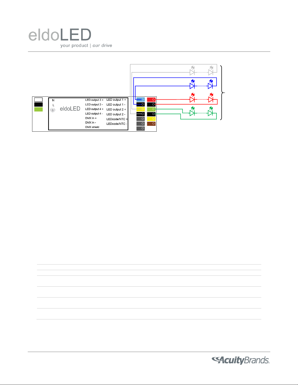
A POWERdrive LED driver has 16 color-coded connectors (3 for mains, 8 for LED outputs, 3 for DMX, and 2 for LEDcode /
NTC), see Figure 1. Each LED load must have a dedicated (+) and (-) connection to the POWERdrive LED driver. To facilitate
wiring, the LED output (+) connectors are color-coded, with Red, Red, Green, Blue, and Yellow corresponding to LED
outputs 1, 2, 3, and 4, respectively.
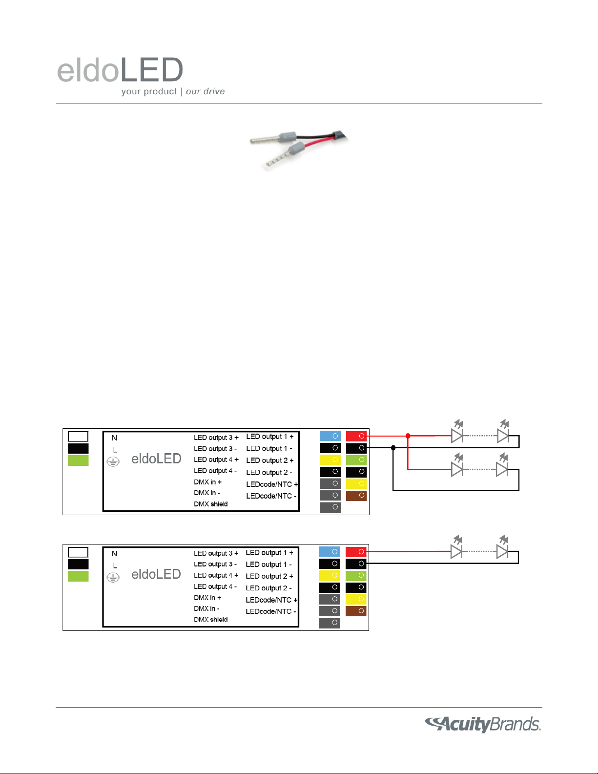
The acceptable wire cross section for each connection type is listed in Table 1. Wire sizes outside this range may damage
the connector pole or prevent the wire from making a secure mechanical and/or electrical connection. Smaller wire sizes
can be accommodated in combination with a ferrule, see Figure 2. Insertion of multiple loose wires into a driver terminal
may result in unacceptable mechanical or electrical contact to both wires. Instead, consider using a twin cable ferrule to
connect multiple small wires (e.g. DMX wiring) together for insertion into a connector pole.
POWERdrive
DMX
4 LED group
(4 control channels)
Figure 1: A POWERdrive LED driver has 16 color-coded connector poles. Each LED load must have a dedicated (+) and (-)
connection to the POWERdrive LED driver. The 4 LED outputs that can be programmed to be controlled
independently, grouped, or disabled.
Table 1: Acceptable wire cross section for the various connection types to a POWERdrive LED driver. Note that the
acceptable wire cross section for LED output and LEDcode/NTC are restricted for POWERdrive 50SA-M4Z0X drivers so
the plastic endcap can exert enough clamping force onto the mains cabling.
POWERdrive 50U-M4Z0X
POWERdrive 50S-M4Z0X
POWERdrive 50SA-M4Z0X
Mains power
AWG 20-16
0.5-1.5mm²
AWG 20-16
0.5-1.5mm²
AWG 20-16
0.5-1.5mm²
LED output
AWG 20-16
0.5-1.5mm²
AWG 20-16
0.5-1.5mm²
AWG 20-18
0.5-0.75mm²
LEDcode / NTC
AWG 20-16
0.5-1.5mm²
AWG 20-16
0.5-1.5mm²
AWG 20-18
0.5-0.75mm²
DMX
AWG 24-16
0.2-1.5mm²
AWG 24-16
0.2-1.5mm²
AWG 24-16
0.2-1.5mm²
POWERdrive 50W DESIGN GUIDE –July 30, 2020
Page 5/19
LED load configurations
Each LED output of the POWERdrive LED driver is powered by a separate current source to enable independent control of
each LED output, regardless of the LED load that is connected. However, this flexibility does impose constraints on how
LED light engines can be connected to the LED outputs. Figure 3 shows the acceptable LED load configurations for a
POWERdrive LED driver. Multiple LED light engines can be connected either in series or in parallel if the total LED load (in
terms of cumulative forward voltage and output current) does not fall outside the operating window for each LED output,
as specified in the product datasheet. Any series/parallel connection of LED loads shall be designed considering the
variations in forward voltage and/or current over the full operating range of the luminaire. Figure 4 shows LED load
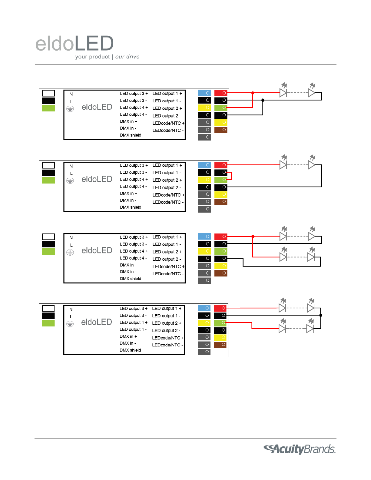
configurations that are not acceptable for a POWERdrive LED driver. In particular:
-multiple LED outputs cannot be connected in series to power an LED load with a forward voltage > 55V
-multiple LED outputs cannot be connected in parallel to deliver a drive current that exceeds the maximum drive
current that can be delivered by a single LED output
-common-anode or common-cathode configurations are not acceptable.
Cross connecting multiple LED outputs of a POWERdrive LED driver may result in permanent damage to the LED driver
itself and/or the LED light engine(s).
Figure 2: Smaller wire sizes can be accommodated in combination with a ferrule.
POWERdrive
DMX
✓Multiple LED light engines can be connected in parallel to a single LED output
POWERdrive
DMX
✓Multiple LED light engines can be connected in series if the total string voltage remains < 55V
Figure 3: These LED load configurations are acceptable.
POWERdrive 50W DESIGN GUIDE –July 30, 2020
Page 6/19
POWERdrive
DMX
Multiple driver LED outputs cannot be connected in parallel to increase the total drive current through an LED load.
POWERdrive
DMX
Multiple driver LED outputs cannot be connected in series to support an LED load with a forward voltage > 55V.
POWERdrive
DMX
Multiple LED light engines cannot have separate cathodes but share a common anode.
POWERdrive
DMX
Multiple LED light engines cannot have separate anodes but share a common cathode.
Figure 4: These LED output configurations are not acceptable and may result in permanent damage to the POWERdrive
LED driver and/or the LED light engine(s).

POWERdrive 50W DESIGN GUIDE –July 30, 2020
Page 7/19
Meeting Title 24/JA8 startup
The POWERdrive LED driver can meet the startup time requirements as specified in California Title 24/JA8 out of the box,
i.e. there is no need to order a “special” configuration. However, this does require the test setup to meet certain
conditions.
Per the DMX512A standard, a POWERdrive LED driver will wait 1250ms after cold start for a valid DMX control signal to be
presented on the input. If no DMX input is received within 1250ms after cold start, the POWERdrive LED driver will follow
the behavior configured in the Startup Mode settings. If a POWERdrive LED driver detects a live DMX network after cold
start, it will respond to any non-zero DMX setpoint commands within 500ms.
To achieve first-light within 500ms after cold start, the test setup must meet these conditions prior to executing the test:
-the POWERdrive LED driver is connected to a DMX network
-the DMX network is up and running
-the DMX network continuously sends out valid, non-zero setpoint commands to the POWERdrive LED driver
3. DMX wiring
Remote mounting
POWERdrive LED drivers are suitable for remote lighting applications, i.e. applications where the LED driver is not
mounted in or near the luminaire that is powered by the LED driver. From a functional point of view, though, the distance
between a POWERdrive LED driver and the LED light engine(s) should not exceed 100m (384ft).
One key consideration in a remote lighting application is the voltage drop in the cable(s) between the LED driver and the
LED light engine(s). The total load on each LED output (i.e. the sum of the forward voltage of the light engine and the
voltage drop in the cable between driver and light engine), shall not exceed the maximum allowable output voltage of the
POWERdrive LED driver under all expected operating conditions (i.e. low temperature, maximum current, LED binning
variations, etc.).
A large voltage drop in the cabling between a POWERdrive LED driver and LED light engine yields more power loss in the
cabling and reduces the efficiency of the overall luminaire system. When trading off wire cross section and voltage drop in
the cabling, keep in mind that the POWERdrive LED driver only accept wires with certain cross sections, see Table 1. A
good rule of thumb is to limit the voltage drop between an LED driver and the LED load to about 1V.
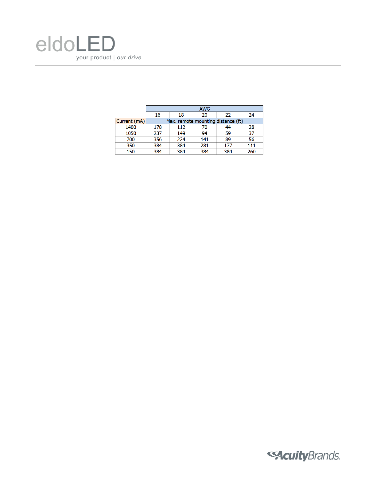
Table 2 lists the typical remote mounting distance (ft) that can be supported with various combinations of current and
wire size. The distance is based on the voltage drop being less than 1V.
POWERdrive 50W DESIGN GUIDE –July 30, 2020
Page 8/19
It is, in general, best to keep the remote mounting distance as short as possible. Depending on the site and application
requirements in terms of EMI/RFI emissions and susceptibility, one may consider running remote wiring in conduit or
using shielded cables. It is the responsibility of the fixture OEM to validate the design and performance of the fixture
system in the application, including remote-mounted LED driver solutions.
Creating DMX IN and DMX OUT connections for the luminaire
Each POWERdrive LED driver represents one “unit load”on the DMX bus. The DMX standard allows up to 32 “unit loads”
on each bus. If additional drivers are needed on the bus, then a repeater or signal booster is necessary.
DMX utilizes daisy-chain connections between devices on a DMX network. To ensure trouble-free operation, close
attention must be paid to the DMX wiring within a luminaire as well as in the DMX network itself. To facilitate daisy-
chaining of multiple DMX luminaires in a DMX network, each DMX luminaire should provide separate DMX IN and DMX
OUT connections, each containing DMX +, DMX - and DMX SHIELD conductors (all three are required for proper
operation). This can, for example, be accomplished as shown in Figure 5 and . A “T-tap” connection to the DMX terminals
of the POWERdrive LED driver within the luminaire should be made as short as possible, preferably less than 2 -3 inches.
Care must be taken when preparing the DMX cable; the shield/drain wire should not make any contact to any part of the
fixture other than the DMX shield input terminal on the driver. Accidental contact with the fixture body (earth ground)
may result in interference with the DMX signal.
Table 2: Maximum allowable cable distance (in ft) as function of the wire gauge and drive current that keeps the
voltage drop in the cable below 1V.

POWERdrive 50W DESIGN GUIDE –July 30, 2020
Page 9/19
DMX Wire type
The DMX protocol operates over an RS-485 physical layer at 250kbaud. To comply with the standard, cabling with specific
operating characteristics must be used to support this fast, digital signal.
DMX-compliant cables should be used for both the input and output connections to a luminaire. If multiple DMX LED
drivers are used within the same luminaire, DMX-compliant cables should be used between the LED drivers. Best practice
is to provide as much separation as possible between power wires (mains or LED outputs) and DMX signal wires within the
luminaire.
Check the DMX512-A standard for the technical requirements on DMX cabling. In general, a DMX cable contains a twisted
pair with a low capacitance and a nominal characteristic impedance of 120Ω; the cable can be shielded or unshielded. An
example of a DMX-compliant cable is Belden 9841. A category 5 or above network cable is also compliant.
Figure 5: Proper wiring of a DMX fixture is critical to trouble-free operation. To facilitate daisy-chaining of multiple
luminaires in a DMX network, each luminaire should provide separate DMX IN and DMX OUT connections. This can be
accomplished as shown here. The “T-tap” connection to the DMX IN terminals of a POWERdrive LED driver within the
luminaire should be made as short as possible, preferably less than 2 -3 inches.

POWERdrive 50W DESIGN GUIDE –July 30, 2020
Page 10/19
Grounding
Depending on the type of DMX-compliant cable that is used, the DMX shield conductor may be separate from the cable
shield/drain wire. The DMX Shield should only connect to earth ground at the DMX controller. Inside the fixture, the DMX
Shield should only connect to the DMX Shield terminal on the driver. Termination of the DMX cable inside the luminaire
must ensure that the DMX Shield does not come into electrical contact with the fixture body.
DMX Input isolation
The DMX control interface is electrically isolated from the Class 2 LED outputs and mains input. This improves the
robustness of the POWERdrive LED driver against surge events and accidental mis-wiring.
4. Driver protections
The POWERdrive 50W driver has several protection mechanisms to comply with certification standards (e.g. UL Class 2
LED outputs) and to prevent damage to the driver during operation. These protection mechanisms include:
Thermal protection –When the internal LED driver temperature exceeds a factory preset limit, the output
current on all LED outputs is gracefully scaled back until the LED driver temperature drops below this limit. If the
internal LED driver temperature continues to increase, despite a decrease in output current, the LED driver
eventually shuts down when a second temperature threshold is reached. Once the temperature drops below the
threshold, the driver will restart.
Open protection –All LED outputs are turned off whenever the LED driver detects an open circuit on any one of
the LED outputs. The LED driver will automatically attempt a restart every 400ms after an open circuit is
detected.
Ceiling
Pendant
Fixture
DMX +
DMX -
DMX SHIELD
Single cable down stem
Shared DMX
shield/drain conductor
Junction Box
DMX IN DMX OUT
Figure 6: This example shows how a cable with two twisted conductor pairs can be used to bring a DMX signal to a
pendant luminaire, while still minimizing the length of the T tap.

POWERdrive 50W DESIGN GUIDE –July 30, 2020
Page 11/19
Short protection –All LED outputs are turned off whenever the LED driver detects a short circuit on any one of
the LED outputs. The LED driver will automatically attempt a restart every 400ms after a short-circuit is detected.
Overload protection –The driver monitors the cumulative load across all LED outputs. Whenever this cumulative
load exceeds the maximum output power rating of the LED driver, the output current on all LED outputs is
gracefully scaled down until the cumulative load drops below the maximum output power rating of the LED
driver.
Reverse polarity –The LED driver does not yield any current if the polarity of the load on the LED output is
reversed. This situation will not damage the LED driver but may damage the LED load due to the reverse voltage
across the LEDs.
These protection mechanisms typically kick in if one or more of these limits are violated:
-The current of any LED output exceeds 1400mA
-The cumulative current for all LED outputs exceeds 3400mA
-The LED load on any LED output exceeds 55V
-The total output power of the driver exceeds 50W
-The internal LED driver temperature exceeds a factory preset limit
The first limit is pro-actively enforced during programming of a POWERdrive LED driver in FluxTool, i.e. the nominal
current for any one LED output cannot be programmed above 1400mA. The other limits cannot be enforced when
programming a POWERdrive LED driver since these are dependent on factors that are beyond eldoLED’s control, including:
-the operating conditions in the final application
-the LED loads that are connected
-the number of LED outputs that are on
For example, the nominal current for each LED output can be programmed to, say, 1000mA, resulting in a cumulative
programmed current of 4000mA. This situation is acceptable if the DMX controller ensures that at most 3 LED outputs are
at 100% at any one time, resulting in an effective cumulative current of only 3000mA. Now, let’s further assume that the
maximum LED forward voltage on each LED output is 25V. The total output power now becomes the critical limit, i.e. at
most 2 LED outputs can be on at 100% at any one time.
It is the responsibility of the luminaire design engineer to ensure none of the limits above are violated in the targeted
application, including worst-case operating conditions such as cold start-up.
5. Mechanical installation
Driver Lifetime
eldoLED drivers are designed to operate reliably if the case temperature (Tc max) of the driver does not exceed the
maximum allowable case temperature as specified in the product datasheet. The driver case temperature to meet a
lifetime of 50k hours is also specified in the product datasheet. The fixture design must guarantee that the Tc point stays
below its maximum value under all operating conditions of the luminaire.
POWERdrive 50W DESIGN GUIDE –July 30, 2020
Page 12/19
Sound
eldoLED drivers are designed and tested to meet Class A (<24dBA @1m) sound pressure levels under steady state
operating conditions. When mounting the POWER LED driver, consideration should be given to the luminaire system and
how it may amplify or attenuate any vibrations from the LED driver into the application space.
Grounding
A POWERdrive LED driver must be grounded for proper EMC and safety performance. Each POWERdrive LED driver
includes an earth ground connection. Best practice is to also ground the POWERdrive LED driver housing by mounting it to
the luminaire body in the event the earth ground connection is interrupted. A star washer under the head of the
mounting screw is often adequate; the teeth of the washer penetrate the painted surface and create a good electrical
connection between the LED driver housing and the luminaire body.
6. Driver configuration
The POWERdrive LED driver is a fully programmable digital LED driver that is designed to support high-speed multi-
channel (color) lighting applications. In addition to traditional LED driver settings (e.g. drive current, minimum dimming
level, dimming curve), the POWERdrive LED driver includes a variety of (user) configurable parameters that enable more
advanced functionality. Some of these parameters are directly accessible through FluxTool, while others can only be set in
the eldoLED factory.
The order number configurator in the product datasheet of a POWERdrive LED driver only captures the most common
driver settings and configurations. This section explains the more advanced configuration settings. Please contact your
eldoLED Sales representative if you need one or more of these settings to be programmed in the driver out of the factory.
Startup and Fail mode
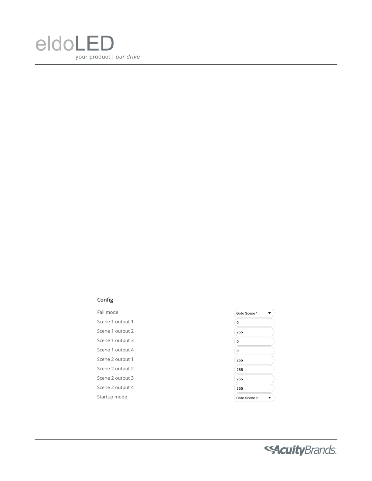
The behavior of a POWERdrive LED driver, in the absence of a DMX signal, can be fully configured in the Config section of
the FluxTool software, see Figure 7.
Figure 7: The behavior of a POWERdrive LED driver, in the absence of a DMX signal, can be configured in the Config
section of FluxTool.
POWERdrive 50W DESIGN GUIDE –July 30, 2020
Page 13/19
By default, a POWERdrive LED driver retains its last value when the DMX signal is lost and sets all LED outputs to 20% in
the absence of a DMX control signal after cold start. To overwrite this behavior, the user must first define 1 or 2 unique
static scenes. A scene has 4 output entries corresponding to the intensity level for each LED output of the POWERdrive
LED driver. Each intensity level can be set in the range 0 –255, corresponding to 0 –100% of the nominal drive current.
Fail mode and Startup mode are then tied to one of the two scenes via a pull-down menu in the Config section. Note that
Fail mode can also be set to “retain”, i.e. the driver will then retain the last intensity levels for all LED outputs whenever
the DMX signal is lost during normal operation. In the example of Figure 7, all outputs go to 100% after cold start (in the
absence of a DMX signal) but only the second LED output goes to 100% when the DMX signal is lost during normal
operation. Changes to the DMX startup/fail mode, which are programmed into a POWERdrive LED driver via FluxTool, may
only take effect after mains power to the POWERdrive LED driver is interrupted for at least 3 seconds.
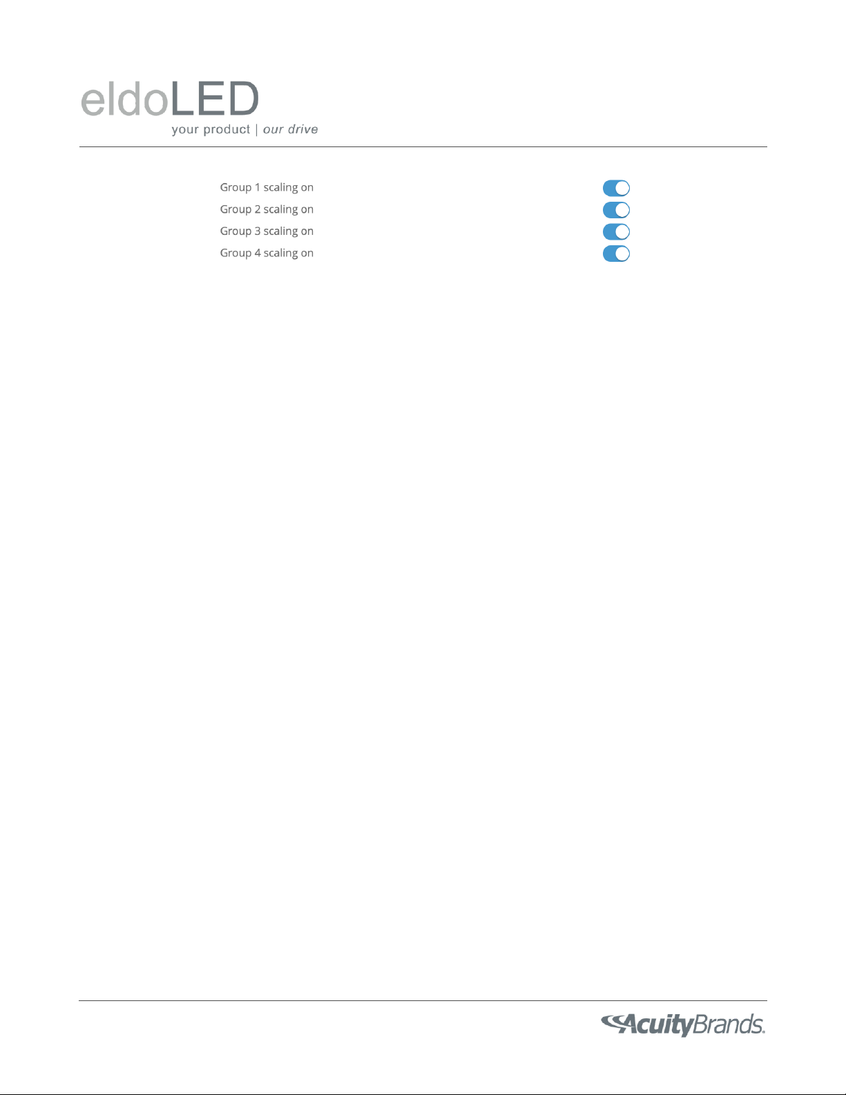
Group Scaling
A POWERdrive LED driver has 4 LED outputs. By default, all LED outputs are “active”when the POWERdrive LED driver is
powered, i.e. the driver will try to deliver the programmed current to each LED output. LED outputs can be set to “active”
or “inactive”via the Group Scaling settings in the Control section of FluxTool, see Figure 8.
In a variety of luminaire applications (e.g. direct-color RGB) only a subset of LED outputs is connected to an LED load. Best
practice is to set any LED output, which is not connected to an LED load, to “inactive”to ensure optimal LED driver
performance. The example in Figure 8 shows all LED outputs set to “active”in the Control section of FluxTool.
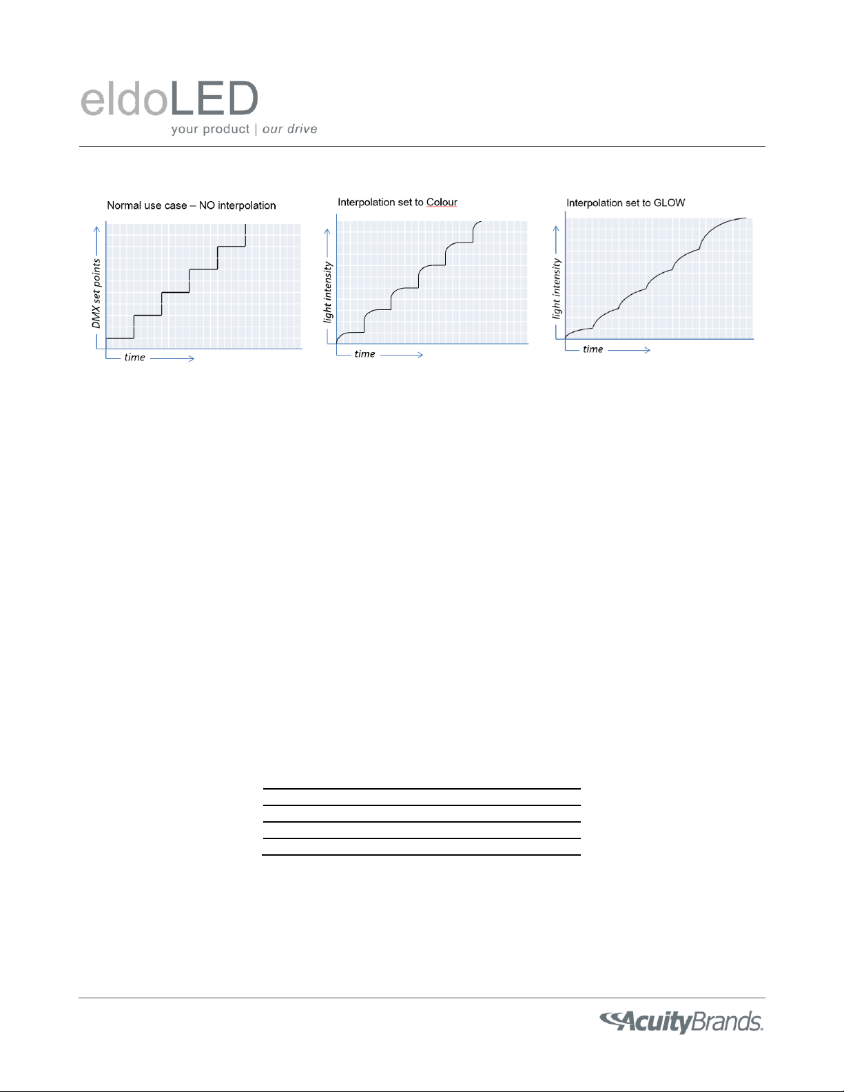
Interpolation
The POWERdrive LED driver supports several interpolation methods between setpoint changes:
-Off
-Video
-Colour
-White
-Glow
When interpolation is set to Off, no interpolation is used, i.e. the driver will respond immediately to setpoint changes. The
four remaining options enable increasingly higher levels of interpolation with Video offering the lowest level of
interpolation and Glow offering the highest level of interpolation. Higher levels of interpolation result in smoother fades
between setpoints at the expense of a slight delay in the time it takes to reach the setpoints. The default interpolation
setting for a POWERdrive LED driver is “Colour”. Figure 9 shows, conceptually, the difference between some of the
interpolation settings that are offered in a POWERdrive LED driver.
Figure 8: LED outputs can be set to “active”or “inactive”via the Group Scaling settings in the Control section of
FluxTool. Best practice is to set any LED output, which is not connected to an LED load, to “inactive”to ensure optimal
LED driver performance. In this example, all LED outputs are set to “active”.
POWERdrive 50W DESIGN GUIDE –July 30, 2020
Page 14/19
NTC throttling temperature
The POWERdrive LED driver can monitor the temperature of an external 47kΩNTC thermistor that is connected to the
LEDcode / NTC terminals. Whenever the NTC temperature exceeds the NTC throttling temperature specified in the Control
section of FluxTool, the output current to all LED outputs is immediately decreased to 25% of the actual current. For
example, by placing the NTC on the LED light engine, the POWERdrive LED driver can prevent overheating of the LED light
engine in case it gets accidentally disconnected from its heatsink.
The default NTC throttling temperature is 70 °C but is ignored when no NTC is connected to the LEDcode / NTC terminals.
Power Scaling
The POWERdrive LED driver includes an overpower protection circuit that prevents the LED driver from delivering more
power than its maximum output power rating. When triggered, the overpower protection circuit turns off the LED driver,
resulting in loss of light, which, in most lighting applications, is undesirable. Power Scaling offers a more graceful way to
limit / scale back the output power of a POWERdrive LED driver. Power Scaling is enabled via firmware in the POWERdrive
LED driver and can be configured in FluxTool.
To illustrate the concept of Power Scaling, consider a 50W POWERdrive LED driver that is connected to 4 LED loads, each
with a forward voltage of 50V. To prevent the overpower circuit from kicking in, the cumulative output current across all
LED outputs cannot exceed 1000mA. Assuming equal loading across all LED outputs, the maximum allowable drive current
per LED output, Ifmax, depends on the number of LED outputs that are on at any one time:
# LED outputs that are on
Ifmax
1
1000mA
2
500mA
3
333mA
4
250mA
The controller in a DMX network is typically not setup to enforce the absolute maximum output power for each LED
driver. Moreover, in most (full color) lighting applications it will be difficult to predict a-priori how many LED outputs will
be on at any one time. Consequently, the safest choice in the example above is to set the drive current for each LED
output to 250mA. However, this results in the LED driver being underutilized, i.e. the LED driver yields significantly less
power than what it is capable of delivering, which, in turn, may drive up the cost of an installation as more LED drivers
Figure 9: Examples of the available interpolation methods in a POWERdrive LED driver.

POWERdrive 50W DESIGN GUIDE –July 30, 2020
Page 15/19
may need to be specified. The preferred behavior in the example above is that the maximum output current per LED
output is gracefully scaled back as more LEDs are turned on, while still maintaining the proper drive current ratio between
the 4 LED outputs to ensure color accuracy. Power Scaling is designed to support this. With Power Scaling enabled, the
total power delivered by the POWERdrive LED driver can remain constant, regardless of how many LED outputs are on.
Furthermore, Power Scaling allows the POWERdrive LED driver to operate close to its maximum output power rating,
regardless of the number of LED outputs that are on.
Power Scaling is disabled when set to 0 (default), i.e. the POWERdrive LED driver will deliver on the incoming DMX
setpoints for all LED outputs, regardless whether the requested DMX setpoints result in an overpower situation. To enable
Power Scaling, enter an integer value in the range 1 –255 in FluxTool. Use this formula to calculate the appropriate value
for Power Scaling:
Power Scaling = 255 x Pmax LED driver / Pmax LED load (rounded to the nearest integer)
where
Pmax LED driver is the maximum output power of the POWERdrive LED driver
Pmax LED load is the worst-case LED load that the LED driver may experience
Going back to the example above, Pmax LED driver = 50W. Now, let’s further assume that the output current for each LED
output is programmed to 1000mA. The worst-case LED load that the LED driver could experience occurs when all 4 LED
outputs are on at full brightness, i.e. Pmax LED load = 4 x 1000mA x 50V = 200W. The appropriate Power Scaling value in this
example, per the formula above, is then 64. Whenever the sum of DMX setpoints for all four LED outputs exceeds the
Power Scaling value x N, where N is the total number of LED outputs that are active (see Figure 8), Power Scaling reduces
the output current to all LED outputs while maintaining the proper ratio between LED outputs. Continuing the example
above, if the DMX setpoint for LED output 1 is 255 while the DMX setpoint for the other three LED outputs is 0, Power
Scaling is not applied (255 + 0 + 0 + 0 < 64 x 4), i.e. the output current to LED output 1 is 1000mA. Now consider the
scenario where the DMX setpoint for LED output 2 is changed from 0 to 255. Since the sum of incoming DMX setpoints
now exceeds the maximum allowable sum (255 + 255 + 0 + 0 > 64 x 4), Power Scaling kicks in and reduces the current to
both LED outputs proportionally, i.e. LED outputs 1 and 2 now deliver each only 500mA. In both scenarios, the total power
delivered by the POWERdrive LED driver remains at 50W.
Note that the Power Scaling formula above is only suitable if all LED outputs have similar LED loads. For asymmetric load
conditions, please contact your eldoLED Sales representative for further assistance in calculating the appropriate Power
Scaling value.
DMX network settings
A POWERdrive LED driver has 4 LED outputs which, by default, are tied to separate, sequential DMX addresses, allowing
each LED output to be controlled independently. However, in some applications it may be desirable to tie multiple LED
outputs to the same DMX address, allowing multiple LED outputs to react in unison to a dimming command. The mapping
between DMX addresses and LED outputs can be fully configured in the section DMX network settings in FluxTool, see also
Figure 10:
Group x channel mapping with x in {1, 2, 3 4} –specifies to which DMX address (“channel”) each LED output
(“group”) is tied. 1 corresponds to the network start address specified. Valid values are between 1 and Network
channel count.

POWERdrive 50W DESIGN GUIDE –July 30, 2020
Page 16/19
Network channel count –this corresponds to the number of unique DMX channels that are used; this value
should equal the highest number that is used in the Group channel mapping fields. It is important that this value
is set correctly to ensure correct RDM discovery of the driver addresses. The default value is 4.
Network resolution –this value defines the dimming resolution that is used; it can be either 8-bit (default),
corresponding to 256 steps, or 16-bit, corresponding to 65536 steps. Note that the 16-bit option consumes two
DMX channels which form a “course”and “fine”control of the associated output.
Network start address –This is the first DMX address of the driver and the default value is 1. It is typically set via
RDM during the commissioning process. All the driver channel addresses, as defined by the network channel
count and channel mapping fields, are numbered relative to the start, or base, address. For example, if all the
channels have a channel mapping value of “1”, they are all controlled by the network start address. The outputs
that are mapped to “2”would be controlled by the DMX address corresponding to the network start address + 1.
Figure 10(a) reflects the scenario where each LED output is tied to a separate DMX address (Network channel count = 4);
Figure 10 (b) reflects the scenario where all LED outputs are tied to a single DMX address (Network channel count = 1);
Figure 11 demonstrates how channel mapping can be used to force specific DMX addresses in situations where only a
subset of LED outputs is used. Consider a luminaire family that includes multiple luminaire configurations, each with an
ambient light and downlight component. Depending on the desired light output, the ambient light component may
require up to two LED outputs while the downlight component only requires one LED output. From an assembly
perspective, it may be desirable to always wire the downlight LED light engine to LED output 3. Figure 11 (middle) shows
the network settings that map LED output 1 and 3 to the first and third DMX address, respectively, of the POWERdrive LED
driver. In this case, the driver consumes three DMX addresses on the network. To conserve DMX addresses, though, LED
output 3 can be mapped to DMX address 2, as shown in Figure 11 (right).
(a)
(b)
Figure 10: The section DMX network settings in FluxTool gives users full control over the network settings of the driver,
including the mapping between DMX channels and LED outputs, network channel count, and network resolution.
Picture (a) reflects the scenario where each LED output is tied to a separate DMX address; picture (b) reflects the
scenario where all LED outputs are tied to a single DMX address.

POWERdrive 50W DESIGN GUIDE –July 30, 2020
Page 17/19
RDM Settings
Most RDM settings are not configurable in FluxTool and must be programmed into the driver in the factory. POWERdrive
LED drivers ship with these default RDM settings:
-UID –This is a 12-digit hexadecimal number that is unique to each POWERdrive LED driver. Like a MAC address or
IP address, the UID ensures that messages can be sent to a specific POWERdrive LED driver. The UID itself is a
concatenation of these numbers:
oManufacturer ID –a 4-digit hexadecimal number that is unique to a manufacturer. The default
manufacturer ID in a POWERdrive LED driver is 0x646F (“eldoLED B.V.”)
oOEM ID –an eldoLED-assigned 2-digit hexadecimal sub-number. The default value is 0x00
oRange value - a 6-digit hexadecimal number that is uniquely assigned by eldoLED to each individual
POWERdrive LED driver
-Device Model Description –17 alphanumeric characters (A-Z+a-z+0-9, case-sensitive); default value is “LED
driver”
-Device Model ID –a 4-digit hexadecimal number that is hard-coded to 0x0101 for POWERdrive LED drivers
Please contact your eldoLED Sales representative if custom RDM settings for a POWERdrive LED driver is required.
7. Best Practices
To reduce the likelihood of issues in the field, it is best to communicate clearly how a DMX luminaire is configured to the
specifier, control system designer, installer, and commissioning party. The following information is, preferably, included in
the luminaire specification sheet and/or installation sheet:
-Default DMX address. Fixtures are typically not shipped pre-addressed; fixture addressing is done by the installer
or a commissioning contractor via RDM
-DMX channel count (footprint) of the fixture
(a)
(b)
(c)
Figure 11: In this example, LED outputs 2 and 4 are disabled via the group scaling command (a). Even though the driver
has only 2 active LED outputs, it may still be desirable to maintain the logical DMX address sequence for LED outputs 1
and 3. This is accomplished in the Network settings (b) by exposing only 3 addresses (Network channel count = 3) and
mapping LED output 1 and 3 to DMX address 1 (= Network start address) and 3 (= Network start address + 2),
respectively. If it is important, though, to conserve the number of DMX addresses that is consumed by the
POWERdrive LED driver, the Network channel count (c) can be set to 2. LED outputs 1 and 3 are then mapped in the
Network settings to DMX address 1 (= Network Start Address) and 2 (= Network Start Address + 1), respectively.
POWERdrive 50W DESIGN GUIDE –July 30, 2020
Page 18/19
-What function each channel controls (i.e. downlight, uplight, red, etc.)
-Default dimming curve of the driver
-RDM compatibility
-# of unit loads per fixture (typ. 1 per eldoLED driver)
-DMX run termination
oProvided by others/installer?
oProvided in the fixture?
-DMX connection type (wire colors, connector types, etc.)
oPigtail, RJ45, XLR, others?
oMapping between wire color and function
-Default power-on operation without DMX input (i.e. full on, off, 50%)
-DMX fault mode (i.e. maintain current setting, full on, off, etc.)
-Wiring diagram
-Tunable White/ Dim-to-warm: does the controller need to ensure that total power rating of the fixture is not
surpassed or is protection inherent in the driver configuration?
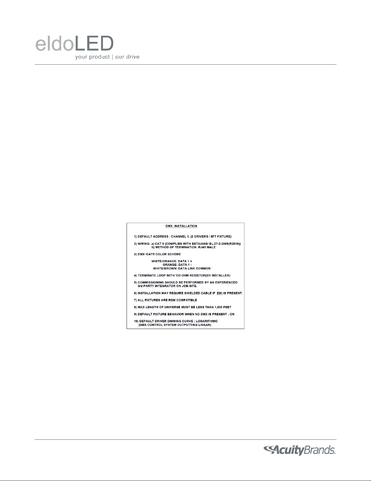
Figure 12 shows an example of notes that are affixed to a luminaire or installation sheet to communicate the relevant
DMX configuration to the installers.
Troubleshooting
If you don’t already have a handheld DMX/RDM device for troubleshooting, we recommend that you get one. These are
indispensable for testing, validating, and troubleshooting a DMX luminaire during development and in the field.
The process of troubleshooting a DMX driver is similar to that used when troubleshooting a complete DMX system.
1. Isolate the driver/fixture from the network.
Figure 12: Example of Installation notes

POWERdrive 50W DESIGN GUIDE –July 30, 2020
Page 19/19
2. Validate the function of the driver/fixture.
3. Validate the DMX network.
To validate the function of the driver, use the following steps:
1. Isolate the driver from the DMX network. Keep the LED load connected to the driver. Power the driver.
2. Validate the correct settings are programmed into the POWERdrive using the TOOLbox Pro interface and
FLUXtool software. Important items to verify are:
a. Group scaling is ON for outputs being used.
b. Network start address (usually corresponds to the first output).
c. Network channel count is equal to the number of outputs being used.
d. Channel mapping is valid for each output used.
3. Connect a portable DMX/RDM device to the DMX input of the driver. Make sure to use all three connections and
the correct polarity.
a. Verify that the driver outputs respond to DMX levels sent to the corresponding DMX addresses.
b. Verify that you can discover and identify the driver via RDM.
c. If (a) and (b) are successful, you have validated that the driver is functioning properly.
If the driver does not respond properly to DMX input in step #3, then:
4. Isolate the driver from the LED load. Test the LED load to verify that it operates properly.
5. Verify the load is connected properly to the driver.
a. Correct polarity
b. no cross-connected/shared outputs
c. forward voltage below 55V.
6. Retry step #3.
If the driver is still not responding, replace the driver with another unit and retest.
If these steps do not identify the issue, consult the eldoLED Driver Troubleshooting Guidelines document for more
comprehensive troubleshooting information.
References
Bennett, A. (2008). Recommended practice for DMX512: A guide for users and installers: Incorporating USITT DMX512-A
and remote device management, RDM. Eastbourne, UK: PLASA.
Disclaimer
The information in this guide is provided “as is” without warranty of any kind. Information in this document has been
compiled from many sources and is believed to be accurate, however, no liability is assumed for any loss or damage caused by
the use or misuse of any of the information contained herein. It is provided as a reference for the OEM in designing their
luminaire using eldoLED DMX drivers. It is the responsibility of the fixture manufacturer to understand the relevant
standards and test and validate the design and operation of their fixture system under anticipated application conditions.
This manual suits for next models
2
Table of contents
Popular DC Drive manuals by other brands


Siemens
Siemens SINAMICS SL150 operating instructions

Mitsubishi Electric
Mitsubishi Electric FR-D720-0.2K-G instruction manual

Becker
Becker L50/17 C SEF I1 Assembly and operating instructions

GFA
GFA ELEKTROMAT SI 25.15-30,00 GA25HC/15GD installation instructions

Siemens
Siemens simovert masterdrives manual

INVT
INVT Goodrive20-EU VFD Series Operation manual