Megaman JSJSLW420 User manual

lightwaveRF
Connect Series
Dimmer Switch (2 Gang)
Model No. JSJSLW420
Instruction Manual
www.megamanuk/lightwaverf.com


Get Started
What do I need?
How do I get started?
If the Dimmer has already been installed, refer to
the quick setup guide on the following pages to
get going. If you are planning to install the
Dimmer, please refer to the installation instruc-
tions that follow quick setup. This will guide you
through the installation process.
Help Video
You can scan this QR code with your
smartphone. It will take you to a video that will
help guide you through setup and installation.
To install the Dimmer, you will need to remove
and replace the existing lightswitch. This is
usually straightforward, but you must ensure that
there is a suitably deep housing (backbox) and
understand how to safely turn o the electricity
supply. You will also need suitable electrical
screwdrivers.

IMPORTANT: Please retain these instructions for guidance on how to link
Remote Handsets and other LightwaveRF Controllers. For additional
guidance please visit www.megamanuk.com/lightwaverf
Amber LED.
When illuminated,
Dimmer is o.
‘On’ Button.
Hold to raise light
level.
‘O’ Button.
Hold to lower light
level.
Blue LED. When
illuminated,
Dimmer is on.
Overview
Quick Setup Guide

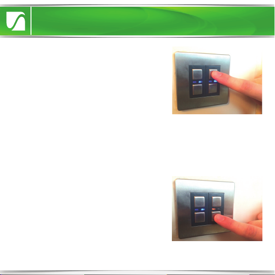
• Tap either ‘on’ (top) button once to
switch the Dimmer on (Blue LED
indicator will illuminate). Press and hold
the on button to raise the light level.
• Tap either ‘o’ (bottom) button once
to switch the Dimmer o (Amber LED
indicator will illuminate). Press and hold
to lower the light level.
Quick Setup
Manual Dimming
Linking the Dimmer to a
LightwaveRF Controller
1. On either gang press and hold down
both the ‘on’ and ‘o’ buttons until the
blue and amber LEDs flash alternately
then release them. The Dimmer Switch
is now in linking mode.
Quick Setup Guide

Dimming with a LightwaveRF
Controller or Smartphone
• Press the ‘on’ button on the Control-
ler (or smartphone app) once to switch
the Dimmer on (Blue LED indicator will
illuminate). Press and hold the on
button to raise the light level (on the
smartphone app use the slider).
Quick Start Guide
2. Using a LightwaveRF Controller or
smartphone app, press the button
intended to be linked; the blue light on
the Dimmer Switch will flash to
confirm that the remote is now linked.
• Press the ‘o’ button on the Control-
ler to switch the Dimmer o (Amber
LED indicator will illuminate). Press
and hold to lower the light level (on the
smartphone app use the slider).
Quick Setup Guide

NOTE: it is important to install this product in accordance with the following
instructions. Failure to do so may void your warranty.
LightwaveRF is fully legal to install in your own home. However, if in doubt,
always consult a qualified electrician.
Installation
Switched live
(live out)
Screw
Mounting
hole
Live in
2-Way
Switching
Connection
Installation

1. IMPORTANT: Turn o the mains electrical supply.
2. Ensure that the wall (back) box has a minimum depth of 35mm.
3. Remove and disconnect the existing light switch (if applicable). It may be
useful at this point to mark out or take a photograph of the connections to
the existing switch so that the correct wires can easily be transferred to the
new Dimmer. Some existing wiring configurations can be complex so take
care.
4. Gently remove Dimmer faceplate by inserting a screwdriver into the
bottom slot/s and lifting away from the unit as shown.
Installation

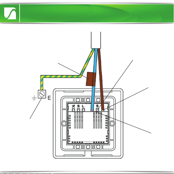
5. Connect the wiring as per the wiring diagram on the following page.
Ensure that the terminals are properly tightened and that no bare wire is
visible. Be aware that existing wiring circuits are not always correctly
coloured, and that there may be other wired connections present in the back
box; if in doubt, always seek the advise of a qualified electrician.
NOTE: The Dimmer does NOT require a mains neutral wire to be connected
it only requires ‘live in’ and ‘switched live out’.
7. Screw the Dimmer Switch to the
mounting box and ensure that the
screws are suciently tight to support
the product, but do not over tighten as
this may cause the chassis to bend.
Ensure that the plastic spacer is
correctly aligned and that no wires are
trapped between the Dimmer Switch
and the back of the back box.
6. Any earth wires present must be attached either to the earth terminal
located in the back box or capped with a strip connector. The Dimmers are
double insulated so are not required to be earthed directly.
Installation
Installation
Signal Cable Connection
for use with LightwaveRF
2-Way Dimmer only
(LOW VOLTAGE: Do not
connect to live mains!)
Earth wire connects
to terminal in back
box (can be capped
o instead if no
terminal present)
Live Wire In. This
should be Brown
or Red in Colour.
Switched Live
Wire Out. This
should be
blue or black
in Colour.
The Switched Live may
be marked by brown/red
tape to emphasise that
it is not a neutral wire.
NOTE: Wiring shown for one of two
gangs. Please repeat for other gang.

8. Replace the plate – a ‘click’ sound
should be heard to signify that the
plate has been correctly replaced.
• It is recommended that LightwaveRF Dimmer Switches be positioned at
least 30cm apart in order to prevent the risk of any radio conflict that could
disrupt remote operation.
• Suitable lamps must be used with the Dimmer or it will not function
correctly. See next section for compatibility information.
Important things to Consider
• In a multigang Dimmer, to be able to
operate any gang by remote control
mains electricity must always be
connected to the rightmost (when
viewed from the front) Dimmer
terminals.
Installation
Compatibility
Ensuring the compatibility of your lamps (bulbs) with LightwaveRF Dimmers
will ensure that you get the best experience from your lighting setup.
LightwaveRF Dimmers are compatible with
• Standard mains voltage incandescent & low energy incandescent lighting
(min 20W, max 250W)
• GU10 and equivalent HI spot mains halogen lamps
• Dimmable Electronic Low Voltage Transformers (20W - 250W max.)
• Inductive Transformers (40 – 170VA max.)
• Selected dimmable (only) LED lamps (see www.lightwaverf.com for further
guidance and information).
LightwaveRF Dimmers are NOT compatible with
• Wirewound transformers (generally older style)
• Electric motors
• Non dimmable LEDs
• CFLs
• CFL tube arrays
Compatibility & Lamps

Adjusting the dimming range
On initial setup, LightwaveRF Dimmers are pre-programmed to allow a
moderate range of dimming for any connected lamps. If desired, this range
can be extended by following the instructions below.
The reason for allowing modifications to the dimming range is to maximise
compatibility with dimmable LED lamps (bulbs). In some cases, LED lamps
may flicker slightly at high or low brightness levels, especially if there is only
a modest overall circuit load (under 10W). Stability can be achieved by a
very slight adjustment to the dimming range of the LightwaveRF Dimmer.
The default setting (smallest dimming range) is the most stable for LEDs. If
the LEDs perform normally at this setting (most cases), then the range can
be increased (if desired) using the following method.
Compatibility & Lamps
1. On the Dimmer switch press and hold
down both the ‘on’ and ‘o’ buttons on
either gang until the blue and amber
LEDs flash alternately then release them.
The Dimmer Switch is now in linking
mode.
Compatibility & Lamps
2. Tap the (top) ‘on’ button twice to enter
Dimming Range Setup. The blue LED will
flash to indicate that the setup menu has
been accessed. The Dimmer will automati-
cally turn on at a high level of brightness.
This indicates that the smallest (most
stable) dimming range is currently selected.
3. Tap the ‘o’ button to gradually increase
the dimming range (indicated by the
incremental decrease in lamp light level).
Keep going until flicker is observed. At this
point, return to the previous stable increment
(optimum level) by pressing the ‘on’ button.
Dimming Range Setup allows the Dimmer’s range to be adjusted to one of
5 dierent presets. If the dimmable LED lamps on the circuit perform
properly at the initial setting (smallest range), then the range can be gradu-
ally increased until (any) flicker is observed. The optimum setting is the one
which provides the greatest range (dimmest setting) without any flicker.
4. Once the optimum level has been achieved, save the setting and leave
setup by holding the on & o buttons until the blue LED flashes quickly.

Compatibility & Lamps
Important things to Consider
• Wattage ratings for the Dimmers are per gang. This means that a total
load
of 250W (incandescent) can be put on each circuit connected to each
gang.
• LightwaveRF Dimmers utilise a tiny amount of power to drive the electron-
ics that operate the RF radio and dimming components. As a result, it is
normal to experience a 5-10% reduction in light output when using
incandescent lamps (bulbs). In the vast majority of cases, this should not be
noticeable as the drop is very small.
• ONLY Dimmable lamps can be used even if the Dimmers are used solely to
switch between the on and o states without dimming. This is because the
technology used in an electronic dimmer is fundamentally dierent to that
of a simple on/o switch and requires compatible lamp technology.
• Electronic Transformers can be used only if they are dimmable. Please
check carefully that the loading and lamp compatibility is appropriate.

• Up to six 2-Way Dimmers (six gangs) can be connected to a standard
LightwaveRF Dimmer Switch. Each 2-Way can be connected directly to the
standard Dimmer, or connected to each other in a ‘daisy-chain’. This
provides an alternative to using intermediate switches (maximum cable
length of 100m)
• The 2-Way Dimmers use standard 3-core connecting wires; however,
because they are electronic dimmers, they utilise one of the cores as a
signal cable (‘S’) running between the Dimmers (as shown on the diagram).
This is low voltage only and should not be connected to 230V mains.
Important: Never install and run power to a 2-Way slave Dimmer before
first installing and connecting the master LightwaveRF Dimmer. Serious
damage could be caused to the unit.
Connecting to a 2-Way Dimmer
• Any LightwaveRF Dimmer Switch (and any gang in a multigang Dimmer)
can be used in conjunction with a LightwaveRF 2-Way Dimmer to perform
2-Way Switching. For full instructions on how to install a 2-Way Dimmer,
please consult the instruction booklet for the 2-Way Dimmer.
Important: The Dimmer must be used with a LightwaveRF 2-Way Dimmer
and cannot be used with an other LightwaveRF Dimmer or a standard
lightswitch. This will cause damage to the Dimmer.
2-Way Switching

IMPORTANT: The signal cable input
marked ‘S’ must ONLY be connected
to the wire running to the other
Dimmer NOT live mains; this will
cause irreparable damage.
3-Core
Cable
From Lighting Circuit
Live
Live
Earth
Switched Live
Signal Cable
Switched Live
2-Way Switching

Setup
Linking the Dimmer to LightwaveRF Controllers
LightwaveRF Dimmers each have 6unique memories which means they can
link with up to 6 LightwaveRF Controllers in total.
NOTE: If you are using a smartphone/tablet to control the Dimmer via the
Lightwave Link, this will always count as ONE controller and take up one
memory slot even if you are using multiple smartphones/tablets.
1. On the Dimmer Switch, press and
hold down both the ‘on’ and ‘o’
buttons until the blue and amber
LEDs flash alternately then release
them. The Dimmer switch is now in
linking mode.
2. Using a LightwaveRF Controller or
smartphone app, press the button
intended to be linked; the blue light
on the Dimmer Switch will flash to
confirm that the remote is now linked.
Setup

Setup
NOTE: Linking Mode lasts for 12 seconds; if no signal is received from a
remote handset during this time then the Dimmer will automatically exit
learning mode without linking the device.
If, when expecting a blue LED flash to confirm pairing, a slow amber LED
flash is received instead, the Dimmer switch memory is FULL and no further
remotes may be linked with it unless one of the existing remotes is first
unpaired (see below).
1. On the Dimmer Switch, press and hold
down both the ‘o’ and ‘on’ buttons
until the blue and amber LEDs flash
alternately then release them. The
Dimmer switch is now in linking mode.
2. Using a LightwaveRF Connect
Remote or app, press the button
intended to be unlinked; the amber light
on the Dimmer Switch will flash quickly
to confirm that the remote is now
unlinked.
photo
Unlinking Remotes and clearing the Dimmer memory
Removing single Device:
Setup

NOTE: Reliable range of operation is around 15m indoors and up to 100m
outdoors (using a Lightwave Link). This figure may vary depending upon
the environment; very thick walls, bodies of water or large metal objects
may interfere with radio range.
If the distance between the transmitter and receiver is too great to achieve
reliable operation, the LightwaveRF Signal Booster may be used in
conjunction with this product to increase the range.
Clearing Memory (will remove all linked remotes):
1. Press and hold down both the ‘on’ and
‘o’ buttons until the blue and amber
LEDs flash alternately then release. The
Dimmer Switch is now in linking mode.
2. On the Dimmer Switch, press and
hold down the ‘o’ button again until
the blue and amber LEDs flash simulta-
neously, then tap (don’t hold) the ‘o’
button a further time; the amber LED
will flash to confirm that the memory
has been cleared.
Setup
Table of contents
Popular Switch manuals by other brands

ZyXEL Communications
ZyXEL Communications MES-3528 - user guide

Perle
Perle IDS-509PP Hardware installation guide

TRENDnet
TRENDnet TE100-H24R Specifications

Pretorian
Pretorian EnvirON Switch 125 instructions

Siemens
Siemens RUGGEDCOM RS900GP installation manual

Broadcast Tools
Broadcast Tools Universal 4.1 MLR Installation and operation manual


NETGEAR
NETGEAR ProSafe Plus JGS524E installation guide

Siemens
Siemens VBFS321F installation instructions

Enerwave
Enerwave ZWN-RSM1 Operation manual

Cisco
Cisco 2975 - Catalyst LAN Base Switch Product bulletin

TP-Link
TP-Link TL-SG605E installation guide

SMC Networks
SMC Networks 6900FSC - annexe 1 Management guide