Megatron ETA25PM Series Owner's manual

FB031
September 7. 2016
Page 1von 9
Programming manual for A(PM) multiturn rotary encoders with
programmable effective electrical angle and sense of rotation
(output signals 4…20 mA, 0-10V or 0-5V)
MEGATRON Elektronik GmbH & Co . KG
Hermann-Oberth-Strasse 7
85640 Putzbrunn / Munich
Germany
Programming Manual
for series ETA25PM, ETA25FPM, ETA25KPM,
HTA36PM,MABxxAPM
Series
ETA25PM
ETA25PM
ETA25PM
Design
Option
F
R
K
Series
ETA25PM
MABxxAPM
Design
Option
TS
(On request, only with
MOQ orderable)
-
Series
ETA25FPM
ETA25KPM
Design
Option
-
-
Series
HTA36 PM
HTA36 PM
HTA36 PM
Design
Option
S (solid shaft)
H (hollow shaft –
screw fixation)
HK (hollow shaft –
clamp fixation)
Table 1: Overview of the user programmable multiturn sensors

FB031
September 7. 2016
Page 2von 9
Programming manual for A(PM) multiturn rotary encoders with
programmable effective electrical angle and sense of rotation
(output signals 4…20 mA, 0-10V or 0-5V)
MEGATRON Elektronik GmbH & Co . KG
Hermann-Oberth-Strasse 7
85640 Putzbrunn / Munich
Germany
1. State of delivery
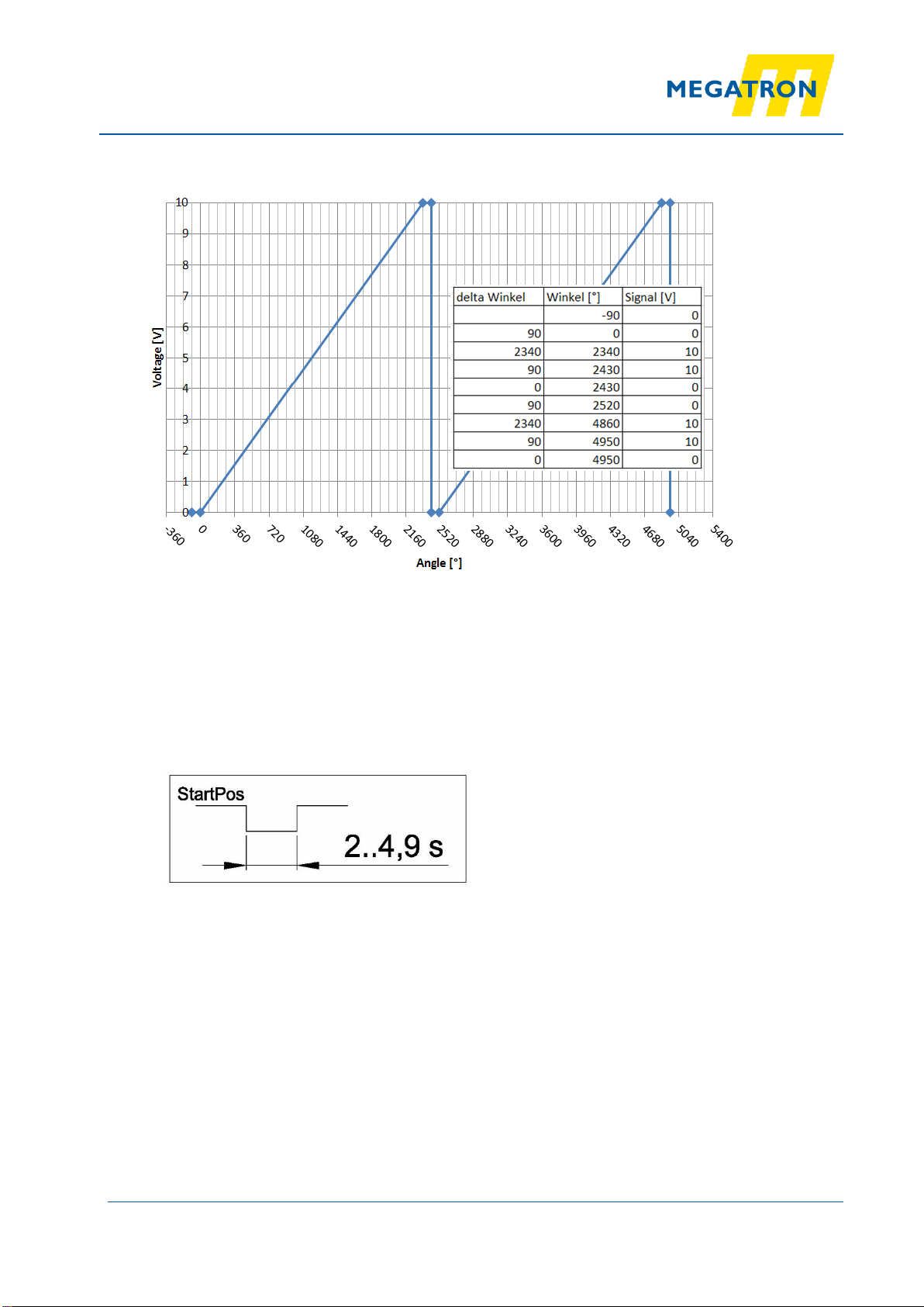
2. Picture 1: Signal output multi-turn encoder state of delivery
At the state of delivery there is an electrical angle of 10 turns adjusted (3600°).
The signal is increasing if you turn the shaft clockwise while you view on the shaft end.
Before the starting point and after the end of the signal transition there is a plateau of a half turn each
side (180°). That means the signal has a periodicity of 11 turns.
FB031
September 7. 2016
Page 3von 9
Programming manual for A(PM) multiturn rotary encoders with
programmable effective electrical angle and sense of rotation
(output signals 4…20 mA, 0-10V or 0-5V)
MEGATRON Elektronik GmbH & Co . KG
Hermann-Oberth-Strasse 7
85640 Putzbrunn / Munich
Germany
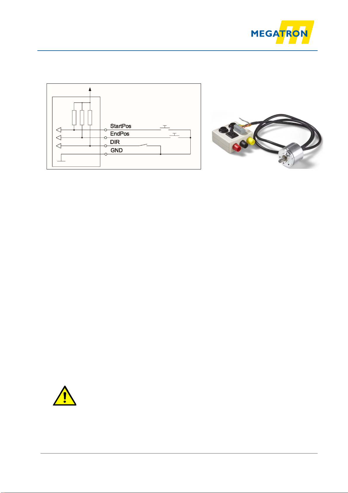
2.2 Function of the Control Inputs StartPos, EndPos and turning Direction DIR (CW,
CCW)
Picture 2: Interface to adjust the encoder signal Picture 3: Optional external
(internal Pull-Up: 470 Ohm against 3.3V) programmer orderable from Megatron
In order to parameterize a programmable multiturn angle sensor, a circuit must be made as shown
in picture 2, consisting of two push buttons and one switch. Alternatively, an external programmer
(picture 3, smart box) can be ordered from Megatron, which has already integrated the circuit as shown
in picture 2.
This manual is applicable to both, for a self-built circuit (as shown in picture 2) or an
external programmer (picture 3, smart-box).
Further information regarding the external programmer can be found on the last page (page 9) of this
manual.
The control inputs StartPos, EndPos and DIR can be switched by manual contacts or you can connect it
with a control unit (PLC). Please take care to connect the ground potential of the encoder properly with
the control unit. The signal inputs should be driven by relais contacts or open-collector outputs. If you put
24V at the signal inputs you would not harm the sensor because it is protected. But you should avoid this
because it could interfere your output signal in the measurement mode.
That means after you have adjusted the sensor (details see below) there should NOT be a 24V voltage
source at the control inputs.
The input line DIR to define the direction of rotation is read in the adjusting mode and in the reset mode
(but not in the reference mode).
If you need a CCW sense of rotation you should connect the input DIR with ground.
For CW sense of rotation you can leave the input not connected.
Please take care
If you program start and stop, the turning sense has to be conform with the DIR input
signal. That means in case of DIR signal input “High” (or not connected) you should
turn the shaft clockwise to adjust the end position afterwards. If you need a counter
clockwise signal output you have to tie the DIR input down to ground. If you do not stick
to this rule your sensor does not function correctly.
Please note that the start and end position is stored in a flash memory. Because of this
you should not do more than 10 000 adjusting cycles.

FB031
September 7. 2016
Page 4von 9
Programming manual for A(PM) multiturn rotary encoders with
programmable effective electrical angle and sense of rotation
(output signals 4…20 mA, 0-10V or 0-5V)
MEGATRON Elektronik GmbH & Co . KG
Hermann-Oberth-Strasse 7
85640 Putzbrunn / Munich
Germany
3. Programming Modes
3.1 Teach-In Mode
With the angle adjust mode you can define (teach in) the start- and end position and the turning
sense in accordance with the sensor shaft movement.
Picture 4: Start of the angle adjust mode
To activate the angle adjust mode please switch the input line StartPos according to the above
picture. At the same time you set the start position. That means the beginning of the signal
transition is adjusted at the current shaft position. Afterwards the sensor should be moved to the
end position. Please take care to do this in accordance with the signal input DIR. At the beginning
of the movement away from the start position (0V or 4mA) the sensor does not know the correct
slope. Because of this the output signal slope is based on the maximum number of turns 10V/200
rev. (16mA/200 rev.)
When you set the end position the maximum signal level is set at the current shaft position
(10V respectively 20mA).
Picture 5: Setting of the end position and closing the angle adjustment mode.
Afterwards the internal micro controller calculates the signal characteristic line. For this purpose
the distance to the next full turn is rounded up and the difference angle is divided into two equal
parts that are set as plateaus beyond the StartPos and the EndPos.
FB031
September 7. 2016
Page 5von 9
Programming manual for A(PM) multiturn rotary encoders with
programmable effective electrical angle and sense of rotation
(output signals 4…20 mA, 0-10V or 0-5V)
MEGATRON Elektronik GmbH & Co . KG
Hermann-Oberth-Strasse 7
85640 Putzbrunn / Munich
Germany
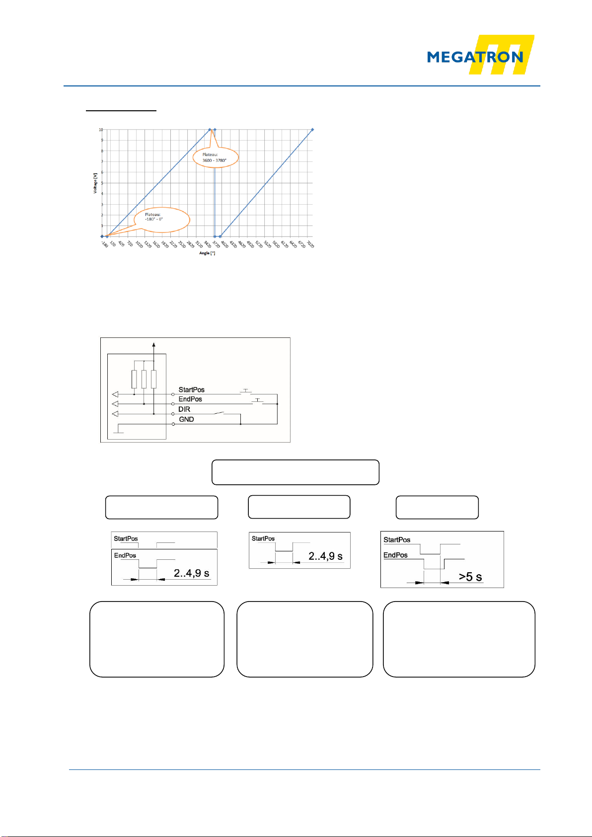
Example how the signal characteristic and the plateaus are calculated
Picture 5: Example how to adjust StartPos, sense of rotation (DIR) and the EndPos
Signalslope over 6.5 rev. = 6,5 * 360° = 2340°
Periodicity 7,0 rev. = 7,0 * 360° = 2520°
Difference 180°
Width of the plateaus 2x90°
3.2 Reference mode
Picture 6: Readjustment of the zero position
After setting the control input StartPos according to the above time interval, the zero
point (minimum signal level) is moved to the current shaft position. The electrical signal
angle and the turning sense are not affected. The signal input DIR is not considered.
This function is helpful if the sensor was moved without power supply more than
±179° and due to this lost the reference to the zero point of the multi turn information.

FB031
September 7. 2016
Page 6von 9
Programming manual for A(PM) multiturn rotary encoders with
programmable effective electrical angle and sense of rotation
(output signals 4…20 mA, 0-10V or 0-5V)
MEGATRON Elektronik GmbH & Co . KG
Hermann-Oberth-Strasse 7
85640 Putzbrunn / Munich
Germany
3.3 Reset Mode –to reset the electrical Angle to Delivery State
Picture 7: Resetmode
If you switch both control inputs StartPos and EndPos according to picture 6, the
electrical angle will be reset to the delivery state (10-turns).
Furthermore the zero position of the signal will be moved to the current signal position
and the turning sense is set according to the state of the DIR input.
That means if DIR is not connected you will get a clockwise signal characteristic
4. Technical Data
Table 2: Technical Data
The single turn encoders (MAB36APS, MAB40APS, MAB50APS) have been cancelled
because you can utilize all the functions with the adjustment procedurtes of the multiturn
encoders. But please note that the timing requirements have been changed in comparision
with the former firware.
Minimum electrical angle
10°
Maximum electrical angle
72 000° (200 Udr.)
Maximum number of adjustment cycles
(flash-storage write cycles)
10 000
Resolution
>= 360°
180°
90°
45°
12 Bit
11 Bit
10 Bit
9 Bit
FB031
September 7. 2016
Page 7von 9
Programming manual for A(PM) multiturn rotary encoders with
programmable effective electrical angle and sense of rotation
(output signals 4…20 mA, 0-10V or 0-5V)
MEGATRON Elektronik GmbH & Co . KG
Hermann-Oberth-Strasse 7
85640 Putzbrunn / Munich
Germany
Programming
State of delivery: 10-turn + 2x Plateau (0,5 rev). The zero point is not positioned.
The sense of rotation is CW (with DIR input not connected). If you need sense of rotation
CCW please connect DIR with GND meanwhile programming.
Afterwards you can disconnect (but this is not a must).
Programming Modes
Teach-In Mode
Reference Mode
Reset Mode
Teach StartPos and EndPos
Take care:
Startpos is the minimum signal
level.
Please take care to connect the
DIR-Input accordingly!
Moves the zero position to the
current position.
The programmed angle is not
affected
Moves the zero position to the
current position.
The sense of rotation is
programmed according to the input
signal.
Output siganal10-turn with Plateaus
Programming interface with internal
„Pull-Up-Resistors“

FB031
September 7. 2016
Page 8von 9
Programming manual for A(PM) multiturn rotary encoders with
programmable effective electrical angle and sense of rotation
(output signals 4…20 mA, 0-10V or 0-5V)
MEGATRON Elektronik GmbH & Co . KG
Hermann-Oberth-Strasse 7
85640 Putzbrunn / Munich
Germany
Programming instructions for special version: ETA25PM 6,35 12 2410 (with integrated switch
and push button switches for programming procedure)
Programming status at delivery:
(START and ZERO position not set to a mechanical reference)
Teach-in procedure (Teach-in modus):
▪Turn sensor to desired START position and press START button
LED starts flashing RED at 4 Hz for 2s and changes to 2 Hz from 2s to 5s
▪Release button when LED starts flashing at 2 Hz after 5s LED lights in RED continuously (=
confirmation of START position)
▪Turn sensor to desired END position and press END button:
The RED LED light disappears and starts flashing GREEN at 4 Hz for 2s and changes to continuously
light in GREEN for 5s
▪Release button when LED starts to light continuously after 5s the LED goes out (= confirmation of
END position)
In case of false sense of rotation (e.g. CW/CCW-switch set to CW, teach-in was done CCW) LED starts
to flash alternating from RED to GREEN (= fault indication) after 4-8s
FYI: START position at teach-in is set to ZERO-degree location of effective electrical travel
Setting ZERO-degree location (Reference modus):
▪Turn sensor to desired ZERO position and press START button
▪LED starts flashing RED at 4 Hz for 2s
▪Release button when LED starts to flash
LED lights in RED continuously for 5s and goes out afterwards (= confirmation of ZERO position)
Reset to status at delivery (Reset modus):
▪Press START and END button simultaneously
▪LED starts flashing RED and GREEN at 4 Hz for 5s
▪Release buttons when LED starts to light continuously
LED lights continuously in RED and GREEN for 5s and goes out (= confirmation of reset)

FB031
September 7. 2016
Page 9von 9
Programming manual for A(PM) multiturn rotary encoders with
programmable effective electrical angle and sense of rotation
(output signals 4…20 mA, 0-10V or 0-5V)
MEGATRON Elektronik GmbH & Co . KG
Hermann-Oberth-Strasse 7
85640 Putzbrunn / Munich
Germany
Programmer (Smart-Box) for (A)PM
Multiturn rotary encoders
Subject to change without notice.
1
2
3
5
4
Switch for
sense of
rotation
END
push
button
START
push
button
Clamping
terminals
for electrical
connection
to rotary
encoder
Banana
sockets for
connection
with power
supply
RED
BLACK
YELLOW
1
2
3
4
5
This manual suits for next models
4
Popular Media Converter manuals by other brands

Sonos
Sonos Multi-Room Music System user guide

Data Conversion Systems
Data Conversion Systems dCS Puccini U-Clock user manual

AxelTech
AxelTech Falcon Series user manual
Schnick-Schnack-Systems
Schnick-Schnack-Systems DPB Pixel-Router Pro user guide

Matrox
Matrox 6150 Encoder user guide

B.M.C.
B.M.C. DAC I quick start guide


