meier elektronik MiniPilot User manual

User guide
Page 1 of 29
Meier Elektronik AG –Gewerbezone 61 –6018 Buttisholz –Tel. 041 497 31 04 –Fax. 041 497 35 07
Small radio for long distances
Document version: 0.8
Author: M. Kurmann
Version overview
Date
Version
Description
10.12.2014
0.1
Created
11.11.2015
0.2
Bug in Table 6 fixed
05.01.2017
0.3
Connection with 7-pole plug to star-delta and soft starter control
documented.
10.01.2017
0.4
Connection diagram 24V (standard)
25.10.2017
0.5
Adaptation scheme 7 pole connector with softstarter
12.03.2018
0.6
Images of new housing inserted
08.04.2019
0.7
Supplement to chapter 7: System extension with a NiveauPilot
08.08.2019
0.8
Adaptation/verification in accordance with the new RED standards
(adaptation of the CE Declaration of Conformity)
M IN IPILOT

User guide
Page 2 of 29
Meier Elektronik AG –Gewerbezone 61 –6018 Buttisholz –Tel. 041 497 31 04 –Fax. 041 497 35 07
Content
1Introduction....................................................................................................................................... 3
2Safety instructions............................................................................................................................ 4
3Scope of delivery.............................................................................................................................. 5
4Hand-held transmitter....................................................................................................................... 5
4.1 General description ................................................................................................................. 5
4.2 Inserting the batteries.............................................................................................................. 6
4.3 Mounting belt clip..................................................................................................................... 7
4.4 Assembling lanyard ................................................................................................................. 8
4.5 Battery replacement ................................................................................................................ 8
5Receiver ........................................................................................................................................... 9
5.1 General.................................................................................................................................... 9
5.2 Housing dimensions and mounting options............................................................................. 9
5.3 Assembly instructions............................................................................................................ 10
5.4 Installation without receiver round plug and without integrated 400V ~ power supply ......... 11
5.5 Installation with receiver round plug and integrated 400V ~ power supply........................... 14
5.5.1 General.............................................................................................................................. 14
5.5.2 Connecting MiniPilot with 7 pole plug to the star-delta control.......................................... 16
5.5.3 Connection MiniPilot with 7 pole plug to the softstarter control......................................... 17
5.6 Installation with receiver round plug and integrated 400V ~ power supply........................... 18
5.6.1 General.............................................................................................................................. 18
5.6.1 Connecting MiniPilot with 7 pole plug to the star-delta control.......................................... 19
5.6.1 Connection MiniPilot with 7 pole plug to the softstarter control......................................... 20
5.7 Configuration ......................................................................................................................... 21
5.7.1 Commonly available functions........................................................................................... 21
5.7.2 DIP switch settings ............................................................................................................ 21
5.7.3 Log in a transmitter............................................................................................................ 22
5.8 Replacing fuses..................................................................................................................... 23
6System extension with a NiveauPilot (optional)............................................................................. 24
7Troubleshooting.............................................................................................................................. 25
8Intended use................................................................................................................................... 25
9Technical specifications ................................................................................................................. 26
10 CE Declaration of Conformity......................................................................................................... 28
11 Test certificates.............................................................................................................................. 29

User guide
Page 3 of 29
Meier Elektronik AG –Gewerbezone 61 –6018 Buttisholz –Tel. 041 497 31 04 –Fax. 041 497 35 07
1 Introduction
The MiniPilot radio system consists of a transmitter and a receiver. Communication takes place in both
directions between transmitter and receiver. This allows the relay states to be displayed as feedback
on the transmitter.
Thanks to sophisticated wireless technology, a range of up to 700 m can be realised even without line
of sight. However, the distance depends on the topology.
The transmitter has 6 robust and weatherproof silicone buttons with a pleasant tactile feedback. They
are backlit and signal the relay status of each function. The labelling can be customised and is made
robust and high-quality by means of thermal transfer printing.
The receiver has 4 relay outputs which can switch 400V ~/8A.
In addition, the receiver has 4 different function programs, a boost mode for range extension up to 700
m and on/off key lock. These functions can be changed independently by the user.
By logging the transmitter into the receiver, you can connect a transmitter very easily to the receiver
and thus receive a unique code so that MiniPilot systems running parallel do not affect each other.

User guide
Page 4 of 29
Meier Elektronik AG –Gewerbezone 61 –6018 Buttisholz –Tel. 041 497 31 04 –Fax. 041 497 35 07
2 Safety instructions
The installation, service and settings of the receiver may only be carried out by electrically
trained personnel.
It is imperative that all installation and safety standards are adhered to.
Before commissioning, check the receiver type plate to see if the correct operating voltage
is used in terms of power and voltage.
The switchgear must not be operated unearthed.
The receiver terminal box may only be opened when currentless.
Never work under voltage on the terminals or on the controller!
Never wash the device with water or clean it with high pressure water.
If the receiver is subject to vibration, it must be mounted on rubber buffers so as not to
shorten its service life.
The MiniPilot radio remote control must NOT be used for safety-relevant applications
where a defect or malfunction of the product may endanger persons or cause material
damage.

User guide
Page 5 of 29
Meier Elektronik AG –Gewerbezone 61 –6018 Buttisholz –Tel. 041 497 31 04 –Fax. 041 497 35 07
3 Scope of delivery
The following items are included in the scope of delivery of the MiniPilot:
- Transmitter
- 2 x AAA alkaline batteries
- Receiver
- Receiver antenna with SMA screw connection
- Belt clip with adhesive tape for self-assembly when desired.
- Lanyard
- Lettering (optional)
- External 230V ~ plug-in power supply (optional)
- External 400V ~ plug-in power supply (optional)
- 400V ~ power supply (optional) integrated in the receiver
- Connector (optional)
- Connection cable (optional)
- Fastening straps for the receiver (optional)
4 Hand-held transmitter
4.1 General description
Figure 1: Transmitter view front side
The transmitter has 6 backlit buttons that can
indicate the status of the relays. Depending on the
program selected, the buttons have different
functions or different relay functions are
performed.
An optional label describes the corresponding
functions.
If the key lock is activated, the transmitter must
first be unlocked by pressing the button 5. Only
then are the functions with relay control possible.
If all buttons flash at 5s, the batteries are low and
must be replaced.
If a button is flashing, the receiver is out of range
or not switched on.

User guide
Page 6 of 29
Meier Elektronik AG –Gewerbezone 61 –6018 Buttisholz –Tel. 041 497 31 04 –Fax. 041 497 35 07
Figure 2: Transmitter view on the back
Item 1: Transmitter
Item 2: Belt clip
Item 3: lanyard
Item 4: Battery compartment
4.2 Inserting the batteries
The transmitter comes with batteries (2 x AAA alkaline) included. These must be inserted first.
Step 1:
Loosen the four screws with a small cross-head
screwdriver
1
2
3
4

User guide
Page 7 of 29
Meier Elektronik AG –Gewerbezone 61 –6018 Buttisholz –Tel. 041 497 31 04 –Fax. 041 497 35 07
Step 2:
Insert the new batteries. Pay attention to the
correct polarity
Step 3:
Briefly press button 5. When it starts to flash, the
batteries are inserted correctly.
4.3 Mounting belt clip
Remove the adhesive tape liner on the belt clip and press in on the back of the transmitter.
Figure 3: Assembling belt clip
+
+

User guide
Page 8 of 29
Meier Elektronik AG –Gewerbezone 61 –6018 Buttisholz –Tel. 041 497 31 04 –Fax. 041 497 35 07
4.4 Assembling lanyard
Open the lanyard fastener and insert it into the eyelet of the belt clip.
Figure 4: Assembling lanyard
4.5 Battery replacement
Remove the two screws on the back (see item 5, Figure 2, page 6), you can remove the back of the
MiniPilot housing (see procedure in section 4.2, page 6)
For the device to work properly, use 1.5V AAA or LR3 alkaline batteries. The
batteries can be purchased from the company Meier Elektronik AG or in specialist
shops.

User guide
Page 9 of 29
Meier Elektronik AG –Gewerbezone 61 –6018 Buttisholz –Tel. 041 497 31 04 –Fax. 041 497 35 07
5 Receiver
5.1 General
The receiver has a power supply and a silicone button on the front. If the receiver is connected to the
power supply, the power LED lights up. However, the silicone button does not light up. The silicone
button is used to register new stations or newly configured stations (see Page 21).
5.2 Housing dimensions and mounting options
The receiver housing can be mounted in different ways. Depending on the mounting option, the
receiver can be mounted on a DIN rail, with tabs, on rubber bumpers, with a magnet or with U-bolts.
The corresponding assembly material can be obtained from Meier Elektronik AG.
Figure 5: Receiver housing with mounting holes/thread
If the receiver is used outdoors, it should not be exposed to direct weather
conditions so as not to unnecessarily reduce its service life.
Although the receiver is weatherproof, you should protect the receiver from
splashes of water and other environmental effects.

User guide
Page 10 of 29
Meier Elektronik AG –Gewerbezone 61 –6018 Buttisholz –Tel. 041 497 31 04 –Fax. 041 497 35 07
5.3 Assembly instructions
The best reception properties can be achieved with visual contact. However, since this is usually not
possible, the receiver must be placed with its integrated antenna so that the antenna can emit or
receive as independently as possible.
Figure 6: Receiver installation for optimum reception
It is ideal if the antenna can emit for 2-3 metres
freely. As far as possible, there should be no
obstacles in this area. In addition, the reception
quality can be increased if the receiver is mounted
2-3 metres from the ground.

User guide
Page 11 of 29
Meier Elektronik AG –Gewerbezone 61 –6018 Buttisholz –Tel. 041 497 31 04 –Fax. 041 497 35 07
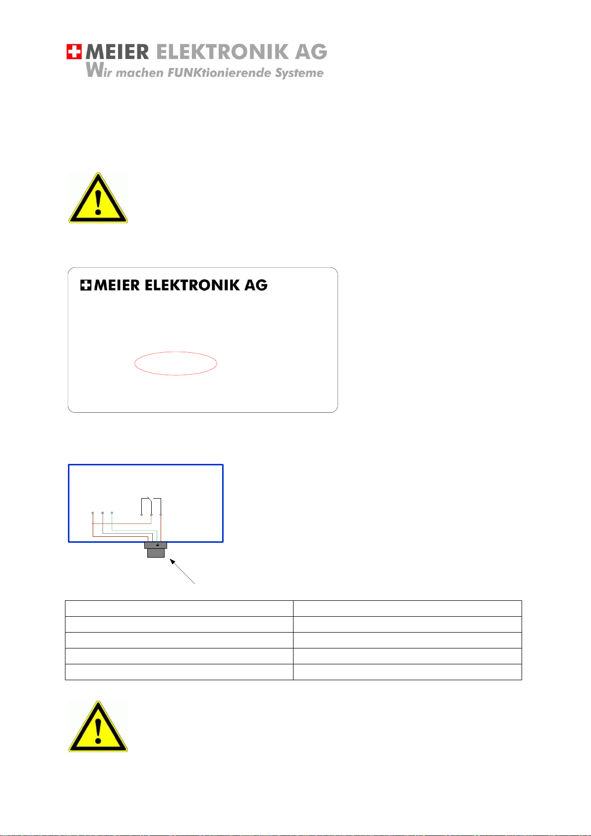
5.4 Installation without receiver round plug and without integrated 400V ~ power
supply
If the receiver does not have a plug option, pass the connection cable through the M screw connection
and wire the device accordingly. To do this, remove the receiver housing cover.
Check the voltage (V) on the receiver type plate with its operating voltage (see
Figure 7).
Please note the equipment printout on the green circuit board for the supply of 9 ...24VDC This
connection is made via screw terminals.
Figure 7: Receiver labels
Figure 8: Connection scheme standard MiniPilot receiver
Gewerbezone 61 –6018 Buttisholz –Tel. 041 497 31 04
www.meier-elektronik.ch
Typ: Rx-Pilot-Mini
Produkt: MINIPILOT
V: 9..24VDC
FRQ: 868MHZ
ID: 00345
14
11
12
14
11
12
14
11
12
14
11
12
+ -
9...24 VDC

User guide
Page 12 of 29
Meier Elektronik AG –Gewerbezone 61 –6018 Buttisholz –Tel. 041 497 31 04 –Fax. 041 497 35 07
Table 1: Pin assignment
The receiver supports a maximum of 4 high quality relay channels. The
contacts are potential-free and always designed as opener/closer (SPDT).
The opener is available at the pin number 12/11 and the closer at 11/14.
The maximum switching voltage of the relays is 400V ~ and is especially
approved for this area!
The relays can be used to directly run 1-phase motors with a maximum
load of 0.3W at 230V!
Use
Connect a flat-head
screwdriver size 1.
DO NOT use ferrules
on the receiver
connection cables!
We can only achieve
an optimal cable
pressure without
ferrules!
By pressing on the front of the plug notch, the press connection opens and
the cables can be inserted. The upper and lower wire terminals are
electrically connected to each other.
Only use one wire/cable per plug hole!
12 11 14
CH1

User guide
Page 13 of 29
Meier Elektronik AG –Gewerbezone 61 –6018 Buttisholz –Tel. 041 497 31 04 –Fax. 041 497 35 07
Table 2: Characteristics of data relay
Max. Continuous current/max. Inrush current [A]
8/15
Rated Voltage/(max) Switching voltage [V ~]
230/400V
Max. Switching capacity AC1 [VA]
2000
Max. Switching capacity AC15 (230V ~) [VA]
400
1-phase motor load, AC3 operation (230V ~) [kW]
0.3
Max. Switching current DC1: 30/110 / 220V [A]
8/0.3/0.12
Min. Switching load [mW, V / mA]
300, 5/5
Figure 9: Electrical lifetime at AC
User guide
Page 14 of 29
Meier Elektronik AG –Gewerbezone 61 –6018 Buttisholz –Tel. 041 497 31 04 –Fax. 041 497 35 07
5.5 Installation with receiver round plug and integrated 400V ~ power supply
5.5.1 General
If the receiver has a plug option, it can be connected via the round socket (4 or 7 pole).
Check the voltage (V) on the receiver type plate with its operating voltage (see
Figure 10).
Figure 10: Receiver labels
Table 3: Pin assignment 4 pole plug
Pin number on receiver plug
Function
1
Supply L1 (400V ~)
2
Supply L2 (400V ~)
3
Relay 1 (CH1) switched L1 (400V ~)
4
PE (earth)
Check the relay load in Table 2, page 13
Gewerbezone 61 –6018 Buttisholz –Tel. 041 497 31 04
www.meier-elektronik.ch
Typ: Rx-Pilot-Mini
Produkt: MINIPILOT
V: 400V~
FRQ: 868MHZ
ID: 00345
12 11 14
CH1
L1 L2 PE …….
MiniPilot Empfänger
21
Empfängerstecker 4 Pol
3

User guide
Page 15 of 29
Meier Elektronik AG –Gewerbezone 61 –6018 Buttisholz –Tel. 041 497 31 04 –Fax. 041 497 35 07
Table 4: Pin assignment 7 pole plug
Pin number on receiver plug
Function
Cable number
1
Supply L1 (400V ~)
1
2
Supply L2 (400V ~)
2
3
Relay Common CH1
3
4
Relay close contact CH1
4
5
Not documented
5
6
Not documented
6
PE (7)
PE (earth)
7/Yellow-green
Check the relay load in Table 2, page 13
L1 L2 PE
MiniPilot Empfänger
21
Empfängerstecker 7 Pol
3 4 5 6
12 11 14
CH1

User guide
Page 16 of 29
Meier Elektronik AG –Gewerbezone 61 –6018 Buttisholz –Tel. 041 497 31 04 –Fax. 041 497 35 07
5.5.2 Connecting MiniPilot with 7 pole plug to the star-delta control
L1 L2 L3 PE U1 V1 W1 U2 V2 W2 PE 1 2 3 PE 4 5 PE
Klemmen
Schützensteuerung
M
Grün / Gelb
1
Kabelnummer
L1 L2 PE
MiniPilot Empfänger
12 11 14
CH1
1 2 3 4 5 6
3
2
4

User guide
Page 17 of 29
Meier Elektronik AG –Gewerbezone 61 –6018 Buttisholz –Tel. 041 497 31 04 –Fax. 041 497 35 07
5.5.3 Connection MiniPilot with 7 pole plug to the softstarter control
1.1
Grün / Gelb
1
Kabelnummer
L1 L2 PE
MiniPilot Empfänger
12 11 14
CH1
1 2 3 4 5 6
3
2
4
1.0
1.3
1.2
1.5
1.4
1.7
1.6
Brücke oder Klixon
PE
Klemmen Softstarter-
Steuerung

User guide
Page 18 of 29
Meier Elektronik AG –Gewerbezone 61 –6018 Buttisholz –Tel. 041 497 31 04 –Fax. 041 497 35 07
5.6 Installation with receiver round plug and integrated 400V ~ power supply
5.6.1 General
If the receiver does not have a plug option, but an integrated 400V ~ power supply, the MiniPilot must
be connected according to the following instructions.
Check the voltage (V) on the receiver type plate with its operating voltage (see
Figure 10).
Figure 11: Receiver labels
Gewerbezone 61 –6018 Buttisholz –Tel. 041 497 31 04
www.meier-elektronik.ch
Typ: Rx-Pilot-Mini
Produkt: MINIPILOT
V: 400V~
FRQ: 868MHZ
ID: 00345

User guide
Page 19 of 29
Meier Elektronik AG –Gewerbezone 61 –6018 Buttisholz –Tel. 041 497 31 04 –Fax. 041 497 35 07
5.6.1 Connecting MiniPilot with 7 pole plug to the star-delta control
MiniPilot Empfänger
L1 L2 L3 PE U1 V1 W1 U2 V2 W2 PE 1 2 3 PE 4 5 PE
Klemmen
Schützensteuerung
M
12 11 14
CH1
L1 L2 PE

User guide
Page 20 of 29
Meier Elektronik AG –Gewerbezone 61 –6018 Buttisholz –Tel. 041 497 31 04 –Fax. 041 497 35 07
5.6.1 Connection MiniPilot with 7 pole plug to the softstarter control
1.1
Grün / Gelb
1
Kabelnummer
3
2
4
1.0
1.3
1.2
1.5
1.4
1.7
1.6
Brücke oder Klixon
PE
Klemmen Softstarter-
Steuerung
MiniPilot Empfänger
12 11 14
CH1
L1 L2 PE
Schaltplannummer Softstarter-Steuerung:
140117
Table of contents


