MELAG ME65010 User manual

Installation instructions
Filling pump
EN
Dear customer,
We thank you for your confidence demonstrated by the purchase of this MELAG product. As an owner-run and operated
family concern founded in 1951, we have a long history of successful specialization in hygiene products for practice-
based use. Our focus on innovation, quality and the highest standards of operational reliability has established MELAG
as the world’s leading manufacturer in the instrument reprocessing and hygiene field.
You, our customer are justified in your demand for the best products, quality and reliability. Providing “competence in
hygiene” and “Quality – made in Germany”, we guarantee that these demands will be met. Our certified quality
management system is subject to close monitoring: one instrument to this end is our annual multi-day audit conducted in
accordance with ENISO13485. This guarantees that all MELAG products are manufactured and tested in accordance
with strict quality criteria.
The MELAG management and team.
This device is to be maintained exclusively by a qualified service technician trained by MELAG and working in
accordance with the valid directives.


Contents
Contents
1 General guidelines ...............................................................................................................................................................4
Symbols used ......................................................................................................................................................................4
Disposal ...............................................................................................................................................................................4
2 Safety.....................................................................................................................................................................................5
3 Description of the device.....................................................................................................................................................6
Intended use ........................................................................................................................................................................6
Scope of delivery .................................................................................................................................................................6
View of filling pump..............................................................................................................................................................6
4 Assembly ..............................................................................................................................................................................7
Vacuclave 550 .....................................................................................................................................................................7
Careclave 618....................................................................................................................................................................10
5 Electrical test in accordance with EN 50678 (VDE 0701) or national standard ............................................................13
6 Maintenance........................................................................................................................................................................14
7 Technical data ....................................................................................................................................................................15
8 Spare parts..........................................................................................................................................................................16

1 General guidelines
4
1 General guidelines
Please read this user manual carefully before using MELAG accessories. It contains important safety instructions.
Please store this user manual carefully and in close proximity to your device. It represents a component of the product.
Should the manual no longer be legible, is damaged or has been lost, you can download a new copy from MELAG
download centre at www.melag.com.
Symbols used
Symbol Description
Indicates a dangerous situation, which if not avoided, could entail slight to life-threatening in-
juries.
Draws your attention to important information.
Disposal
MELAG devices are synonymous with high quality and a long life-span. When you eventually need to decommission your
MELAG device, the required disposal of the device can take place with MELAG in Berlin. Simply contact your stockist.
Dispose of accessories and consumption media which you no longer require in the appropriate manner. Comply with all
relevant disposal specification in terms of possibly contaminated waste.
The packaging protects the device against transport damage. The packaging materials have been selected for their
environmentally-friendly disposability and can be recycled. Returning the packaging to the material flow reduces the
amount of waste and saves raw materials.
MELAG draws the operator’s attention to the fact that they may be legally obliged (e.g. in Germany according to
ElektroG) to remove used batteries and accumulators non-destructively before handing over the device, provided they
are not enclosed in the device.

2 Safety
5
2 Safety
When operating the device, comply with the following safety instructions as well as those contained in sub-
sequent chapters. Use the unit only for the purpose specified in these instructions. Also observe the safety
instructions in the user manual of your steam sterilizer. Failure to comply with the safety instructions can
result in injury and/or damage to the unit.
Assembly and commissioning
nCheck the device after unpacking for any damage suffered during transport.
nThe filling pump may be installed only by an authorized technician who must be a qualified electrician.
Opening the housing of the steam sterilizer
nImproper opening of the steam sterilizer can impair electrical safety and pose a danger to the user. The device may
be opened only by an authorised technician who must be a qualified electrician.

3 Description of the device
6
3 Description of the device
Intended use
The filling pump (art. no. ME65010) is intended for the semi-automatic filling of the feed water tank of the steam sterilizer
with feed water.
The feed water tank can be filled from any feed water supply storage container using the suction hose.
Scope of delivery
Check the scope of delivery before mounting the filling pump on the steam sterilizer.
▪ Installation instructions
▪ Filling pump
▪ 2x Cu seals (13.5x18.5)
▪ Connection screw (G1/4" - A2)
▪ Wiring harness for filling pump (including socket and fastening nut)
View of filling pump
View from the front/side
2
4
1
5
3
1 Feed water connection
2 Electrical connection
3 Connection hose
4 Wellnuts
5 Suction hose with filter

4 Assembly
7
4 Assembly
Vacuclave 550
6
7
8
9
10
11
12
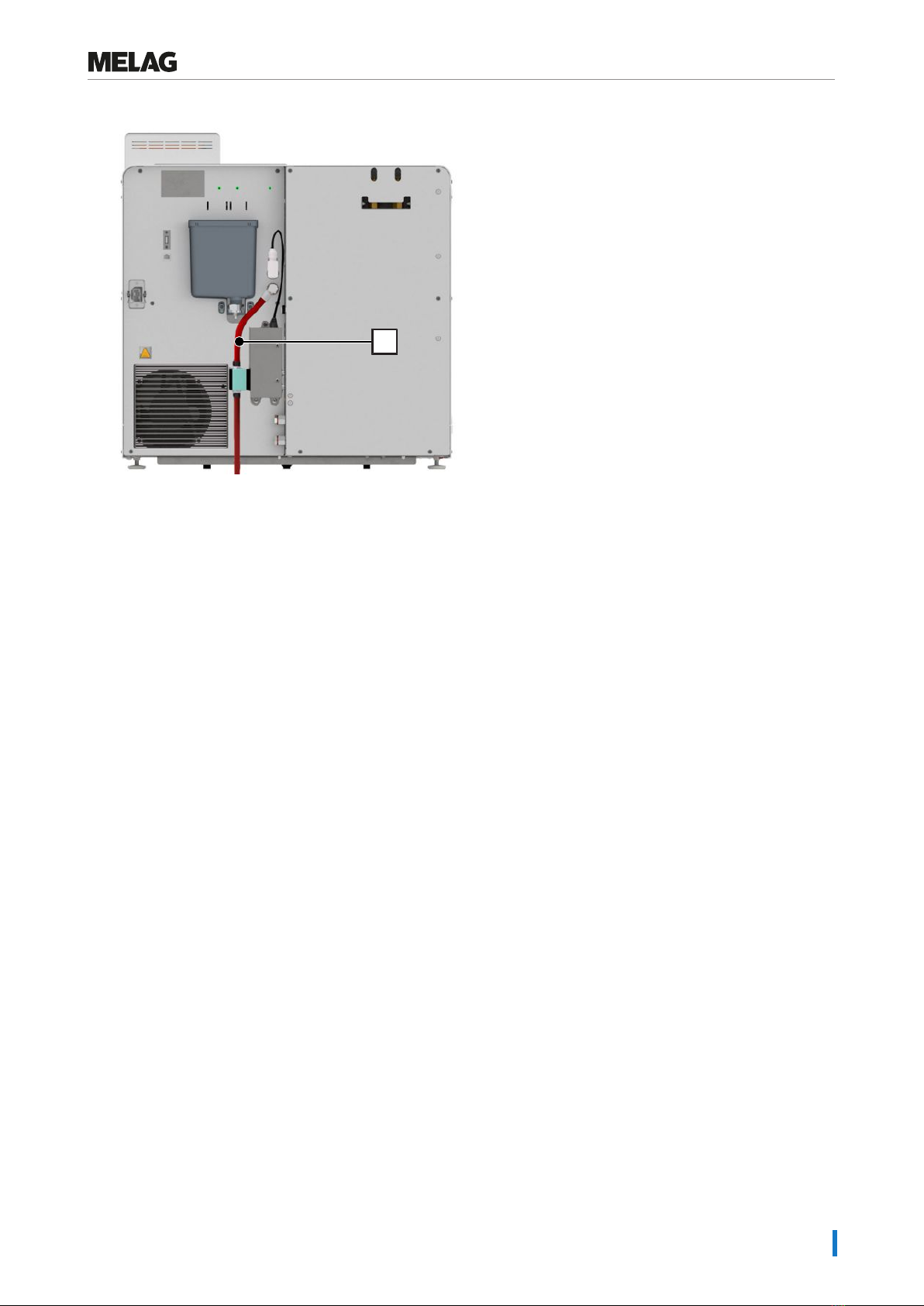
6 Mains cable connection (safety clip)
7 Overflow funnel
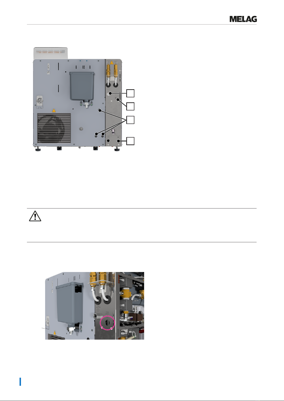
8 Rear device cover (left)
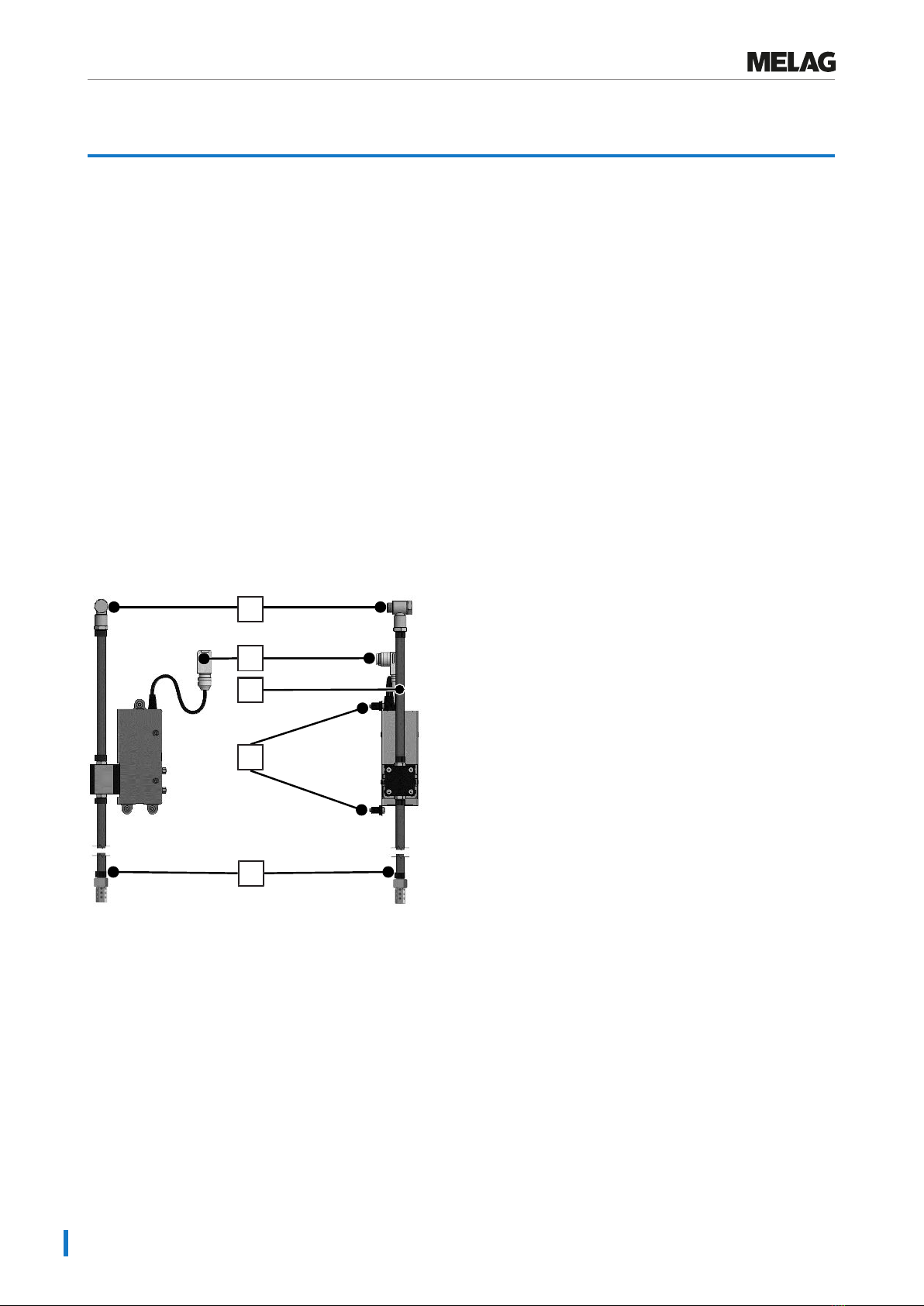
9 Electrical connection of filling pump
(cover plug)
10 Feed water connection of the filling
pump
11 Mounting holes of the filling pump
12 Feed water connection, water treatment
unit
The following must be fulfilled or present:
ü
2x open-end spanner (AF17)
ü
Torx key (TX20)
WARNING
Danger of electric shock from live components
nBefore opening the unit, switch off at the power switch, and remove the plug.
nDetermine the absence of voltage at all poles.
1. Remove the safety clip from the mains cable connection (Pos. 6).
2. Pull the waste water hose off the overflow funnel (Pos. 7).
3. Dismantle the left side of the rear device cover (Pos. 8) by unscrewing the six screws (TX20).
4. Remove the cover plugs of the mounting holes (Pos. 11) from the dismantled device cover.
5. Remove the cover plug from the electrical connection of the filling pump (Pos. 9).
6. Remove the ring nut from the wiring harness supplied for the filling pump.
7. Insert the connection socket from the wiring harness of the filling pump from the inside through the opening of the
electrical connection of the filling pump (Pos.9).
PLEASE NOTE: The detent at the opening of the connection socket determines the alignment.
8. Hand-tighten the ring nut of the wiring harness.

4 Assembly
8
9. Make the electrical connections inside the unit (2 connectors).
10. Insert the wellnuts (Pos. 4) into the mounting holes of the rear device cover (Pos. 11), and tighten the screws.
11. Mount the rear device cover (Pos. 8) with the 6 screws (TX20).
12. Remove the screw plug with Cu seal from the feed water connection of the filling pump (Pos. 10).
NOTICE!Ensure that the feed water connection of the filling pump does not move by holding it in the
opposite direction.
13. Remove the cover plug from the feed water connection, water treatment unit (Pos. 12), and close the connection
with the Cu seal and screw plug from the feed water connection of the filling pump.
14. Fit the feed water connection of the filling pump.
13 13 Connection screw
14
14 Cu seals
15. Screw the connection screw (Pos. 13) into the feed water connection of the filling pump (Pos. 10).

4 Assembly
9
16. Align the connection hose (Pos. 3) according to the illustration.
3
17. Tighten the connection screw (Pos. 13) with two open-end spanners.
NOTICE!Ensure that the feed water connection of the filling pump does not move by holding it in the
opposite direction.
18. Lead the hose into the external storage container. The suction filter (Pos.5) must be guided onto the floor of the
storage container.
NOTICE!Do not lead the filling pump hose over sharp edges. It must run freely downwards and may not be
kinked or pinched.
19. Connect the electrical connection of the filling pump (Pos. 2).
20. Tighten the retainer of the plug.
21. Connect the waste water hose to the overflow funnel.
22. Reattach the safety clip to the power cord connector (Pos.6).
23. Connect the power plug, and switch on the device.
ÊThe steam sterilizer will automatically recognise the filling pump.

4 Assembly
10
Careclave 618
6
7
8
9
6 Feed water connection of the filling
pump
7 Opening for electrical connection, filling
pump
8 Mounting holes of the filling pump
9 Feed water connection, water treatment
unit
The following must be fulfilled or present:
ü
2x open-end spanner (AF17)
ü
Torx key (TX20)
ü
Allen key (SW6)
ü
Piercer and soft-face mallet
ü
Possibly file
WARNING
Danger of electric shock from live components
nBefore opening the unit, switch off at the power switch, and remove the plug.
nDetermine the absence of voltage at all poles.
1. Remove the plastic cover on the rear of the unit.
2. Disassemble the left device cover by unscrewing the three screws (TX20).
3. Use a suitable tool (e.g. a punch and a soft-face mallet) to break out opening for the electrical connection for the
filling pump (Pos. 7).
4. Remove any burrs from the attachment points with a file.
5. Remove the ring nut from the wiring harness supplied for the filling pump.

4 Assembly
11
6. Insert the connection socket of the wiring harness of the filling pump from the inside through the cut-out (Pos. 7).
PLEASE NOTE: The detent at the opening of the connection socket determines the alignment.
7. Hand-tighten the ring nut of the wiring harness.
8. Make the electrical connections inside the unit (2 connectors).
9. Mount the left unit cover.
10. Remove the cover plugs of the mounting holes from the rear device cover (Pos.8).
11. Remove the screw plug with Cu seal from the feed water connection of the filling pump (Pos. 6).
NOTICE!Ensure that the feed water connection of the filling pump does not move by holding it in the
opposite direction.
12. Remove the cover plug from the feed water connection, water treatment unit (Pos. 9), and close the connection with
the Cu seal and screw plug from the feed water connection of the filling pump.
13. Insert the wellnuts (Pos. 4) into the mounting holes of the rear device casing (Pos.8). Tighten the screws of the
wellnuts.
14. Plug the electrical connection of the filling pump (Pos. 2) into the electrical connection of the filling pump on the
steam sterilizer (Pos. 7).
15. Tighten the retainer of the plug.
16. Fit the feed water connection of the filling pump.
10 10 Connection screw
11
11 Cu seals
17. Screw the connection screw (Pos. 10) into the feed water connection of the filling pump (Pos. 6).

4 Assembly
12
18. Align the connection hose (Pos. 3) according to the illustration.
3
19. Tighten the connection screw (Pos. 10) of the filling pump with two open-end spanners.
NOTICE!Ensure that the feed water connection of the filling pump does not move by holding it in the
opposite direction.
20. Lead the hose into the external storage container. The suction filter (Pos.5) must be guided onto the floor of the
storage container.
NOTICE!Do not lead the filling pump hose over sharp edges. It must run freely downwards and may not be
kinked or pinched.
21. Connect the power plug, and switch on the device.
ÊThe steam sterilizer will automatically recognise the filling pump.

5 Electrical test in accordance with EN 50678 (VDE 0701) or national standard
13
5 Electrical test in accordance with EN 50678
(VDE 0701) or national standard
}After closing the unit, perform an electrical test according to EN 50678 (VDE 0701). Comply with the applicable
national specifications.
PLEASE NOTE: The measuring device to be used for these tests must be subject to regular checks and calibration
in accordance with VDE0413 or EN61557.
PLEASE NOTE
For more information, see “Manufacturer's recommendation for electrical test during initial
commissioning, after maintenance or repair”.

6 Maintenance
14
6 Maintenance
PLEASE NOTE
The maintenance work described below can be performed by the user as part of in-house maintenance.
All maintenance activities beyond this may only be carried out by an authorised technician.
Comply with the following for safe handling:
uMaintain the specified maintenance intervals.
uOnly original MELAG spare parts may be used.
Interval Measure Unit component
Daily Check the filling level Storage container
If required or within the scope of equip-
ment maintenance
Clean or replace the suction filter Filter with sieve insert (Pos. 5)

7 Technical data
15
7 Technical data
Supply voltage DC 16 V ( ±1)
Volume flow 1 l/min
Maximum suction lift 1.2m
Maximum installation altitude 3000m
Minimum feed water temperature 5 °C
Maximum feed water temperature 40 °C
Weight, including suction hose approx. 1.5 kg

8 Spare parts
16
8 Spare parts
All specified articles are available through specialist dealers.
Article Art. no.
Silicone hose 12/6 mm, 2 m ME51450
Hose clamp, 12/8 mm ME35480
Filter with sieve insert ME34010
10x Cu seal 1/2” for internal thread ME36060


Your stockist
MELAG Medizintechnik GmbH & Co. KG
Geneststraße 6-10
10829 Berlin
Germany
Email: [email protected]
Web: www.melag.com
Original instructions
Responsible for content: MELAG Medizintechnik GmbH & Co. KG
We reserve the right to technical alterations
ZBA_P10_EN.pdf | Rev. 4 - 23/2702 | Modification date: 2023-10-11
Table of contents
Other MELAG Water Pump manuals
Popular Water Pump manuals by other brands

laguna
laguna PT362 Operation and maintenance guide

KADANT
KADANT LIQUI-MOVER LMHT-500 SERIES Handbook

Franklin Electric
Franklin Electric Little Giant 16 G Series owner's manual

BUSCH
BUSCH COBRA NC 1500 B Installation and maintenance instructions

Barnes
Barnes BAFEZ-1.25x2 Installation and operation manual

Actron
Actron CP7830-101 operating instructions

WOERNER
WOERNER GMV-C Translation of the original operation manual

Samoa
Samoa PM45 Service manual

Briggs & Stratton
Briggs & Stratton Water Transfer Pump Operator's manual

VEVOR
VEVOR KQ-1K operating manual

GUSMER
GUSMER H-2000 Installation instructions and parts identification

Nakayama
Nakayama NP2010 owner's manual