Melexis MLX90132 User manual

MLX90132
13.56MHz RFID / NFC Transceiver
3901090132 Page 1 of 44 Jan-2014
Rev. 009
Features and Benefits
Conforms with ISO/IEC 18092 (NFC)
Conforms with ISO/IEC 14443A and B,
Conforms with ISO/IEC 15693
Conforms with ISO/IEC 18000-3 mode 1
High speed communication (up to 848kbit/s)
Standard SPI/UART interfaces
Built-in Field and TAG detectors
Application Examples
NFC enabled car for access and start
Combo NFC and Wireless Power Charging
solutions
NFC applications in Industrial area (e.g. White
goods, security …)
Ordering Information
Part Code Temperature Code Package Code Option Code Packing Form Code
MLX90132 R (-40°C to 105°C) LQ (Lead free QFN 5x5 32 leads) AEA-000 RE
MLX90132 R (-40°C to 105°C) LQ (Lead free QFN 5x5 32 leads) AEA-000 TU
MLX90132 S (-20°C to 85°C) LQ (Lead free QFN 5x5 32 leads) AEA-000 RE
MLX90132 S (-20°C to 85°C) LQ (Lead free QFN 5x5 32 leads) AEA-000 TU
Functional Diagram
microcontroller
SPI/UART
TX1
RX1
Analog
section
Digital
section
MLX90132
RX2
TX2
Figure 1: MLX90132 functional diagram
Description
The MLX90132 is a 13.56MHz, fully integrated,
multi-protocol RFID/NFC transceiver IC. It has
been designed to handle sub-carrier frequencies
from 106 to 848 kHz and baud rates up to
848kbit/s.
The dual driver architecture of the MLX90132
requires minimal external support components
and allows the transmitter to provide up to
300milliwatts RF power to an appropriate antenna
load. This delivered power is suitable for most
short to mid-range applications.
The MLX90132 embeds tag emulation
functionality to support NFC Peer to Peer passive
communication mode. Enhanced tag and field
detection capabilities provide significant power
consumption reduction in RFID reader
configuration and in NFC mode.
The digital section of the MLX90132 handles the
low protocol layers from API to physical layer
using advanced bit and frame encoding/decoding
functions. It contains a digital demodulator based
on sub-carrier detection and a programmable
bit/symbol encoder/decoder. It also encodes and
decodes the start and stop bits, parity bits, extra
guard time (EGT), start and end of frame
(SOF/EOF) and CRC.
Its 528 byte buffer handles an entire RFID frame.
The SPI/UART communication ports guarantee
easy interface with the majority of
microcontrollers.
Downloaded from Arrow.com.

MLX90132
13.56MHz RFID / NFC Transceiver
3901090132 Page 2 of 44 Jan-2014
Rev. 009
Table of Contents
1 Pin and signal descriptions...............................................................................................................................3
2 General Description..........................................................................................................................................4
3 Power Management and Operating modes......................................................................................................6
4 Start-up sequence ............................................................................................................................................8
5 Communication Interface & protocol ................................................................................................................9
5.1 UART .........................................................................................................................................................9
5.2 SPI ...........................................................................................................................................................10
5.2.1 Polling mode......................................................................................................................................10
5.2.2 IRQ mode ..........................................................................................................................................11
6 Commands .....................................................................................................................................................12
6.1 Command format .....................................................................................................................................12
6.2 List of commands.....................................................................................................................................12
6.3 IDN command (0x01)...............................................................................................................................13
6.4 Protocol select command (0x02) .............................................................................................................13
6.5 PollField command (0x03) .......................................................................................................................18
6.6 SendRecv command (0x04) ....................................................................................................................19
6.6.1 Support of extended frames..............................................................................................................21
6.6.2 List of Error codes .............................................................................................................................22
6.7 Listen command (0x05) ...........................................................................................................................23
6.8 Send command (0x06).............................................................................................................................25
6.9 Idle command (0x07) ...............................................................................................................................26
6.10 BaudRate command (0x0A) ..................................................................................................................28
6.11 SubFreqRes command (0x0B) ..............................................................................................................28
6.12 AcFilter command (0x0D) ......................................................................................................................29
7 Modifying internal settings for optimal performances .....................................................................................30
7.1.1 Example: How to modify the ARC_B register ...................................................................................30
7.1.2 Example how to read back WUFlags content ...................................................................................31
8 Tag Detector ...................................................................................................................................................32
8.1 Operating Principle ..................................................................................................................................32
8.2 Calibration procedure...............................................................................................................................33
9 Field Detector .................................................................................................................................................33
10 Electromagnetic support (EMD) ...................................................................................................................34
11 Application Information .................................................................................................................................37
11.1 External Antenna network......................................................................................................................37
11.2 Application schematic ............................................................................................................................37
12 Electrical Specifications................................................................................................................................38
12.1 Absolute Maximum Ratings ...................................................................................................................38
12.2 DC Characteristics .................................................................................................................................38
12.3 Power Consumption Characteristics......................................................................................................38
12.4 RF Characteristics .................................................................................................................................39
12.5 SPI Characteristics ................................................................................................................................40
12.6 Oscillator Characteristics .......................................................................................................................41
14 ESD Precautions ..........................................................................................................................................42
15 Standard information regarding manufacturability of Melexis products with different soldering processes 42
16 Package Information.....................................................................................................................................43
17 Disclaimer .....................................................................................................................................................44
18 Contact Information ......................................................................................................................................44
Downloaded from Arrow.com.Downloaded from Arrow.com.

MLX90132
13.56MHz RFID / NFC Transceiver
3901090132 Page 3 of 44 Jan-2014
Rev. 009
1 Pin and signal descriptions
The device is packaged in a 32 pin lead free QFN package.
Exposed Pad
(EXP)
NC
NC
NC
NC
NC
NC
NC
NC
VDD
UARTRX/IRQIN
VDC
RX1
RX2
GND_RX
NC
NC
NC
SSI_1
SSI_0
SCK
MOSI
MISO
NSS
25
NC
TX2
TX1
VDD_TX
GND_TX
XOUT
XIN
GND_DIG
UARTTX/IRQOUT
1
9
17
25
Pin
Symbol
Pin Type
Description
1
GND_dig
Supply
Ground (Digital)
2
XIN
Analog
Xtal oscillator input
3
XOUT
Analog
Xtal oscillator output
4
GND_TX
Supply
Ground (Drivers)
5
VDD_TX
Supply
Drivers Power Supply
6
TX1
Analog
Driver output_1
7
TX2
Analog
Driver output_2
19
GND_RX
Supply
Ground (analog)
20
RX2
Analog
Receiver input_2
21
RX1
Analog
Receiver input_1
22
VDC
Analog
Melexis Reserved
23
UART_RX / IRQ_in
Digital I
UART Receive pin/Interrupt input
24
VDD
Supply
Main Power Supply
25
UART_TX / IRQ_out
Digital O
UART Transmit pin/Interrupt output
26
NSS
Digital I
SPI Slave Select
27
MISO
Digital O
SPI data output
28
MOSI
Digital I
SPI data input
29
SCK
Digital I
SPI clock
30
SSI_0
Digital I
Select serial communication interface
31
SSI_1
Digital I
Must be set to GND
8-18, 32
NC
Not connected
EXP
Exposed Pad
Must be set to GND
Table 1: Pin definitions and descriptions
Downloaded from Arrow.com.Downloaded from Arrow.com.Downloaded from Arrow.com.

MLX90132
13.56MHz RFID / NFC Transceiver
3901090132 Page 4 of 44 Jan-2014
Rev. 009
2 General Description
IRQ_IN (UART_RX)
Tag
Front-End
Rx Reader
Tx Drivers
RX1
RX2
TX1
TX2 Digital Modulation
Clock Status & Control
register
Interface
block
GND_TX
VDD_TX
GND_RX
VDD
GND_dig
Digital
demodulation
Tag/Field
detector
Digital
control
&
protocol
handling IRQ_OUT (UART_TX)
Power Supply
NSS
MOSI
MISO
SCK
MLX90132 XIN XOUT
Figure 2: MLX90132 simplified block diagram
Power Supply
The MLX90132 is supplied with the 2 pins VDD (supply of the digital and analog blocks) and VDD_TX (direct
supply of the TX Drivers), each requiring a nominal stable external power supply from 2.7 to 5.5 volt. Both
pins VDD and VDD_TX are independent and could be connected together to the same power supply level or to
different ones. The current drain depends on the antenna impedance and on the output matching network
configuration.
Special attention should be paid to the filtering of VDD_TX. Typically, a ferrite and a decoupling capacitor will be
added close to the MLX90132 device.
TX Drivers
The transmission stage of the MLX90132 is composed of two differential outputs TX1 and TX2, providing
square waves with a frequency of fHFO (typ. 13.56MHz), an amplitude of VDD_TX and with a phase shift of 180
degrees. Each output is featuring an equivalent serial resistance RON which has to be taken into account
when calculating the antenna matching network.
The transmission stage of the MLX90132 could be modulated using Amplitude Shift Keying (ASK) with a
modulation index between 10% and 100%. The modulation index is automatically set with the selection of the
protocol of communication, using the command Protocol select command (0x02). The modulation index could
be fine adjusted by following the procedure described in the section Modifying internal settings for optimal
performances.
In TAG emulation mode, the two outputs TX1 and TX2 are internally connected together, insuring a proper
parallel resonance of the antenna. In this configuration, the two serial capacitors CS are put in parallel to the
parallel capacitor CP. This operation is done automatically when selecting TAG emulation modes and should
also be taken into account when defining an EMI filter for EMC considerations.
Downloaded from Arrow.com.Downloaded from Arrow.com.Downloaded from Arrow.com.Downloaded from Arrow.com.

MLX90132
13.56MHz RFID / NFC Transceiver
3901090132 Page 5 of 44 Jan-2014
Rev. 009
RX Reader
The reception stage of the MLX90132 is used in Reader mode to receive information from a transponder or
an NFC/RFID device. This stage performs the analog demodulation using two internal diode detectors on
RX1 and RX2.The information is then filtered with the appropriate bandwidth and finally digitized for further
processing. The receiver inputs RX1 and RX2 are typically connected to the resonance point of the antenna,
through two external attenuation resistors or capacitors to avoid saturation of the internal detector set to
VRXMAX. The complete receiver stage is automatically configured according to the protocol in use (Protocol
select command (0x02)).
Tag Front-end
This block is enabled in Tag emulation mode and performs all operations related to Tag emulation
functionality with low power consumption. The modulated information coming from an NFC/RFID device is
demodulated through the two built-in detectors connected on RX1 and RX2, filtered with the appropriate
bandwidth and finally digitized for further processing. The full settings of the Tag front-end stage are
automatically set with the selected protocol using the Protocol select command (0x02). The load modulation
used to send back the information in TAG emulation mode is also performed by the Tag front-end block. In
this case, an internal resistor is connected between the two inputs RX1 and RX2, modifying the antenna load.
Digital control & protocol handling
This block is responsible for the control of the device, as well as the frame coding and decoding parts of the
protocols supported by the MLX90132. The MLX90132 exchanges with the application microcontroller, pure
payload information after adding/removing frame related information such as SOF, EOF, EGT … It can also
be configured to calculate the CRC for each communication protocol.
Interface Block
The MLX90132 is addressed through SPI or UART (Reader mode only) interfaces with a specific and simple
set of commands. The built-in 528 byte buffer allows minimum interaction with the application microcontroller.
This reduces the burden of the microcontroller whose resources can be fully dedicated for the application.
Tag/Field Detector
This block manages the enhanced Tag and Field detection capabilities. It generates a detection signal that is
available for the application microcontroller through the interrupt pin IRQ_OUT. It allows the use of the
MLX90132 with low power consumption constraints.
Reference clock and internal oscillator
The built-in reference oscillator works with a reference crystal fXTAL of 27.12MHz from which the internal
nominal system clock frequency fHFO of 13.56 MHz is derived. An internal low frequency RC oscillator
frequency fLFO of 32 kHz is used for low-power operating modes, for example to control the internal timings.
In TAG emulation mode the clock is recovered from the HF field, through the built-in Clock Recovery block. In
case of field loss (e.g. during Reader modulation), an internal backup clock of ~10MHz is used instead.
Power management
The MLX90132 features 2 modes of operation (Active and Idle), subdivided in 6 different states of operation:
Hibernate, the device typically consumes 1µA
Sleep, the device typically consumes 20µA
TAG detection, the device typically consumes 45µA.
TAG emulation, the device typically consumes 2.5mA.
Ready (RF field OFF), the device typically consumes 2.5mA.
Reader, the consumption depends on the antenna load and on the operating conditions
Downloaded from Arrow.com.Downloaded from Arrow.com.Downloaded from Arrow.com.Downloaded from Arrow.com.Downloaded from Arrow.com.

MLX90132
13.56MHz RFID / NFC Transceiver
3901090132 Page 6 of 44 Jan-2014
Rev. 009
3 Power Management and Operating modes
The MLX90132 features 2 main operating modes: Idle and Active, with 6 different states of operation, as
described on the table below:
Mode
State
Description
Idle
Hibernate
Lowest power consumption, the MLX90132 wakes-up with low
level pulse on IRQ_IN pin
Sleep
Low Power consumption: Wake-up source to exit from this mode is
configurable:
- Timer
- IRQ_in pin (low-level)
- NSS pin (low-level)
- Field detector
Tag detection
Low power consumption: Tag detection feature, wake up source is
configurable
- Timer
- IRQ_in pin (low level)
- NSS pin (low level)
- Tag detector (mandatory)
Active
Ready
High frequency oscillator (HFO) is running. In this mode the
MLX90132 is in reader mode with its HF field turned OFF. The
MLX90132 waits for a command from the external application,
through the selected serial interface SPI or UART
Reader
High frequency oscillator (HFO) is running. In this mode the
MLX90132 is selected in reader mode with its HF field set ON. The
MLX90132 is able to receive and execute commands through the
selected serial interface SPI or UART and is able to communicate
with transponders and NFC devices, according to the selected
protocol. In Reader mode, the command “SendRecv” is used to
send and receive information from an NFC/RFID transponder or
devices
TAG Emulation
High frequency oscillator (HFO) is running. In this mode the
MLX90132 is selected in Tag emulation mode with its HF field set
OFF. The MLX90132 is able to receive and execute commands
through the serial interface SPI and is able to communicate with an
NFC/RFID reader, according to the selected protocol. In TAG
emulation mode, the commands “Listen” and “Send” will be used to
respectively receive/send the information from/to an NFC/RFID
reader. The information is returned to the NFC/RFID reader by
using load modulation method
Table 2: MLX90132 Operating modes & States
Entering in Hibernate, Sleep and Tag detector states is done with the Idle command (0x07). As soon as one
of these states is activated, an appropriate source signal is required to wake-up the device (see description
above). The wake-up time from Sleep or Hibernate to Ready state is typically of 2ms. This time is mainly due
to settling time of XTAL oscillator (HFO).
Downloaded from Arrow.com.Downloaded from Arrow.com.Downloaded from Arrow.com.Downloaded from Arrow.com.Downloaded from Arrow.com.Downloaded from Arrow.com.

MLX90132
13.56MHz RFID / NFC Transceiver
3901090132 Page 7 of 44 Jan-2014
Rev. 009
In Reader state, the MLX90132 is able to communicate with Transponder (TAG). In TAG emulation state, the
MLX90132 is able to communicate with a reader by emulating a Transponder. Both states could be entered
using the Protocol select command (0x02). In Ready state, the MLX90132 is fully enabled but waiting for the
required command to enter either the Reader or the TAG Emulation state, without settling time penalty.
Please note the IDLE mode could be entered directly from Reader/Tag emulation state by sending the Idle
command (0x07), no need to return to READY state to access the IDLE mode.
The command Protocol select command (0x02) with the option field OFF is used to return from Reader/Tag
emulation state to Ready state.
Ready
Command
“PROTOCOL SELECT”
Note: Command “Protocol Select, field
OFF” is used to return to Ready state
Command “IDLE”
Hibernate
Wake-up events:
- Low pulse IRQ_IN
Power-up
Start-up events:
- Low pulse IRQ_IN
Start-up
Sleep
Wake-up events:
- Low pulse IRQ_IN
- Low pulse SPI_NSS
- Timer
- Field detector
Command “IDLE”
Wake-up
TAG detector
Wake-up events:
- Low pulse IRQ_IN
- Low pulse SPI_NSS
- Timer
- TAG detector
Command “IDLE”
Wake-up
IDLE
ACTIVE
Supply OFF POR
Reader/TAG
emulation
Wake-up
START
Figure 3: MLX90132 Power modes transitions
Downloaded from Arrow.com.Downloaded from Arrow.com.Downloaded from Arrow.com.Downloaded from Arrow.com.Downloaded from Arrow.com.Downloaded from Arrow.com.Downloaded from Arrow.com.

MLX90132
13.56MHz RFID / NFC Transceiver
3901090132 Page 8 of 44 Jan-2014
Rev. 009
4 Start-up sequence
Once powered-up, the MLX90132 waits for a low pulse on the pin IRQ_IN (greater than 10μs) before
automatically selecting the external interface (SPI or UART) and entering Ready state after a delay of
approximately 2ms.
First valid
command
t0
t1
t3
VDD
SSI_0
SSI_1
IRQIN
t4
t2
Figure 4: MLX90132 operating states transition
Figure 4 above shows the power-up sequence for a MLX90132 device where:
t0 is the initial wake-up delay1) 100μs (minimum)
t1 is the minimum pulse width in IRQIN pin1) 10μs (minimum)
t2 is the delay for the serial interface selection1) 250ns (typical)
t3 is the delay before the MLX90132 could accept commands1) 2ms (minimum)
t4 is the VDD ramp-up time1) 10ms (maximum)
1) Value specified by design
The following configuration at power on reset (POR) is required to select the communication interface to be
used.
Interface/Pin
SSI_1
SSI_0
SPI
0
1
UART
0
0
Table 3: Selection of the serial communication interface
Notes:
The Serial Interface is selected after the following falling edge of the pin IRQ_IN when leaving from POR
or Hibernate states.
When the MLX90132 leaves the IDLE state following a UART_RX/IRQIN low level pulse, this pulse is
NOT interpreted as the UART start bit character.
Downloaded from Arrow.com.Downloaded from Arrow.com.Downloaded from Arrow.com.Downloaded from Arrow.com.Downloaded from Arrow.com.Downloaded from Arrow.com.Downloaded from Arrow.com.Downloaded from Arrow.com.

MLX90132
13.56MHz RFID / NFC Transceiver
3901090132 Page 9 of 44 Jan-2014
Rev. 009
5 Communication Interface & protocol
Whatever the communication protocol selected (SPI or UART), the principle of communication is always the
same: The application sends a command to the MLX90132 and waits for the appropriate answer. A simple
and specific set of commands allows the configuration and control of the MLX90132.
Application
MLX90132
Select protocol
(e.g. ISO15693, Single Sub-carrier)
→
←
Protocol selected, ready for communicate
Send protocol related data, CRC automatically
added (e.g. “022000” + CRC)
→
←
Return TAG answer
(e.g. “001234ABCD”, CRC correct)
Select another protocol
(e.g. ISO14443A, 7-bit mode)
→
←
Protocol selected, ready for communicate
Send protocol related data, CRC automatically
(e.g. “26”)
→
←
Return TAG answer
(e.g. “0400” , Parity is OK, CRC ignored)
Turn field OFF
→
←
Field is OFF
Figure 5: Example of communication with MLX90132
In order to start RFID communication, the application has to choose the protocol and specify some
parameters, using the command Protocol select command (0x02). When the protocol is selected, the
application sends data and parses response until the next protocol is selected or a specific parameter is
changed.
5.1 UART
The default baud rate is 57.6kbps and the maximum allowed baud rate is 2 Mbps.
Figure 6: UART communication
Notes:
Option “clock recovery” (“ClkRec” in Table 11) should not be used when UART interface is selected.
Therefore the UART mode is not recommended for TAG emulation mode
Length of data field can be zero, in this case no data is sent.
Warning: The UART communication is least significant bit (LSB) first.
Sending command to MLX90132
Several data bytes
Several data bytes
Receiving answer from MLX90132
Downloaded from Arrow.com.Downloaded from Arrow.com.Downloaded from Arrow.com.Downloaded from Arrow.com.Downloaded from Arrow.com.Downloaded from Arrow.com.Downloaded from Arrow.com.Downloaded from Arrow.com.Downloaded from Arrow.com.
MLX90132
13.56MHz RFID / NFC Transceiver
3901090132 Page 10 of 44 Jan-2014
Rev. 009
5.2 SPI
5.2.1 Polling mode
In order to send commands and receive answers, the application software has to pass 3 stages:
1. Send the command to the MLX90132
2. Poll the MLX90132 until it is ready to transmit the response.
3. Read the response.
The application software should never read the MLX90132 without being sure that the MLX90132 is ready to
send its response.
The maximum allowed communication speed is 2Mbps. Please note that the communication speed is limited
to 1.5Mbps in case of TAG emulation mode with “clock recovery” option selected (“ClkRec” in Table 11,
TAG/Card emulation mode).
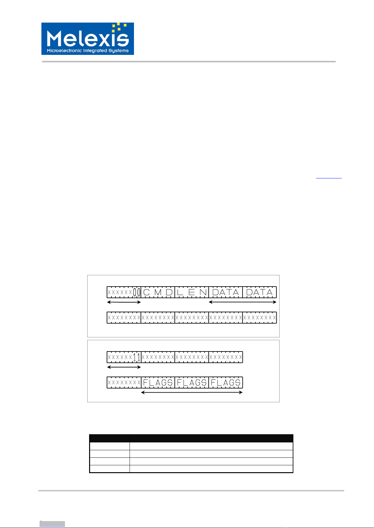
A Control byte is used to specify the communication type and direction (see pictures below):
–00: Send command to the MLX90132
–11: Poll the MLX90132
–10: Read data from the MLX90132
–01: Reset the MLX90132
The SPI_NSS line is used to select a device on the common SPI bus; the SPI_NSS active level is LOW.
When the SPI_NSS line is inactive, all data sent by the application will be ignored and the SPI_MISO line will
be set in high impedance state.
Figure 7: SPI communication, sending command & polling method
The following table shows the meaning of the flags returned by the MLX90132 device.
Bit
Description
[4:7]
RFU, will be set to “0000”
3
Data can be read from MLX90132 when set
2
Data can be sent to MLX90132 when set
[1:0]
MLX Reserved
Table 4: Interpretation of SPI flags
Sending command to the MLX90132
Several data bytes
Control byte
Polling Flags until ready
MOSI
MISO
Polling the MLX90132 until it is ready
Control byte
MOSI
MISO
Downloaded from Arrow.com.Downloaded from Arrow.com.Downloaded from Arrow.com.Downloaded from Arrow.com.Downloaded from Arrow.com.Downloaded from Arrow.com.Downloaded from Arrow.com.Downloaded from Arrow.com.Downloaded from Arrow.com.Downloaded from Arrow.com.

MLX90132
13.56MHz RFID / NFC Transceiver
3901090132 Page 11 of 44 Jan-2014
Rev. 009
Figure 8: SPI communication, reading data from the MLX90132
Data must be sampled by the rising edge of the SPI_SCK signal.
‘Sending’, ‘Polling’ and ‘Reading’ commands must be separated by a high level of the SPI_NSS line.
For example, when the application needs to wait for data from the MLX90132, it sets to low the pin SPI_NSS
and issues a ‘Polling’ command. By keeping the SPI_NSS “low”, the application can continuously read the
Flags waiting for the bit indicating that the MLX90132 is ready (the flags will be automatically updated, no
need to send several polling commands).Then, the application has to set high the pin SPI_NSS to finish the
polling sequence. The application puts low again the pin SPI_NSS to issue a ‘Reading’ command to read
data. When all data is read, the application sets high the pin SPI_NSS to terminate the communication.
The MLX90132 can issue as many 'Polling' commands as necessary.
For example, the application sets low the pin SPI_NSS to issue a 'Polling' commands. If the MLX90132 is not
ready, the application can put high the pin SPI_NSS and continue its operations. Then, as soon as the
application is ready again, it sets low the pin SPI_NSS to issue a 'Polling' commands, to see if the MLX90132
is ready. These operations are not time critical which makes it easy to insert in the application flow.
Figure 9: SPI communication reset the MLX90132
Control byte 0x01 resets the MLX90132 and places the device in Power-up state. A wake-up sequence is
then necessary to start again the communication with the MLX90132.
Warning: The SPI communication is most significant bit (MSB) first.
5.2.2 IRQ mode
When the MLX90132 is configured to use the SPI serial interface, the pin IRQ_OUT is used to give additional
information to the application. When the MLX90132 is ready to send back a reply it sends an Interrupt
request by setting a low level on pin IRQ_OUT, which remains low until the application reads the data. The
application can use the IRQ mode to skip the polling stage.
Several data bytes
Reset MLX90132
Reading data from the MLX90132
Control byte
Control byte
MOSI
MOSI
MISO
MISO
Downloaded from Arrow.com.Downloaded from Arrow.com.Downloaded from Arrow.com.Downloaded from Arrow.com.Downloaded from Arrow.com.Downloaded from Arrow.com.Downloaded from Arrow.com.Downloaded from Arrow.com.Downloaded from Arrow.com.Downloaded from Arrow.com.Downloaded from Arrow.com.

MLX90132
13.56MHz RFID / NFC Transceiver
3901090132 Page 12 of 44 Jan-2014
Rev. 009
6 Commands
6.1 Command format
The structure of the command sent by the application is almost identical to the structure of the answer from
the MLX90132, as shown below:
Command: [CMD] + [LEN] + [DATA]
Answer: [RESPCODE] + [LEN] + [DATA]
-[CMD] = Command (1byte)
-[LEN] = Length including only the field DATA, zero if no data sent (1byte)
-[RESPCODE] = Response code, depends on the command (1byte)
-[DATA] = Data information, depends on the command (0 to 528bytes)
6.2 List of commands
Code
Command
Description
0x01
IDN
Requests short information about device and its FW version
0x02
Protocol Select
Selects communication protocol and specifies some protocol-related
parameters
0x03
Poll field
Returns the current value of the field detector flag (“FieldDet”)
0x04
SendRecv
Sends data using previously selected protocol and receives the response of
the TAG.
0x05
Listen
Listens to the data using previously selected protocol.
0x06
Send
Sends data using previously selected protocol.
0x07
Idle
Switches device into Idle/Sleep/Hibernate mode and specifies which
condition is used to exit from these modes
0x0A
BaudRate
Sets UART baud rate
0x0B
SubFreqRes
Gets the last value of sub-carrier frequency received during ISO/IEC18092
and NFC Tag Type 3 (Felica) communications
0x0D
AC-Filter
Activates/deactivates anti-collision filter
0x55
Echo
MLX90132 replies with an Echo of 0x55 to this command. In this specific
case, the command format is not respected as the data is only 0x55
Other codes
MELEXIS reserved
Table 5: MLX90132 list of commands
Downloaded from Arrow.com.Downloaded from Arrow.com.Downloaded from Arrow.com.Downloaded from Arrow.com.Downloaded from Arrow.com.Downloaded from Arrow.com.Downloaded from Arrow.com.Downloaded from Arrow.com.Downloaded from Arrow.com.Downloaded from Arrow.com.Downloaded from Arrow.com.Downloaded from Arrow.com.

MLX90132
13.56MHz RFID / NFC Transceiver
3901090132 Page 13 of 44 Jan-2014
Rev. 009
6.3 IDN command (0x01)
The IDN command gives information about the MLX90132 and the internal firmware version
IDN0x01
Direction
Data
Comment
Example
MCU –device
01
Command code
0100
00
Length of data
device - MCU
00
Result code
000F4E4643204653324A41535434002ACE:
4E4643204653324A4153543400= Device ID
2ACE= CRC of internal ROM
<Len>
Length of data
<Device ID>
Data in ASCII format
<ROM CRC>
CRC calculated for ROM content
Table 6: “IDN”command description
Note: It takes about 6ms to calculate the CRC for the entire ROM. Application must allow sufficient time
before waiting for an answer for this command.
6.4 Protocol select command (0x02)
The “Protocol Select” command automatically configures the internal registers of the MLX90132 for the best
communication performances. It also prepares the MLX90132 by automatically setting the HF field ON
(except in TAG emulation state). The field will be automatically switched OFF either by sending a “Protocol
select” command with “Field OFF”, or when the MLX90132 returns to “Idle” mode using the “Idle” command
or by selecting TAG emulation.
Protocol Select 0x02
Direction
Data
Comment
Example
MCU –device
02
Command code
Refer to examples in table:
Table 8,below
<Len>
Length of data
<Protocol>
Protocol codes (Reader)
00 = Field OFF
01 = ISO/IEC15693
02 = ISO/IEC14443-A / NFC-A
03 = ISO/IEC14443-B / NFC-B
04 = ISO/IEC18092 (212,424Kbps) / NFC-F
Protocol codes (TAG)
12 = ISO/IEC14443-A/ NFC-A
13 = ISO/IEC14443-B / NFC-B
14 = ISO/IEC18092 (212,424kbps)/ NFC-F
<Parameters>
Depends on protocol selected, refer to Table 8
Device - MCU
00
Result code
0000–Protocol successfully selected
00
Length of data
Device - MCU
82
Error code
8200- Invalid command length
00
Length of data
Device - MCU
83
Error code
8300 - Invalid protocol
00
Length of data
Table 7: “Protocol select”command description
Downloaded from Arrow.com.Downloaded from Arrow.com.Downloaded from Arrow.com.Downloaded from Arrow.com.Downloaded from Arrow.com.Downloaded from Arrow.com.Downloaded from Arrow.com.Downloaded from Arrow.com.Downloaded from Arrow.com.Downloaded from Arrow.com.Downloaded from Arrow.com.Downloaded from Arrow.com.Downloaded from Arrow.com.
MLX90132
13.56MHz RFID / NFC Transceiver
3901090132 Page 14 of 44 Jan-2014
Rev. 009
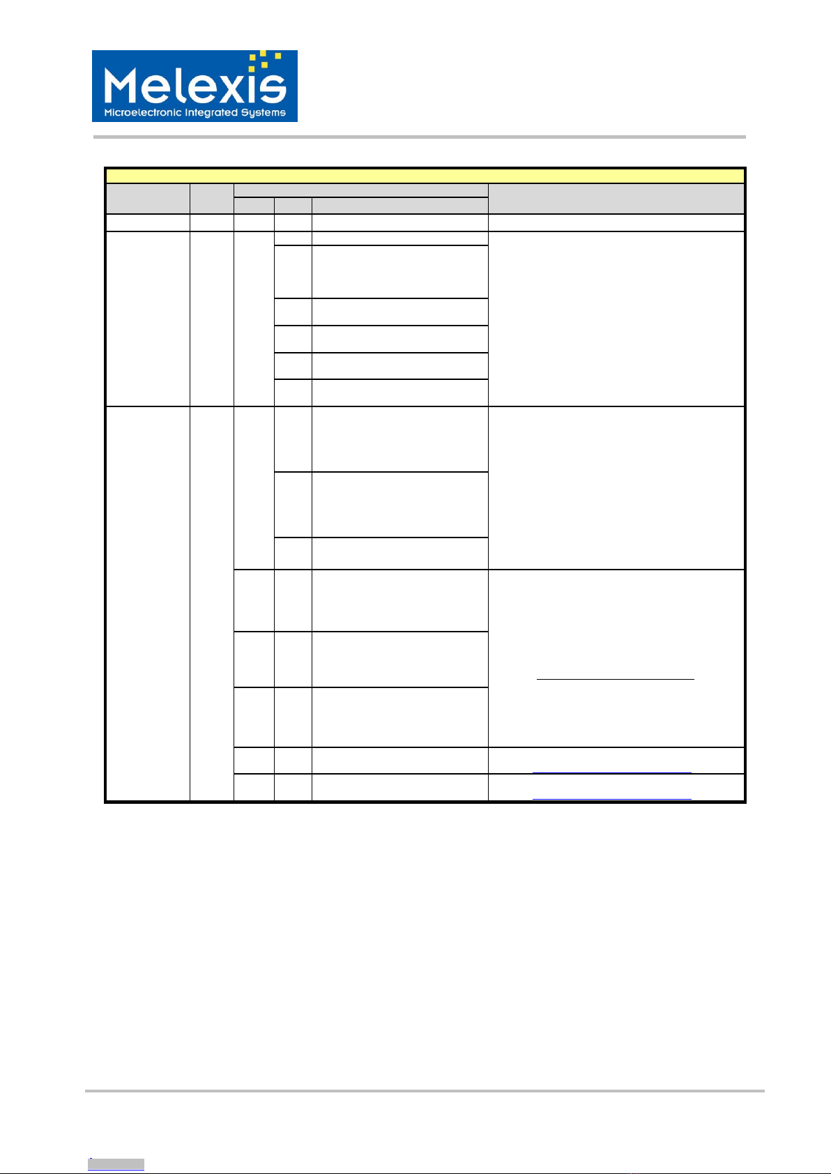
Parameter list for different protocols (Reader)
Protocol
(Reader)
Code
Parameters
Examples of commands
Byte
Bit
Function
Field OFF
00
0
7:0
RFU, set to ‘0’
02020000
ISO15693
01
0
7:6
RFU, set to ‘0’
02020101 –Select ISO/IEC15693, SSC,
26kbps, modulation of 100%, CRC automatically
added
02020107–Select ISO/IEC15693, DSC,
26kbps, modulation 10%, CRC automatically
added
5:4
00 –26kbps
01 –52kbps
10 –6kbps
11 –RFU
3
0 –Respect delay 312us
1 –Wait for SOF
2
0 - 100% modulation
1 –10% modulation
1
0 –Single Sub-Carrier (SSC)
1 –Dual Sub-Carrier (DSC)
0
0 –No CRC added
1 –CRC auto. Added
ISO14443A
NFC-A
02
0
7:6
Transmission data rate
00 –106kbps
01 –212kbps
10 –424kbps
11 –847kbps
02020200 –ISO/IEC14443A, 106kbps
transmission & reception, Frame Delay Time
(FDT) of 86/90µs
5:4
Reception data rate
00 –106Kbps
01 –212Kbps
10 –424Kbps
11 –847Kbps
3:0
RFU, set to ‘0’
1
7:0
PP (max 14, i.e. 0x0E)
Frame Delay Time (FDT) definition: These 3
bytes are optional. When PP, MM and DD are
not specified or set to 0x00, the default value
corresponds to FDT of 86/90us, used during
anti-collision process.
Otherwise, the following formula applies:
][
13.56
32128DD1MM2
FDT
PP
s
If PP is defined, MM must be also set, but DD
still remains optional
2
7:0
MM (max 255, i.e. 0xFF)
3
7:0
DD (max 127, i.e. 0x7F)
4
7:0
NEMD
Related to EMD algorithm, please refer to
chapter Electromagnetic support (EMD)
5
7:0
NEMDRES
Related to EMD algorithm, please refer to
chapter Electromagnetic support (EMD)
Table 8: Parameter values for “Protocol select” command (Reader)
Downloaded from Arrow.com.Downloaded from Arrow.com.Downloaded from Arrow.com.Downloaded from Arrow.com.Downloaded from Arrow.com.Downloaded from Arrow.com.Downloaded from Arrow.com.Downloaded from Arrow.com.Downloaded from Arrow.com.Downloaded from Arrow.com.Downloaded from Arrow.com.Downloaded from Arrow.com.Downloaded from Arrow.com.Downloaded from Arrow.com.

MLX90132
13.56MHz RFID / NFC Transceiver
3901090132 Page 15 of 44 Jan-2014
Rev. 009
Parameter list for different protocols (Reader)
Protocol
(Reader)
Code
Parameters
Examples of commands
Byte
Bit
Function
ISO14443B
NFC-B
03
0
7:6
Transmission data rate
00 –106kbps
01 –212kbps
10 –424kbps
11 –847kbps
02020301 –ISO/IEC14443B, 106kbps
transmission & reception, Frame Waiting Time
(FWT) of 302µs, CRC automatically added
020403010400 –ISO/IEC14443B, 106kbps
transmission & reception, Frame Waiting Time
(FWT) of 4.8ms, CRC automatically added
5:4
Reception data rate
00 –106kbps
01 –212kbps
10 –424kbps
11 –847kbps
3:1
RFU, set to ‘0’
0
0 –No CRC added
1 –CRC auto. added
1
7:0
PP (max 14, i.e. 0x0E)
Frame Waiting Time (FWT) definition:
These 2 bytes are optional. The default value
corresponds to a FWT of 4949ms, answer to
ATTRIB.
][
13.56
32128DD1MM2
FWT
PP
s
If PP is defined, MM must be also set, but DD
still remains optional
2
7:0
MM (max 255, i.e. 0xFF)
3
7:0
DD (max 127, i.e. 0x7F)
5:4
15:0
TTTT
Timing: TR0 = TTTT/13.56 us
Coded with LSB first,
default value 1023 = 0x3FF
6
7:0
YY
Timing: Min_TR1 = 128 * YY / 13.56us.
Default value: 0
7
7:0
ZZ
Timing: Max_TR1 = 128 * ZZ / 13.56us.
Default value:26 , i.e. 0x1A
8
7:0
NEMD
Related to EMD algorithm, please refer to
chapter Electromagnetic support (EMD)
9
7:0
NEMDRES
Related to EMD algorithm, please refer to
chapter Electromagnetic support (EMD)
Table 9: Parameter values for “Protocol select” command (Reader)
Downloaded from Arrow.com.Downloaded from Arrow.com.Downloaded from Arrow.com.Downloaded from Arrow.com.Downloaded from Arrow.com.Downloaded from Arrow.com.Downloaded from Arrow.com.Downloaded from Arrow.com.Downloaded from Arrow.com.Downloaded from Arrow.com.Downloaded from Arrow.com.Downloaded from Arrow.com.Downloaded from Arrow.com.Downloaded from Arrow.com.Downloaded from Arrow.com.

MLX90132
13.56MHz RFID / NFC Transceiver
3901090132 Page 16 of 44 Jan-2014
Rev. 009
Parameter list for different protocols (Reader)
Protocol
(Reader)
Code
Parameters
Examples of commands
Byte
Bit
Function
ISO18092
(212,424Kb)
NFC-F
04
0
7:6
Transmission data rate
00 –RFU
01 –212kbps
10 –424kbps
11 –RFU
02020451 –ISO/IEC18092, 212kbps for
transmission & reception, CRC automatically
added
Parameter ‘Slot counter’ is optional, the
default value 00 (1 slot) will be used, if not
present in the command.
For command SDD (Single Device
Detection), the bit 4 must be set to 0, In this
case RWT is 2.4ms for the 1st slot and 1.2ms
more for each following slot as specified in
protocol ISO18092
5:4
Reception data rate
00 –RFU
01 –212Kbps
10 –424Kbps
11 –RFU
3:1
RFU, set to ‘0’
0
0 –No CRC added
1 –CRC auto. added
1
7:5
RFU, set to ‘0’
4
0 - RWT = 2.4ms
1 –RWT is specified by PP:MM
3:0
Slot counter
0x0 –1 slot
0x1 –2 slots
…
0xF –16 slots
2
7:0
PP (max 14, i.e. 0x0E)
Request Waiting Time (RWT) definition:
These 3 bytes are optional. The default value
corresponds to a RWT of 302µs.
][
13.56
32128DD1MM2
RWT
PP
s
if PP is defined, then MM must be also
defined while, DD remains optional
3
7:0
MM (max 255, i.e. 0xFF)
4
7:0
DD (max 127, i.e. 0x7F)
Table 10: Parameter values for “Protocol select” command (Reader)
Downloaded from Arrow.com.Downloaded from Arrow.com.Downloaded from Arrow.com.Downloaded from Arrow.com.Downloaded from Arrow.com.Downloaded from Arrow.com.Downloaded from Arrow.com.Downloaded from Arrow.com.Downloaded from Arrow.com.Downloaded from Arrow.com.Downloaded from Arrow.com.Downloaded from Arrow.com.Downloaded from Arrow.com.Downloaded from Arrow.com.Downloaded from Arrow.com.Downloaded from Arrow.com.

MLX90132
13.56MHz RFID / NFC Transceiver
3901090132 Page 17 of 44 Jan-2014
Rev. 009
Parameter list for different protocols (TAG Emulation)
Protocol
Code
Parameters
Examples of commands
Comments
Byte
Bit
Function
ISO14443A
NFC-A
12
0
7:6
Transmission data rate
00 –106kbps
01 –212kbps
10..11 - RFU
02021200 –TAG/Card emulation
ISO/IEC14443A, 106kbps for
transmission & reception, return error if no
HF field detected, HFO used as master
clock
0202120A –TAG/Card emulation
ISO/IEC14443A, 106kbps for
transmission & reception, wait for HF field,
CLKREC use as master clock
5:4
Reception data rate
00 –106kbps
01 –212kbps
10..11 –RFU
31)
0 = Return an error, if no field
1 = Wait for field
2
RFU, set to ‘0’
1
0 = HFO
1 = ClkRec
0
RFU, set to ‘0’
ISO14443B
NFC-B
13
0
7:6
Transmission data rate
00 –106kbps
01 –212kbps
10 –424kbps
11 –847kbps
02021300 –TAG/Card emulation
ISO/IEC14443B, 106kbps for
transmission & reception, return error if no
HF field detected, HFO use as master
clock, CRC automatically added
0202130A –TAG/Card emulation
ISO/IEC14443B, 106kbps for
transmission & reception, wait for HF field,
CLKREC use as master clock, CRC
automatically added
5:4
Reception data rate
00 –106kbps
01 –212kbps
10 –424kbps
11 –847kbps
31)
0 = Return an error, if no field
1 = Wait for field
2
RFU, set to ‘0’
1
0 = HFO
1 = ClkRec
0
0 –No CRC added
1 –CRC auto. added
ISO18092
(212,424kb)
NFC-F
14
0
7:4
RFU, set to ‘0’
02021400 –TAG/Card emulation
ISO/IEC18092, return error if no HF field
detected, HFO use as master clock, CRC
automatically added
Note that it is not necessary to select a
data-rate for ISO18092card mode, Data-
rate will be automatically detected and
adjusted during reception (application can
read this information by sending
“SubfreqRecv” command).
31)
0 = Return an error, if no field
1 = Wait for field
2
RFU, set to ‘0’
1
0 = HFO
1 = ClkRec
0
0 –No CRC added
1 –CRC auto. added
Table 11: Parameter values for “Protocol select” command (TAG Emulation)
1) This option will be executed only after a “listen” command has been sent. Please refer to the chapter Listen
command (0x05) for more information.
Downloaded from Arrow.com.Downloaded from Arrow.com.Downloaded from Arrow.com.Downloaded from Arrow.com.Downloaded from Arrow.com.Downloaded from Arrow.com.Downloaded from Arrow.com.Downloaded from Arrow.com.Downloaded from Arrow.com.Downloaded from Arrow.com.Downloaded from Arrow.com.Downloaded from Arrow.com.Downloaded from Arrow.com.Downloaded from Arrow.com.Downloaded from Arrow.com.Downloaded from Arrow.com.Downloaded from Arrow.com.

MLX90132
13.56MHz RFID / NFC Transceiver
3901090132 Page 18 of 44 Jan-2014
Rev. 009
6.5 PollField command (0x03)
The “PollField” command is used to detect the presence of an HF field by monitoring the flag “FieldDet”. This
command returns the current value of the flag “FieldDet”. The parameters <Presc> and <Timer> can also be
used to define a time during which the MLX90132 continuously scans for the presence of HFfield. The
answer to the “PollField” command is available with the flag <FieldDet> updated accordingly, after the
scanning period is terminated.
PollField0x03
Direction
Data
Comment
Example
MCU –device
03
Command code
0300 –Check if Field is ON or OFF
0303010FFF–Wait for field appearance
during(16*256)/13.56=302µs
Parameters Flags, Presc and Timer are optional.
They must be specified if application has to wait
for field appearance or disappearance.
The time to wait is:
]s[
13.56
1)(Timer1)Presc(
imeT
<Len>
Length of data
<Flags>
Timer flag (Optional)
01 –Wait for field appearance
00 –Wait for field disappearance
<Presc>
Timer prescaler (Optional)
<Timer>
Timer time-out (Optional)
Device - MCU
00
Result code
000101 –HF field is detected
01
Length of data
<FieldDet>
[7:1] –RFU
[0] –0 : No HF field detected
1 : HF field detected
Table 12: “PollField”command
Note: When the MLX90132 is selected in reader mode (protocol select command), the HF field will be automatically
turned ON and the flag “FieldDet” will be set to ‘1’ (the MLX90132 detects its own field). Consequently, the PollField
command should be used in Tag/Card Emulation state or in Reader state with the HF field set OFF.
Downloaded from Arrow.com.Downloaded from Arrow.com.Downloaded from Arrow.com.Downloaded from Arrow.com.Downloaded from Arrow.com.Downloaded from Arrow.com.Downloaded from Arrow.com.Downloaded from Arrow.com.Downloaded from Arrow.com.Downloaded from Arrow.com.Downloaded from Arrow.com.Downloaded from Arrow.com.Downloaded from Arrow.com.Downloaded from Arrow.com.Downloaded from Arrow.com.Downloaded from Arrow.com.Downloaded from Arrow.com.Downloaded from Arrow.com.

MLX90132
13.56MHz RFID / NFC Transceiver
3901090132 Page 19 of 44 Jan-2014
Rev. 009
6.6 SendRecv command (0x04)
This command is used to send specific protocol data and receives corresponding answer. Before sending this
command, the application must select a protocol using the Protocol select command. If the response of the
Transponder was successfully received and decoded, the field <Data> will contain additional information
which is protocol specific. This is explained in the Table 14 below.
SendRecv0x04
Direction
Data
Comment
Example
MCU –device
04
Command code
Depends on protocol previously selected!
0403022012–Command “Read single block 12”
(ISO/IEC15693 protocol)
<Len>
Length of data
<Data>
Data to be sent
Device - MCU
<ResultCode>
Result code
8008000000000077CF00 - The response of the
TAG is successfully decoded. This is an example
of response from an ISO15693 TAG.
The result code might contain additional
information on the extended size of received
data. Please refer to paragraph Support of
extended frames below.
<Len>
Length of data
<Data>
Data received. Interpretation depends
on protocol
Device - MCU
<ErrorCode>
Error code
Please refer to the error code table summary in
the chapter List of Error codes
<ErrorBufLen>
Length of Error Buffer stored during
EMD algorithm
<ErrorBuf>
Error Buffer stored during EMD
algorithm
Table 13: “SendRecv" command description
Data format for transmission
Protocol
Explanation
Response example
Comments
ISO15693
Send example
04
03
022000
If length of data is Zero, only EOF will be sent. This can be
used for anti-collision procedure
Command code
Length of entire data field
Data
ISO14443A
NFC-A
Send example
04
07
9370800F8C8E
28
For bit oriented protocol, frames could be split by setting the bit
SplitFrame to one. In this case, the MLX90132 will send the
last byte of the command with none integer number of bits,
according to the field number of significant bits in last byte.
In reception, the MLX90132 expects to receive the complement
(8 –“number of significant bits in last byte”).
This option is used during anti-collision procedure.
Command code
Length of entire data field
Data
Transmission flags:
7 –0 : ISO14443A
1: Topaz format (use EOF instead of P, use
SOF at the beginning of each byte, make
pause between bytes, assume 1st byte as 7-bit)
6 –SplitFrame if set
5 –append CRC if set
4 –Auto. add the parity bit in if set to ‘0’1)
3:0 –number of significant bits in last byte
ISO14443B
NFC-B
Send example
04
03
050000
Command code
Length of entire data field
Data
ISO18092
(212,424Kb)
NFC-F
Send example
04
05
00FFFF0000
Command code
Length of entire data field
Data
Table 14: Parameter values for “SendRecv” command
Downloaded from Arrow.com.Downloaded from Arrow.com.Downloaded from Arrow.com.Downloaded from Arrow.com.Downloaded from Arrow.com.Downloaded from Arrow.com.Downloaded from Arrow.com.Downloaded from Arrow.com.Downloaded from Arrow.com.Downloaded from Arrow.com.Downloaded from Arrow.com.Downloaded from Arrow.com.Downloaded from Arrow.com.Downloaded from Arrow.com.Downloaded from Arrow.com.Downloaded from Arrow.com.Downloaded from Arrow.com.Downloaded from Arrow.com.Downloaded from Arrow.com.

MLX90132
13.56MHz RFID / NFC Transceiver
3901090132 Page 20 of 44 Jan-2014
Rev. 009
1)The process of automatically calculating and adding the parity bit by the MLX90132 can be disabled by
setting the bit 4 of the flags to ‘1’. In this case, the application must add one byte to the data with the most
significant bit corresponding to the parity bit. The other bits of these additional bytes are not considered and
can be set to ‘0’ or ‘1’. The datastream will then look like: <DataByte><Parity><DataByte><Parity>.
Interpretation of <Data> field for different protocols
Protocol
Explanation
Response example
Comments
ISO15693
Response example
80
08
0000000000
77CF
00
000000000077CF- this is a response on
Read Single Block command for Iso15693
TAG. Other fields are added by the device
Result code
Length of entire data field
Data received from TAG
Original (received) value of CRC
7:2 –RFU
1 –CRC error if set
0 –Collision is detected if set
ISO14443A
NFC-A
Response example
80
09
80B30B8DB500
00
00
00
ISO/IEC14443A is bit oriented protocol,
and non-integer amount of bytes can be
received. Number of significant bits in
the 1st byte is the same as indicated in
Send command.
To calculate a position of a collision,
application has to take index of byte first.
Index of bit indicates a position inside
this byte. Note that both indices start from
0 and bit index can be 8, meaning that
collision could also affect the parity bit.
Note that collision information is only
present when protocol ISO/IEC14443A
with a data rate of 106kbps for
transmission and reception is selected.
When others protocols are selected, the
two additional bytes are not transmitted.
Result code
Length of entire data field
Data received from TAG
7 –Collision is detected
6 –RFU
5 –CRC error
4 –parity error
3:0 –shows how many significant bits are there
in the first byte
7:0 –Index of the first byte where collision is
detected
7:4 –RFU
3:0 –Index of the first bit where collision is detected
ISO14443B
NFC-B
Response example
80
0F
5092036A8D00000000007171
3411
00
Result code
Length of entire data field
Data received from TAG
Original (received) value of CRC
7:2 –RFU
1 –CRC error if set
0 –RFU
ISO18092
(212,424Kb)
NFC-F
Response example
80
12
01010105017B06941…93FF
00
801201010105017B06941004014B024F4
993FF00 –typical answer with no error
detected
Result code
Length of entire data field
Data received from TAG
7:2 –RFU
1 –CRC error if set
0 –RFU
Table 15: “SendRecv” command, interpretation of <data> field for different protocol
Downloaded from Arrow.com.Downloaded from Arrow.com.Downloaded from Arrow.com.Downloaded from Arrow.com.Downloaded from Arrow.com.Downloaded from Arrow.com.Downloaded from Arrow.com.Downloaded from Arrow.com.Downloaded from Arrow.com.Downloaded from Arrow.com.Downloaded from Arrow.com.Downloaded from Arrow.com.Downloaded from Arrow.com.Downloaded from Arrow.com.Downloaded from Arrow.com.Downloaded from Arrow.com.Downloaded from Arrow.com.Downloaded from Arrow.com.Downloaded from Arrow.com.Downloaded from Arrow.com.
Other manuals for MLX90132
1
Table of contents
Other Melexis Transceiver manuals


