Memorex MVT2138SM User manual

SERVICE MANUAL
INFORMATION FOR USING THE DECK PARTS
(OVD-5)
DATE OF ISSUE 12/1997
Parts on the deck of our product are very similar as shown below.
Make sure to use the parts listed by Parts No. in the service manual for
the repair, because the deck or your important tape will be damaged.
S/M CODE NO.: OVD5ASM

TABLE OF CONTENTS
1
1
1
2
2
3
3
4
4
5
5
6
6
6
7
7
8
8
9
10
SPRING, MAIN BRAKE ................................................................................................................................................................
SPRING, TENSION ARM 1 ..........................................................................................................................................................
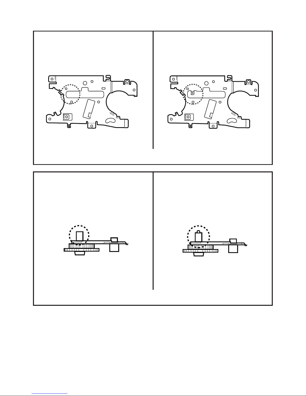
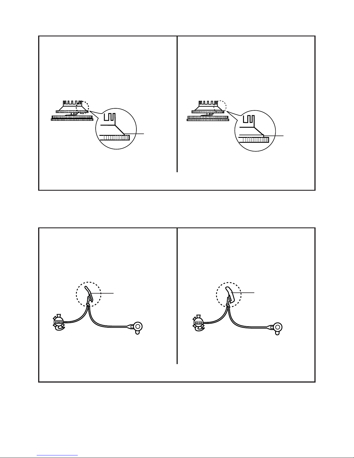
PINCH ROLLER BLOCK ..............................................................................................................................................................
MODE SWITCH ............................................................................................................................................................................
HOLDER, TENSION .....................................................................................................................................................................
CAM, MAIN ...................................................................................................................................................................................
WORM ASS'Y ...............................................................................................................................................................................
MAIN BRAKE T ASS'Y .................................................................................................................................................................
LEVER, MAIN BRAKE ..................................................................................................................................................................
BRACKET, BRAKE .......................................................................................................................................................................
ARM IDLER ASS'Y .......................................................................................................................................................................
CLUTCH GEAR T ASS'Y..............................................................................................................................................................
CLUTCH GEAR S ASS'Y..............................................................................................................................................................
AHC ASS'Y ...................................................................................................................................................................................
CAM PINCH ROLLER...................................................................................................................................................................
P5 ARM ASS'Y .............................................................................................................................................................................
CATCHER P5 2 ............................................................................................................................................................................
MAIN CHASSIS ASS'Y .................................................................................................................................................................
ROD, MAIN ASS'Y........................................................................................................................................................................
CAM, P5........................................................................................................................................................................................
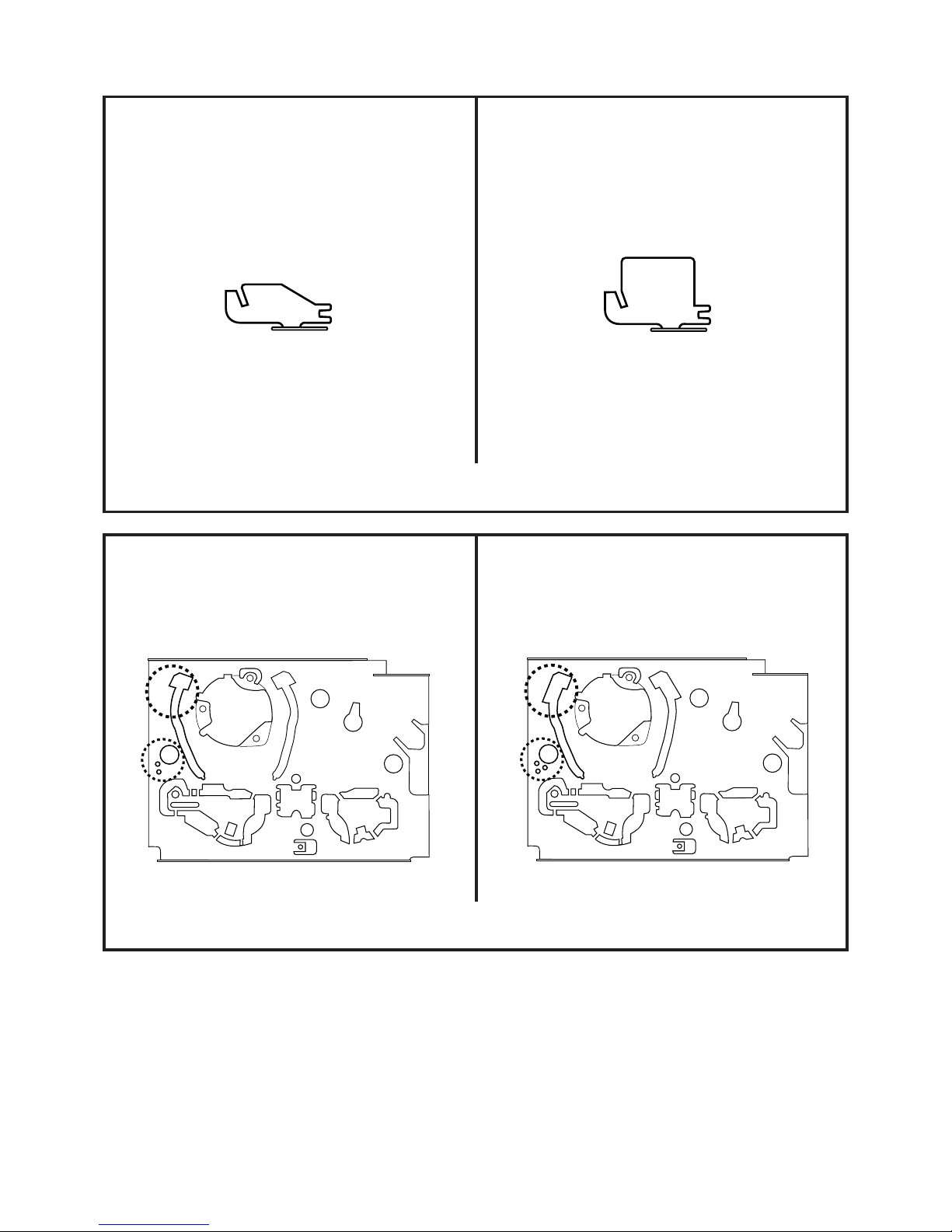
The following parts can not be distinguished by the external appearance.
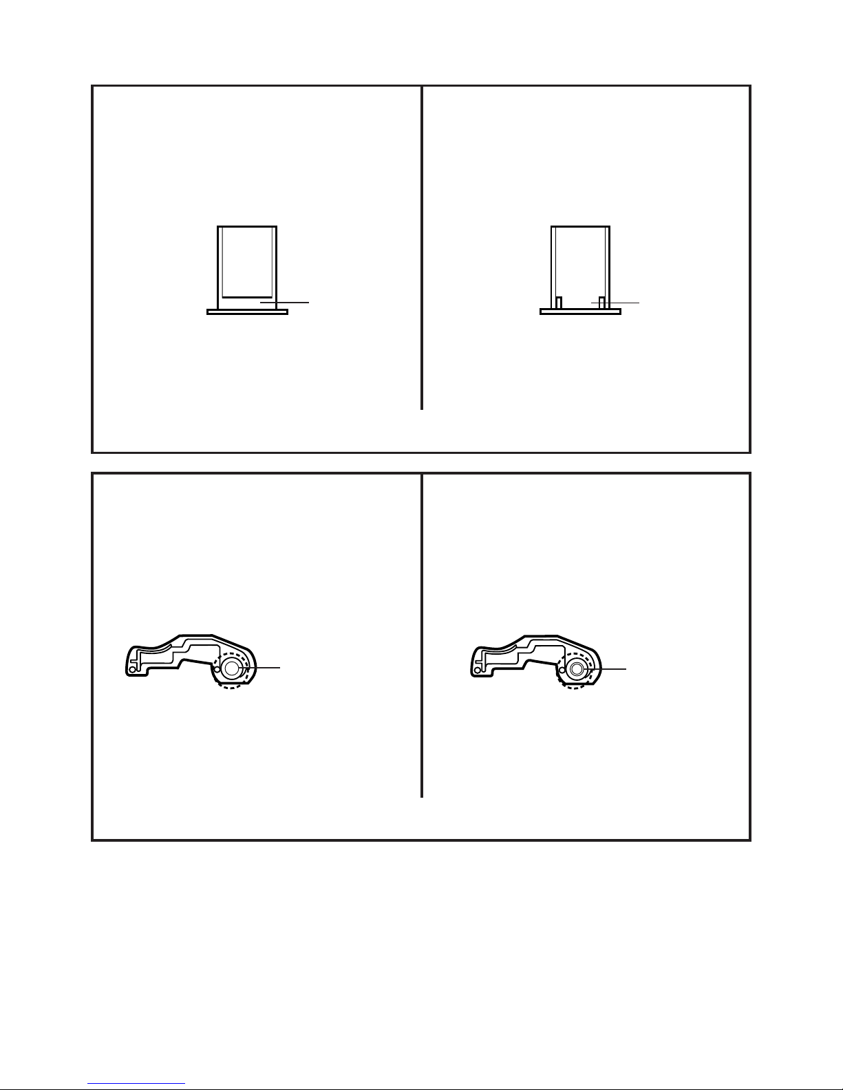
• SPRING, MAIN BRAKE and SPRING, MAIN BRAKE (VP)
• SPRING, TENSION ARM 1 and SPRING, TENSION ARM (1S)
• PINCH ROLLER BLOCK and PINCH ROLLER (PB) BLOCK
So before repairing, please identify each part by referring to the Parts List and Parts No. of Service Manual.
1

NAME: MODE SWITCH
PART NO.: 0520244005 or 0520244007
NAME: MODE SWITCH
PART NO.: 0520244003 or 0520244006
Distinction: You can distinguish by the cut part.
Cut part
2
NAME: HOLDER, TENSION (S)
PART NO.: 85OP400452
NAME: HOLDER, TENSION
PART NO.: 85OP400359
Distinction: You can distinguish by the shape in the dotted circle.

NAME: CAM, MAIN (VP)
PART NO.: 85OP600529
NAME: CAM, MAIN
PART NO.: 85OP600535
Distinction: You can distinguish by the shape in the dotted circle.
NAME: WORM (VP) ASS'Y
PART NO.: 85OA600179
NAME: WORM ASS'Y
PART NO.: 85OA600159
Distinction: You can distinguish by the shape in the dotted circle.
3

NAME: MAIN BRAKE T (VP) ASS'Y
PART NO.: 85OA600178
NAME: MAIN BRAKE T ASS'Y
PART NO.: 85OA600156
Distinction: You can distinguish by the shape.
NAME: LEVER, MAIN BRAKE (VP)
PART NO.: 85OP600530
NAME: LEVER, MAIN BRAKE
PART NO.: 85OP600468
Distinction: You can distinguish by the shape in the dotted circle.
4

NAME: BRACKET, BRAKE (VP)
PART NO.: 85OP600531
NAME: BRACKET, BRAKE
PART NO.: 85OP600471
Distinction: You can distinguish by the shape in the dotted circle.
NAME: ARM IDLER (VP) ASS'Y
PART NO.: 85OA200067
NAME: ARM IDLER ASS'Y
PART NO.: 85OA200065
Distinction: You can distinguish by the shape in the dotted circle.
5

NAME: CLUTCH GEAR T (VP) ASS'Y
PART NO.: 85OA200069
NAME: CLUTCH GEAR S (VP) ASS'Y
PART NO.: 85OA200068
NAME: CLUTCH GEAR S (VPS) ASS'Y
PART NO.: 85OA200071
NAME: CLUTCH GEAR T ASS'Y
PART NO.: 85OA200064
NAME: CLUTCH GEAR S ASS'Y
PART NO.: 85OA200063
NAME: CLUTCH GEAR S (S) ASS'Y
PART NO.: 85OA200070
Distinction: You can distinguish by the existence of the step.
NOTE:
There is no
step. There is a
step.
6
The following parts can't be distinguished by the external appearance.
• CLUTCH GEAR S ASS'Y and CLUTCH GEAR S (S) ASS'Y
• CLUTCH GEAR S (VP) ASS'Y and CLUTCH GEAR S (VPS) ASS'Y
So before repairing, please identify each parts by referring to the Parts List and Parts No. of Service Manual.
NAME: AHC ASS'Y (2)
PART NO.: 85OA500020
MATERIAL COLOR: GRAY
NAME: AHC ASS'Y
PART NO.: 85OA500013
MATERIAL COLOR: WHITE
Distinction: You can distinguish by the material color and shape in the dotted circle.
Width: Approx. 4.5mm
Width: Approx. 2.5mm

Cross Section
NAME: CAM PINCH ROLLER (PB)
PART NO.: 85OP400430
MATERIAL COLOR: GRAY
NAME: CAM PINCH ROLLER
PART NO.: 85OP400433
MATERIAL COLOR: WHITE
Distinction: You can distinguish by the material color and the dent.
NAME: P5 ARM ASS'Y (PB)
PART NO.: 85OA400168
NAME: P5 ARM ASS'Y
PART NO.: 85OA400120
Distinction: You can distinguish by the shape in the dotted circle.
Dent
With a brass sleeve
No Dent
Without a brass sleeve
Cross Section
7

NAME: CATCHER P5 (VP)
PART NO.: 85OP400446
NAME: CATCHER P5 2
PART NO.: 85OP400402
Distinction: You can distinguish by the shape.
NAME: MAIN CHASSIS ASS'Y
PART NO.:
NAME: MAIN CHASSIS ASS'Y
PART NO.:
Distinction: You can distinguish by the shape in the dotted circle.
85OA000173, 85OA000221, 85OA000222,
85OA000229 or 85OA000231 85OA000227, 85OA000226 or 85OA000230
8

9
NAME: ROD, MAIN (S)
PART NO.: 85OA600181
NAME: ROD, MAIN ASS'Y
PART NO.: 85OA600176
NAME: ROD, MAIN (VPS)
PART NO.: 85OP600538
NAME: ROD, MAIN (VP)
PART NO.: 85OP600527
Distinction: You can distinguish by the shape in the dotted circle.
RATCHET PLATE (Back Side) RATCHET PLATE (Back Side)

10
NAME: CAM, P5
PART NO.: 85OP400450
NAME: CAM, P5
PART NO.: 85OP400344
Distinction: You can distinguish by the tooth height of circled section.
All teeth are the same height. Only one tooth is high.

SERVICE MANUAL
Design and specifications are subject to change without notice.
MVT2138
ORIGINAL
MFR’S VERSION C
COLORTELEVISION/VIDEO CASSETTE RECORDER

SERVICING NOTICES ON CHECKING
6. AVOID AN X-RAY1. KEEP THE NOTICES
As for the places which need special attentions,
they are indicated with the labels or seals on the
cabinet, chassis and parts. Make sure to keep the
indications and notices in the operation manual.
3. USE THE DESIGNATED PARTS
5. TAKE CARE TO DEAL WITH THE
CATHODE-RAY TUBE
In the condition that an explosion-proof cathode-
ray tube is set in this equipment, safety is
secured against implosion. However, when
removing it or serving from backward, it is
dangerous to give a shock. Take enough care to
deal with it.
Safety is secured against an X-ray by consider-
ing about the cathode-ray tube and the high
voltage peripheral circuit, etc.
Therefore, when repairing the high voltage pe-
ripheral circuit, use the designated parts and
make sure not modify the circuit.
Repairing except indicates causes rising of high
voltage, and it emits an X-ray from the cathode-
ray tube.
Please include the following informations when you order parts. (Particularly the VERSION LETTER.)
1. MODEL NUMBER and VERSION LETTER
The MODEL NUMBER can be found on the back of each product and the VERSION LETTER can be
found at the end of the SERIAL NUMBER.
2. PART NO. and DESCRIPTION
You can find it in your SERVICE MANUAL.
HOW TO ORDER PARTS
PERFORM A SAFETY CHECK AFTER
SERVICING
7.
Confirm that the screws, parts and wiring which
were removed in order to service are put in the
original positions, or whether there are the
portions which are deteriorated around the
serviced places serviced or not. Check the
insulation between the antenna terminal or
external metal and the AC cord plug blades.
And be sure the safety of that.
(INSULATION CHECK PROCEDURE)
1.
2.
3.
4.
Unplug the plug from the AC outlet.
Remove the antenna terminal on TV and turn
on the TV.
Insulation resistance between the cord plug
terminals and the eternal exposure metal
[Note 2] should be more than 1M ohm by
using the 500V insulation resistance meter
[Note 1].
If the insulation resistance is less than 1M
ohm, the inspection repair should be
required.
[Note 1]
If you have not the 500V insulation
resistance meter, use a Tester.
[Note 2]
External exposure metal: Antenna terminal
Earphone jack
2. AVOID AN ELECTRIC SHOCK
There is a high voltage part inside. Avoid an
electric shock while the electric current is
flowing.
The parts in this equipment have the specific
characters of incombustibility and withstand
voltage for safety. Therefore, the part which is
replaced should be used the part which has
the same character.
Especially as to the important parts for safety
which is indicated in the circuit diagram or the
table of parts as a mark, the designated
parts must be used.
4. PUT PARTS AND WIRES IN THE
ORIGINAL POSITION AFTER
ASSEMBLING OR WIRING
There are parts which use the insulation
material such as a tube or tape for safety, or
which are assembled in the condition that
these do not contact with the printed board.
The inside wiring is designed not to get closer
to the pyrogenic parts and high voltage parts.
Therefore, put these parts in the original
positions.
A1-1

CONTENTS
A2-1
SERVICING NOTICES ON CHECKING .....................................................................
HOW TO ORDER PARTS..........................................................................................
CONTENTS ................................................................................................................
GENERAL SPECIFICATIONS...................................................................................
DISASSEMBLY INSTRUCTIONS
1. REMOVAL OF MECHANICAL PARTS AND P.C. BOARDS ..............................
2. REMOVAL OF DECK PARTS .............................................................................
3. REMOVAL OF ANODE CAP ...............................................................................
KEY TO ABBREVIATIONS ......................................................................................
PREVENTIVE CHECKS AND SERVICE INTERVALS ..............................................
NOTE FOR THE REPLACING OF MEMORY IC .......................................................
DECK PARTS LOCATIONS ......................................................................................
SERVICING FIXTURES AND TOOLS........................................................................
PREPARATION FOR SERVICING .............................................................................
MECHANICAL ADJUSTMENTS ................................................................................
ELECTRICAL ADJUSTMENTS .................................................................................
MAJOR COMPONENTS LOCATION GUIDE ............................................................
BLOCK DIAGRAMS
TV BLOCK DIAGRAM ............................................................................................
Y/C/AUDIO/HEAD AMP..........................................................................................
SYSTEM CONTROL/SERVO.................................................................................
IN/OUT ....................................................................................................................
PRINTED CIRCUIT BOARDS
MAIN/CRT...............................................................................................................
SYSCON .................................................................................................................
OPERATION...........................................................................................................
SCHEMATIC DIAGRAMS
TIMER MICON........................................................................................................
IF/CHROMA............................................................................................................
SOUND AMP ..........................................................................................................
DEFLECTION .........................................................................................................
CRT.........................................................................................................................
POWER (TV) ..........................................................................................................
OPERATION(2) ......................................................................................................
Y/C/AUDIO..............................................................................................................
HEAD AMP .............................................................................................................
IN/OUT ....................................................................................................................
SYSTEM CONTROL/SERVO.................................................................................
POWER (VCR) .......................................................................................................
OPERATION(1) ......................................................................................................
INTERCONNECTION DIAGRAM ...............................................................................
WAVEFORMS ............................................................................................................
MECHANICAL EXPLODED VIEWS ...........................................................................
CHASSIS EXPLODED VIEW.....................................................................................
FRONT LOADING UNIT 15 EXPLODED VIEW .........................................................
MECHANICAL REPLACEMENT PARTS LIST..........................................................
CHASSIS/FRONT LOADING UNIT 15 REPLACEMENT PARTS LIST ....................
ELECTRICAL REPLACEMENT PARTS LIST ...........................................................
A1-1
A1-1
A2-1
A3-1~A3-6
B1-1, B1-2
B2-1~B2-5
B3-1
C1-1, C1-2
C2-1
C3-1
C4-1, C4-2
C5-1
C5-1
D1-1~D1-3
D2-1~D3-1
D4-1, D4-2
E-1, E-2
E-3, E-4
E-5, E-6
E-7, E-8
F-1, F-2
F-3~F-6
F-7, F-8
G-1, G-2
G-3, G-4
G-5, G-6
G-7, G-8
G-9, G-10
G-11, G-12
G-13, G-14
G-15, G-16
G-17, G-18
G-19, G-20
G-21, G-22
G-23, G-24
G-25, G-26
G-27, G-28
H-1~H-4
I-1, I-2
I-3, I-4
I-5
J1-1
J2-1
J3-1~J3-3

GENERAL SPECIFICATIONS
A3-1
G-1.Outline of the Product
13 inch(335.4mmV):Measured diagonally
Color CRT 90 degree deflection
3 -Speed 1/2" Video Cassette Recorder
VHS Recorder/Player
VHS-C Player
G-2.VCR Format
VHS Standard NTSC PAL SECAM PAL-M PAL-N
VHS Hi-Fi Audio System
G-3.Video Recording System :Rotary,slant azimuth two head helical scan system
Luminance Component :FM recording
Chrominance Component :Low frequency converted direct recording
G-4.Broadcasting System US System M
G-5.Color System NTSC PAL SECAM or Monochrome signal
G-6.NTSC Playback(PAL 60Hz) Yes No
G-7.MESECAM Yes No
G-8.Cassette Tape
VHS type video cassette tape Width 12.65mm (1/2 Inch)
VHS-C type video cassette tape Width 12.65mm (1/2 Inch)
G-9.Tape Speed
NTSC or PAL-M PAL or SECAM
SP 33.35 mm/sec SP 23.39 mm/sec
LP 16.67 mm/sec LP 11.69 mm/sec
SLP 11.12 mm/sec
G-10.Recording/Playback Time
NTSC or PAL-M
at SP Mode Max. 210 min. (with T-210 cassette)
at LP Mode Max. 420 min. (with T-210 cassette)
at SLP Mode Max. 630 min. (with T-210 cassette)
PAL or SECAM
at SP Mode Max. 300 min. (with E-300 cassette)
at LP Mode Max. 600 min. (with E-300 cassette)
G-11.Rewind/Fast Forward Time(Approx.)
2' 30" (with T-120 cassette) (with E-180 cassette)
G-12.Search Speed
SP 3 and 5 Times
LP 7 and 9 Times
SLP 9 and 15 Times
G-13.Slow Speed
SP Times
LP Times
SLP Times
G-14.Frame Advance
SP Times
LP Times
SLP Times

GENERAL SPECIFICATIONS
A3-2
G-15.Antenna Input Impedance
VHF/UHF 75 ohm unbalanced
G-16.Tuner and Receiving channel 1Tuner Syatem 2Tuner System
Tuner : Contactless Electric tuner
Oscar(W/O HYPER) Oscar(W/ HYPER) France CATV) Others
Receiving channel
VHF (LOW) 2 ch~ 6 ch
(HIGH) 7 ch~ 13 ch
(CATV) A5 ch~ I ch J ch~ W+29 ch GGG ch~ W+84 ch
UHF 14 ch~ 69 ch
Tuning System
Frequency syn. Voltage syn. Others
G-17.Preset Channel
-- channels
G-18.Intermediate Frequency
Picture(FP) 45.75 MHz MHz MHz
Sound (FS) 41.25 MHz MHz MHz
FP-FS 4.50 MHz MHz MHz
G-19. Stereo/Dual TV Sound
Yes( NICAM GERMAN USA JAPAN) No
G-20.Video Signal
Input Level 1 Vp-p / 75 ohm
Output Level 1 Vp-p / 75 ohm
S/N Ratio 50 dB (Weighted)
Horizontal Resolution at SP Mode 230 Lines
G-21.Audio Signal
Input Level
Line -- dB / -- Kohm
RCA - 8 dB/ 50 Kohm
Output Level
Line -- dB / -- Kohm
RCA - 6 dB/ 1 Kohm
(0dB=0.775 V rms)
S/N Ratio at SP Mode 42 dB
Harmonic Distortion : 1.5 % (1KHz)
Frequency Response : at SP Mode 120 Hz ~ 10 KHz
at LP Mode 120 Hz ~ 6 KHz
at SLP Mode 120 Hz ~ 4 KHz
G-22.Heads Video 2 Rotary Heads
FM Audio Rotary Heads
Audio / Control 1 Stationary Head ( Mono Stereo(L,R) )
Erase 1 Full Track Erase
G-23.Motor: 3 Motors
Tape/Cassette Loading
Cylinder (Direct Drive)
Capstan (Direct Drive)
G-24.Power Source
120 V AC 50Hz AC 60Hz
EXT DC Jack 12 V

GENERAL SPECIFICATIONS
A3-3
G-25.Power Consumption: 88 W at AC 120 V 60 Hz
54 WatDC 12 V
(at TV and VCR ON)
Stand by: 10 W at AC 120 V 60 Hz
Per Year: -- kWh / Year
G-26.Dimensions(Approx.)
365 mm(W) 370 mm(D) 382 mm(H)
G-27.Weight(Approx.) Net : 12.5 Kg ( 27.6 lbs)
Gross: 14.5 Kg ( 32.2 lbs)
G-28.Cabinet Material
Cabinet Front: PS 94HB DECABROM
ABS 94V2 NON-DECA
94V0
Cabinet Rear: PS 94HB DECABROM
ABS 94V2 NON-DECA
94V0
Jack Panel: PS 94HB DECABROM
ABS 94V2 NON-DECA
94V0
G-29.Cassette Loading System: Front Cassette Loading System
Top Loading System
G-30.Tape Counter: Linear Time Tape Counter
G-31.Protector: Power Fuse Dew Sensor
G-32.Regulation
Safety
UL CSA SAA SI CE SEV
BS NF NEMKO FEMKO DEMKO IEC65
SEMKO NZ HOMOLO SABS CNS SISIR
NOM AS3159 DENTORI UNE GOST NONE
Radiation
FCC DOC FTZ PTT CE SEV
SABA SI NF NZ HOMOLO UNE
CNS CISPR13 DENTORI AS/NZS NONE
X-Radiation
PTB DHHS HWC DENTORI NONE
G-33.Temperature
Operation 5 ºC~ 40 ºC
Storage -20 ºC~ 60 ºC
G-34.Operating Humidity Less than 80 %RH
G-35.Clockand Timer
Built-in 1 Month 7 Events Programmable Timer
One Touch Recording : Max Time 5 Hours
Sleep Timer Yes Max 120 Min.( 10 Min. Step) No
On/Off Timer Yes Programs No
Wake Up Timer Yes Programs No
G-36.Timer back up Time
More than 1/12 Minutes (at Power Off Mode)

GENERAL SPECIFICATIONS
A3-4
G-37.Terminals VHF/UHF Antenna Din Type F-Type France Type
Video Input(Front) Phono Jack (RCA ø8.3) BNC
Video Input(Rear) Phono Jack (RCA ø8.3) BNC
Video Output(Rear) Phono Jack (RCA ø8.3) BNC
Audio Input(Front) Phono Jack (RCA ø8.3)
Audio Input(Rear) Phono Jack (RCA ø8.3)
Audio Output(Rear) Phono Jack (RCA ø8.3)
21 Pin DC Jack 12V (Center +)
AC Inlet Ext Speaker
Diversity Ear Phone
Head Phone
G-38.Indicator Power Rec/OTR Play Tape-In Timer Rec
(Red) (Red) (Red)() (Red)
Stand By On Timer Rental Mode(or Clear Picture)
( ) ( )()
One Touch Playback(Button Lights) Charge ( )
Dew Sensor(Play LED Flush) NONE
G-39.On Screen Display
Menu Clock Set( Calendar 12H 24H)
Timer Rec Set Language
Auto Repeat On/Off Area Code
On/Off Timer Set Channel Set
Guide CH Set Picture
ATS System Select
Protect On/Off User Registration
G-CODE(or SHOWVIEW or PLUSCODE)No. Entry
Clock CH
Tape Counter/Memory Tape Speed
Sleep Time EXT.Input
Control Level (Vol,Bright,Cont,Color,Tint,Sharpness)
Control Level (Vol,Bright,Cont,Color,Sharpness)
Play/Stop/FF/Rew/Rec/OTR/T-Rec/Pause
Auto Tracking/Manual Tracking Caption 1/2
Index Sound Mute
Add/Delete Auto Wide On/Off
Wide Select Picture Position
Tone 1/2 Stereo
G-40.OSD Language
Eng Ger Fre Spa Ita Por Jan
OSD Language Setting
Eng Ger Fre Spa Ita Por Jan
Not Applicable
G-41.SpeakerPosition Front Side Bottom
Size 3 inches
Imp 8 ohm x 1 pcs
Power Max 1.0 W (Typical)
10% 0.7 W (Typical)

GENERAL SPECIFICATIONS
A3-5
G-42.EXT Speaker : Yes -- W Imp -- ohm
G-43.Carton
Master Carton: Need No Need
Content: ---- Set
Material: ---- / ---- Corrugated Carton
Dimensions: ---- mm(W) ---- mm(D) ---- mm(H)
Description of Origin Yes No
Gift Box
Material AB Double/Brown Corrugated Carton ( with Photo Label)
AB Double/White Corrugated Carton ( with Photo Label)
AB Double Full Color Carton W/Photo
Dimensions: 447 mm(W) 423 mm(D) 443 mm(H)
Design: As Per BUYER 's
Description of Origin: Yes No
Drop Test Natural Dropping At 1 Corner / 3 Edges / 6 Surfaces
Height 25cm 31cm 46cm 62cm 80cm
Container Stuffing: 700 Sets / 40' container
G-44.Accessories
Channel Film Dew Caution Sheet
Owner's Manual ( W/Guarantee Card) [English/French]
Remote Control Unit AC Plug Adaptor
Rod Antenna ( One Pole Two Pole/ F-Type DIN Type France Type)
Loop Antenna( F-Type DIN Type France Type)
U/V Mixer Quick Set-up Sheet
DC Car Cord (Center+) Battery (UM- 4 x 2 )
Guarantee Card AC Cord
Warning Sheet AV Cord (2Pin-1Pin)
Circuit Diagram Registration Card
Antenna Change Plug PTB Sheet
Service Facility List 300 ohm to 75 ohm Antenna Plug
Euro Warranty Information Sheet
G-45.Other Features
Auto Head Cleaning Index Search
Auto Tracking Auto Search
CH Auto Set-Up/Auto Clock ATS
VIDEO PLUS+(SHOWVIEW,G-CODE) PDC
HQ (VHS Standard High Quality) VPS
Auto Power On, Auto Play, Auto Rewind, Auto Eject,Auto Repeat System
Forward / Reverse Picture Search SQPB
One Touch Playback CATV(181CH)
Auto CH Memory Anti-Theft
Just Clock Function Rental Mode
Closed Caption Fastext
Toptext Unitext
TV Auto Shutt off Function TV Monitor
NTSC Playback PAL TV (PAL 60Hz) TV/Rec Monitor
One Touch Automatic Channel Programing

GENERAL SPECIFICATIONS
A3-6
G-46.Switch
Front Power(Tact) Channel Up Volume Up
Play Channel Down Volume Down
Pause/Still F.FWD/Cue Rew/Rev
System Select Eject/Stop Rec/OTR
One Touch Playback Main Power SW
Rear Color On/Off (SECAM only) Degauss
Main Power SW AC/DC
G-47.Magnetic Field
BV : +0.45G BV : +0.35G BV : +0.25G
BH : 0.18G BH : 0.30G BH : 0.30G
BV : -0.15G BV : -0.25G BV : -0.50G
BH : 0.15G BH : 0.15G BH : 0.30G
G-48.Remote Control Unit: RC-BH
Power Source: D.C 3 V Battery UM - 4 x 2
0 Power Prog.CFM
1 Rec/OTR Enter
2 Play Set +
3 F.Fwd Set -
4 Rew Auto Ch Memory
5 Pause/Still Delete
6 Stop Add
7 Eject Tracking Auto
8 Slow Tracking Up
9 Clock/Counter Tracking Down
10 Counter Memory Call
11 Counter Reset TV/Caption/Text
12 TV/VCR Caption On/Off
Ch Up Speed Ch.1/2
Ch Down Index Caption 1/2
Volume Up Sleep Timer Mute
Volume Down Repeat Preset (Ch Set)
Quick View Bar Select AFT
Clock/Prog Normalize Select
Menu Cancel Timer Rec
Search Up TV Monitor Ch.Set
Search Down Mute/Normal Daily
Fine Tuning Up/Tracking Up Rental Mode
Fine Tuning Down/Tracking Down Input Select
Tuning Select (Auto Search On/Off) Once
One Touch Playback VIDEO PLUS+ (SHOWVIEW,G-CODE)
Weekly F/T/B Text/Mix/TV
Red Cyan Yellow
Green Status Reset
This manual suits for next models
1
Table of contents
Other Memorex TV VCR Combo manuals

Memorex
Memorex MVT2137 User manual

Memorex
Memorex MVT2194 User manual

Memorex
Memorex MVT2139 A Series User manual

Memorex
Memorex MVT2195B User manual

Memorex
Memorex MVT2197 A Series User manual

Memorex
Memorex MVT2090 User manual

Memorex
Memorex MVT2138 User manual

Memorex
Memorex MVT2135B D Series User manual

Memorex
Memorex MVT2090 User manual

Memorex
Memorex MVT2195 User manual