Memotech Limited RS232 User manual

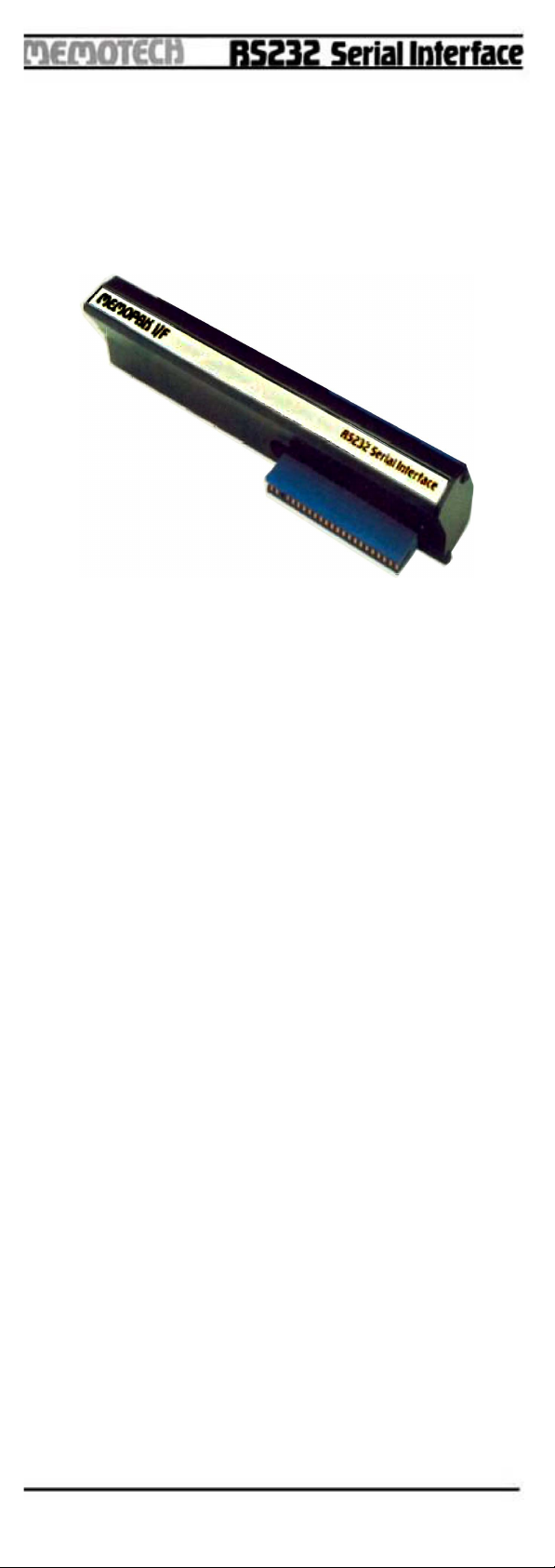
MEMOTECH RS232 Interface
INSTRUCTION MANUAL
TABLE OF CONTENTS
Introduction 1
Basic mode 1
Terminal mode 3
Direct mode 5
Handsha ing 6
Setting up RS232 and Memotext 6
Interface Signal Description 7
Control register 10
Command register 11
Status register 11
ASCII/ZX Character conversions 15

INTRODUCTION
The MEMOTECH RS232 Interface can be used in three
modes.
1. BASIC
2. TERMINAL
3. DIRECT
The BASIC and TERMINAL mode have resident software in
the interface pack and it is recommended that one of
these modes is used whenever possible. If however
neither of these modes is applicable, the interface
registers may be accessed directly.
To achieve any serial communication with another RS232
device you must ensure that:
a A suitable cable has been connected.
b The correct BAUD rate, STOP BITS and PARITY are
selected
c A suitable handshake is used if receiving at high baud
rates
The interface is programmed to transmit and receive at 300
BAUD with no stop bits and no parity. If different settings
are required, then a routine is provided to alter them.
ecause of the peculiar timing of the ZX81 it may be found
that to ensure accurate tranceiving of information a
handshaking arrangement should be adopted depending
on the nature of the receiver and transmitter. See the
section on handshaking for details.
All transmissions take place in ASCII and translation takes
place automatically.
1. BASIC
The ASIC mode allows a ASIC programme to
communicate conveniently with the RS232 interface.
Several routines are provided and they are accessed by
calling appropriate USR routines. To initialise the RS232,
a call to USR 10900 will set up the baud rate parity and
stop bits according to the contents of P$. It will also
execute a dummy read of the read register.
If P$ is not present then the default conditions will be
assumed. i.e.
RAND USR 10900 will set the RS232 to
No parity
1 stop bit
300 Baud
-Page 1-

If P$ is present, it is assumed that it contains an image of the
command and control
registers in the form
LET P$ = "control, command"
Refer to pages 13 & 14 to see the effect of these registers.
e.g.
10 LET P$ = "10011110,00001000"
20 RAND USR 10900
30 CLEAR
sets the RS232 to :
Parity Disabled
2 stop bits
9600 Baud
After initialising the RS232 in this way, P$ may be cleared
since it is no longer needed. It is not normally necessary
to clear P$ except in the case of using the
TERMINAL mode when no exlra memory is attached. In this
case the terminal needs the space and will give an error
message if P$ is not cleared .
Having initialised the RS232, a range of software utility
programmes are available each of which is invoked by
calling a USR routine. These routines return the number
of characters transmitted or received except for
transmitting the display file.
Receiving into R$ is either terminated when R$ becomes full
or when end of transmission characters are received (i.e.
ETX ASCII 3 or ETB ASCII 7, these termination
characters are stored in R$)
DESCRIPTION USR ADDRESS
Transmit the contents of T$
a. unadorned transmission 10890
b. converting ZX code to ASCII 10895
(If an attempt is made to transmit a ZX character which
cannot be converted to an ASCII character, a null
character will be transmitted.)
-Page 2-

Transmit the display file
a. without LF at end of line 11504
b. with LF at end of line 11500
Fetch a string of characters into R$
a. converting to ZX code 10885
b. no conversion 10880
(If the ZX81 receives a character that it cannot convert to ZX
code, an inverse space will be stored in R$)
Example of transmitting a string in T$
10 REM INITIALISE RS232
20 RAND USR 10900
30 INPUT T$
40 REM TRANSMIT T$ CONVERTING TO ASCII
50 RAND USR 10895
60 GOTO 30
Example of transmitting the display file
10 RAND USR 10900
20 PRINT '"THE QUICK ROWN FOX"
30 PRINT "JUMPED OVER THE LAZY DOG "
40 RAND USR 11500
Example of receiving characters into R$.
10 RAND USR 10900
20 DIM R$ (20)
30 LET Y= USR 10885
50 PRINT R$
2. TERMINAL
With the RS232 pack attached, the ZX81 can be used as a
terminal. The baud rate parity and stop bits are set up as
in the ASIC mode and then the terminal is invoked by
calfing USR 10937. The terminal rnay take a few seconds
to clear the display file and then a cursor will appear in the
top left (home) position.
-Page 3-

e.g.
LET P$ = "00011110,00001000"
RAND USR 10900
CLEAR
RAND USR 10937
The keyboard can now generate all ASCII codes. The
terminal is initially in a full duplex mode so that anything
typed at the keyboard will be transmitted via the RS232
but will not appear on the screen, and any valid character
received by the RS232 will be printed on the screen. If the
ZX81 cannot recognize a character it will print a question
mark. If it receives a cursor control such as cursor left or
home cursor it will act accordingly.
To change to half duplex mode, type shift F (FAST). Now any
characters typed will appear on the screen as well as
being transmitted. Typing shift F again will reset the
terminal to full duplex. The following table describes the
effect of other keys.
Key Transmitte
d to
RS232
Printed on
screen
Comments
Stop - Scrolls 2 lines if
cursor is at
bottom of screen
Returns to ASIC
Edit ^L (12) Clear screen
and home
cursor
Rubout DEL (127) inverted*
LLIST Display file Cursor
disappears
Input is temporarily
suspended whilst the
contents of the display
file are transmitted. A
CR is transmitted at
the end of each line.
if the auto line feed is
on then a line feed
character is also
transmitted .
Shift T The following
character is
interpreted as a
control character and
that character is
transmitted
Shift 5 ^H (8) ackspace
Shift 6 ^J (10) linefeed
Shift 7 ^K (11) Cursor up
Shift 8 ^Y (25) Cursor forwards
Shift H ^Z (26) Home Cursor
-Page 4-
TOGGLES
Key Transmitted
to RS232
Printed on
screen
Comments
LPRINT Anything printed on
the screen is echoed
to a Sinclair or
Centronics printer
FAST HALF/FULL DUPLEX
Shift
NEWLINE
(AutoIine
feed)
Toggles whether
(AutoIinefeed)
NEWLINE
generates a CR or
CR and LF
GRAPH Upper or Lower case
HOW RECEIVED CONTROL CHARACTERS AFFECT THE ZX81
ASC CONTROL NAME DISCRIPTION
8H S ack Space
10 J LF Linefeed
11 K UP Cursor Up
12 L CLR Clear Screen and Home Cursor
13 M CR Carriage Return Auto Linefeed if on
25 Y FWD Cursor Forward
26 Z HME Cursor to top left
3. DIRECT CONTROL
To test if the transmitter is empty USR 11679 will return
nonzero if empty.
To test if the receiver is full USR 11436 will return nonzero if
full.
To read the receive register (toggles handshake) USR 11445
will return the value.
e.g. Let y = USR 11445
LOCATIONS OF MEMORY MAPPED REGISTERS
WRITE REGISTER 12040
READ REGISTER 12044
WRITE STATUS 12041
READ STATUS 12045
WRITE COMMAND 12042
READ COMMAND 12046
WRITE CONTROL 12043
READ CONTROL 12047
-Page 5-

SETTING UP THE RS232 I/F AND MEMOTEXT
1. Switch off Memotext so that ZX81 powers up into
Basic.
2. Set up RS232 parameters (Baud Rate etc.) as in the
Basic mode.
3. Switch on Memotext.
4. Press NEW then NEWLINE.
5. Memotext will ask " RS232/CENT? "
6. Type R for RS232, then continue with Memotext
Boo let.
HANDSHAKE
If no handshake lines are connected, it is assumed that
devices are free to transmit and receive.
The memotech RS232 caters for two modes of transmit
handshake and two modes of receive handshake.
RECEIVE
Output pin 20 (DTR or DTREADY) The link at the back of the
RS232 determines whether pin 20 is DTR or DTREADY. If
the link is positioned on the 2 pins nearest to the center of
the case, pin 20 will become DTREADY. If it is positioned
on the 2 outer pins it will be DTR.
In either case, pin 20 is used to prohibit any further
transmission to the Memotech RS232 when it is driven
LOW.
/DTR mode: pin 20 goes low after receiving the entire byte.
/DTREADY: pin20 goes low on receiving the start of the byte.
The use of these two modes will be determined by whether
or not the transmitting device aborts the byte being
transmitted when it receives the stop transmission signal
from the receiving device.
TRANSMIT
Input pins 5 (/CTS) and 6 (/DSR)
/CTS (input pin 5) is a hardware transmit inhibit. If this pin is
driven low by the receiving device, the current byte being
transmitted will be aborted and will be retransmitted when
the pin goes high again.
-Page 6-
/DSR (input pin 6) is a software transmit inhib. This signal is
used by the resident software and is monitored after a
byte has been transmitted to ensure that the byte is not
aborted.
INTERFACE SIGNAL DESCRIPTION
/RES (Reset) During system inilialization a low on the /RES
input will cause internal registers to be cleared .
Ø2 (Input Clock) The input clock is the system Ø2 clock and
is used to trigger all data transfers between the system
microprocessor and the SY6551.
R/W (Read/Write) The R/W is generated by the
microprocessor and is used to control the direction of
data transfers. A high on the R/W pin allows the
processor to read the data supplied by the SY6551. A
low on th R/W pin allows a write to the SY6551.
/IRQ (interrupt Request)
The /IRQ pin is an interrupt signal from the interrupt control
logic. It is an open drain output, permitting several
devices to be connected to the common /IRQ
microprocessor input. Normally a high level, /IRQ goes
low when an interrupt occurs.
DB0-DB7 (Data Bus)
The DB0-DB7 pins are the eight data lines used for
transfer of data between the processor and the
SY6551. These lines are bi-directional and are normally
highimpedance except during Read cycles when
selected.
CS0, /CS1 (Chip Selects)
The two chip select inputs are normally connected to
the processor address lines either directly or
throughdecoders. The SY6551 is selected when CSO
is high and /CS1 is low.
RS0, RS1 (Register Selects)
The two register select lines are normally connected to
the processor address lines to allow the processor to
select the various SY6551 internal registers. The
following table indicates the internal register select
coding:
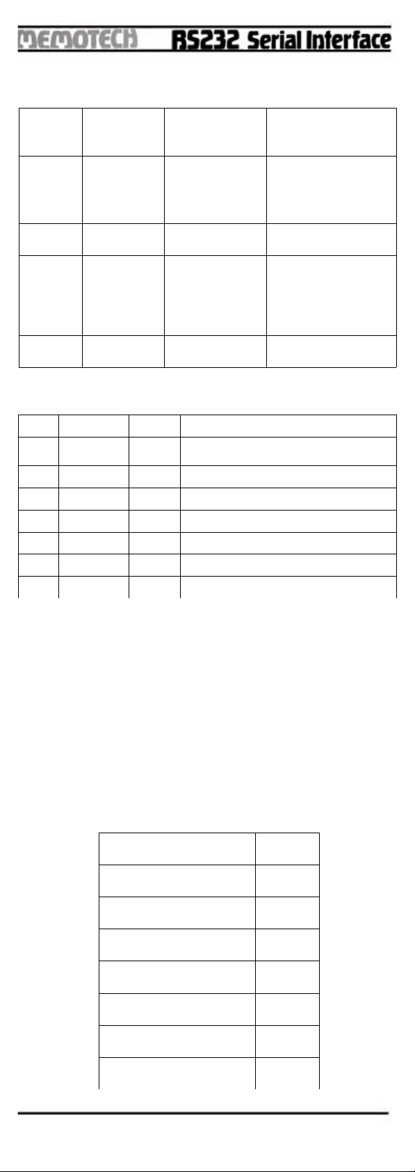
RS1 RS0 Write Read
00 Transmit Data Register Receive Data Register
01 Programmed Reset
(Data is "Don't Care")
Status Register
10 Command Register
11 Control Register.
-Page 7-
The table shows that only the Command and Control
registers are read/write.
The Programmed Reset operation does not cause any data
transfers but is used to clear the SY6551 registers. The
Programmed Reset is slightly different from the Hardware
Reset (RES) and these differences are described in the
individual register definitions.
ACIA/MODEM INTERFACE SIGNAL DESCRIPTION
XTAL1, XTAL2 (Crystal Pins)
These pins are normally directly connected to the external
crystal (1.8432 MHz) used to derive the various baud
rates. Alternatively, an externally generated clock may be
used to drive the XTAL1 pin, in which case the XTAL2 pin
must float.
TxD (Transmit Data)
The TxD output line is used to transfer serial NRZ (non-
return-to-zero) data to the modem. The LS (least
significant bit) of the Transmit Data Register is the first
data bit transmitted and the rate of data transmission is
determined by the baud rate selected.
RxD (Receive Data)
The RxD input line is used to transfer serial NRZ data into
the ACIA from the modem, LS first. The receiver data
rate is either the programmed baud rate or the rate of an
externally generated receiver clock. This selection is
made by programming the Control Register.
RxC (Receive Cloc )
The RxC is a bi-directional pin which serves as either the
receiver 16x clock input or the receiver 16x clock output. The
latter mode results if the internal baud rate generator is
selected for receiver clocking.
/RTS (Request to Send)
The /RTS output pin is used to control the modem from the
processor. The state of the /RTS pin is determined by the
contents of the Command Register.
/CTS (Clear to Send)
The /CTS input pin is used to control the transmitter
operation. The enable state is with /CTS low. The
transmitter is automatically disabled if /CTS is high.
/DTR (Data Terminal Ready)
This output pin is used to indicate the status of the SY6551
to the modem. A low on /DTR indicates the SY6551 is
enabled and a high indicates it is disabled. The processor
controls this pin via bit O of the Command Register.
-Page 8-
/DSR (Data Set Ready)
The DSR input pin is used to indicate to the SY6551 the
status of the modem. A low indicates the « ready »state
and a high, « not-readyg ». /DSR is a high-impedance
input and must not be a no-connect. If unused, it should
be driven high or low, but not switched .
Note: If Command Register it 0 = 1 and a change of state
on /DSR occurs, /IRQ will be set, and Status Register it
6 will reflect the new level. The state of /DSR does not
affect either Transmitter or Receiver operation.
/DCD (Data Carrier Detect)
The DCD input pin is used to indicate to the SY6551 the
status of the carrier-detect output of the modem. A low
indicates that the modem carrier sig al is present and a
high, that it is not. /DCD, like /DSR, is a highimpedance
input and must not be a noconnect.
Note: If Command Register it 0 = 1 and a change of state
on /DCD occurs, IRQ will be set, and Status Register it 5
will reflect the new level. The state of DCD does not affect
Transmitter operation, but must be low for the Receiver to
operate.
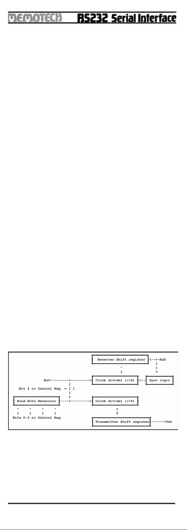
INTERNAL ORGANIZATION
The Transmitter/Receiver sections of the SY6551 are
depicted by the block diagram in Figure 1.
Figure 1. Transmitter/Receiver Clock Circuits
its 0-3 of the Control Register select the divisor used to
generate the baud rate for the Transmitter. If the Receiver
clock is to use the same baud rate as the Transmitter,
then RxC becomes an output pin and can be used to
slave other circuits to the SY6551 .
-Page 9-

Figure 2. Block Diagram
CONTROL REGISTER
The Control Register is used to select the desired mode for
the SY6551. The word length, number of stop bits, and
clock controls are alI determined by the Control Register,
which is depicted in Figure 3.
Figure 3. Control Register Format
7 6 5 4 3 2 1 0
HARDWARE RESET 0 0 0 0 0 0 0 0
PROGRAM RESET - - - - - - - -
-Page 10-
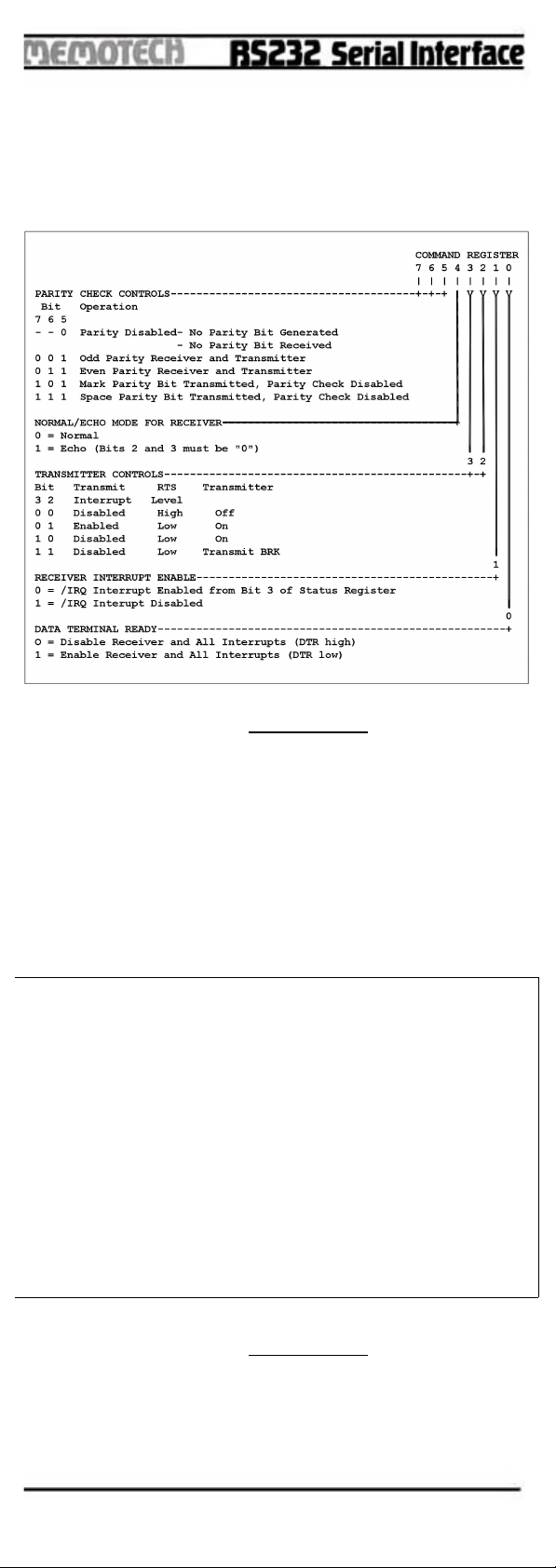
COMMAND REGISTER
The Command Register is used to control Specific
Transmit/Receive functions and is shown in Figure 4.
Figure 4. Command Register Format
7 6 5 4 3 2 1 0
HARDWARE RESET 0 0 0 0 0 0 0 0
PROGRAM RESET - - - 0 0 0 0 0
STATUS REGISTER
The Status Register is used to indicate to the processor the
status of various SY6551 functions and is outlined in
Figure 5.
Figure 5. Status Register Format
7 6 5 4 3 2 1 0
HARDWARE RESET 0 - - 1 0 0 0 0
PROGRAM RESET - - - - - - - -
-Page 11-
7 6 5 4 3 2 1 0
| | | | | | | | STATUS SET BY CLEARED BY
| | | | | | | +----Parity Error* 0 No Error Self Clearing**
| | | | | | | 1 Error
| | | | | | +------Framing Error* 0 No Error Self Clearing**
| | | | | | 1 Error
| | | | | +--------Overrun* 0 No Error Self Clearing**
| | | | | 1 Error
| | | | +----------Receive Data 0 Not Full Read Receive Data
| | | | Register Full 1 Full Register
| | | +------------Transmit Data 0 Not empty Write Transmit Data
| | | Register Empty 1 Empty Register
| | +--------------/DCD 0 /DCD Low Not Resettable
Reflects
| | 1 /DCD High /DCD State
| +----------------/DSR 0 /DSR Low Not Resettable
Reflects
| 1 /DSR High /DSR State
+------------------IRQ 0 No Interrupt Read Status Register
1 Interrupt
* no interupt generated for these conditions
** cleared automatically after a read of RDR and the next error free
receipt of data

TRANSMIT AND RECEIVE DATA REGISTERS
These registers are used as temporary data storage for the
6551 Transmit and Receive circuits. The Transmit Data
Register is characterized as follows:
- it 0 is the leading bit to be transmitted.
- Unused data bits are the high-order bits and are "don't
care" for transmission .
The Receive Data Register is characterized in a similar
fashion:
- it 0 is the leading bit received.
- Unused data bits are the high-order bits and are "0" for the
receiver.
- Parity bits are not contained in the Receive Data Registers
but are stripped-off after being used for external parity
checking. Parity and all unused high-order bits are "0".
Figure 6 illustrates a single transmitted or received data
word, for the example of 8 data bits, parity, and 1 stop bit.
Figure . Serial Data Stream Example
-Page 12-
"MARK" "MARK"
------ ...+----------
|___| 0 | 1 | 2 | 3 | 4 | 5 | 6 | 7 | P| ...
DATA BITS
STOP BIT
START PARITY
MEMOTECH RS232
INTERFACE CONNECTOR
Plugs into Printer
Figure 7. 2 way (13 + 13), Unshrouded Header Plug
25 Way D type Socket
3M Part No 3635
ZX81 REAR CONNECTOR
(see ZX81 ASIC Handbook)
-Page 13-
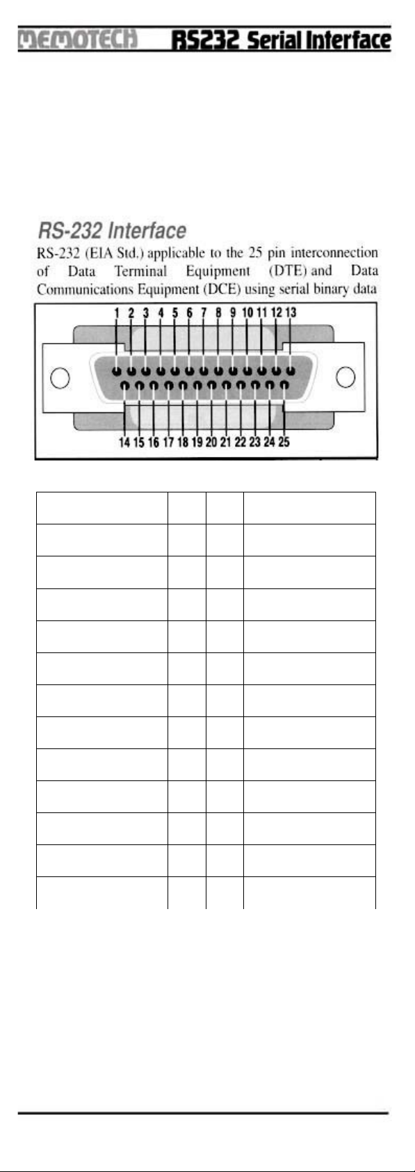
GND 1 14 NC
TXD 2 15 NC
RXD 3 16 NC
/RTS 4 17 RXC
/CTS 5 18 NC
/DSR 6 19 NC
GND 7 20 /DT READY/DTR
/DCD 8 21 NC
NC 9 22 NC
NC 10 23 NC
NC 11 24 NC
NC 12 25 NC
NC 13 26 NC
RS232 CA LE CONNECTOR
Plugs into Memopak RS232 Interface
26 Way low-profile Header Socket
3M Part No: 3399
OCRed text file from http:\\zx81.nl
PDF from ZX81 comunity. © 2019
-Page 14-
14 25
1 13
| |
| | <-------Pin 1 Connector
| |
| |
| |
| |
| | 26 WAY RIBBON CABLE
| |
| |
26 14
13 1

I/F ASCII CHARACTERS :
-Page 15-

-Page 16-

-Page 17-
-Page 18-
Table of contents


