Chinowing T40 User manual
www.chinowing.com
1
User Manual
T40 Portable Ground Control Station
(July, 2021)
V 1.0.3 video&data&RC link V21 V30 V40

www.chinowing.com
2
目录
1. Disclaimer............................................................................................. 4
2. Product Precautions............................................................................. 4
2.1 Installation Note......................................................................... 5
2.2 Precautions for Use.................................................................... 5
3. Product Introduction............................................................................ 6
4. Item List................................................................................................ 6
4.1 V21 Version.................................................................................6
4.2 V30 Version.................................................................................8
4.3 V40 Version.................................................................................9
5. Product Instruction.............................................................................11
5.1 T40 GCS.....................................................................................11
5.2 V21 Receiver............................................................................. 12
5.3 V30 Receiver............................................................................. 15
5.4 V40 Receiver............................................................................. 18
6. T40 Secondary Screen Instruction......................................................21
6.1 Secondary-Screen Touch Calibration....................................... 22
6.2 Split Screen Settings................................................................. 22
7. T40 GCS Operation............................................................................. 23
7.1 Remote Control Power-on and Power-Off...............................23
7.2 Indicator Instruction of GCS and Receiver............................... 24
8. T40 GCS <Parameters Setting Software> Operation......................... 28
8.1 <Parameters Setting Software> Instruction.............................28
8.2 Channel Monitoring and Calibration........................................ 28
8.3 Channel Configuration..............................................................29
8.4 Key Setting................................................................................33
8.5 Failsafe Setting......................................................................... 35
8.6 External SBUS Input..................................................................37
8.7 Other Settings...........................................................................37
8.8 T40 Alarm Instruction...............................................................38
8.9 T40 Charging Instruction.......................................................... 38
9. T40 GCS External Ports Instruction................................................ 39
9.1 COM Port Connection Instruction............................................ 39
9.2 Aviation Plug Output Instruction..............................................40
10. V21 Video Link Module Operation and Use..................................41

www.chinowing.com
3
10.1 V21 Connection Instruction....................................................41
10.2 V21 Serial Port Use................................................................. 42
10.3 V21 LAN Port Use................................................................... 43
10.4 V21 Video&Data Link Quick Reset and Configuration........... 45
11. V30 Video Link Module Operation and Use..................................50
11.1 V30 Video Link Connection Instruction.................................. 50
11.2 Display the Video in Mission Planner..................................... 52
11.3 Display Image in QGC Software..............................................54
11.4 V30 Parameters Configuration...............................................56
11.5 Supporting Instruction Sheet................................................. 57
12. V40 Video Link Module Operation and Use..................................60
12.1 V40 Connection Instruction....................................................60
12.2 Serial Port Configuration Instruction......................................61
12.3 Serial Port Configuration Modification Instructions.............. 63
12.4 V40 HDMI Operation Instruction........................................... 67
12.5 Airborne LAN Port Operation................................................. 69
13. Video Link Parameters..................................................................... 71
13.1 V40 Video Link Parameters.................................................... 71
13.2 V21 Video Link Parameters.................................................... 72
13.3 V30 Video Link Parameters.................................................... 73
14. HID Controller Instruction................................................................ 74
15. Firmware Upgrading Operation Steps............................................. 77
15.1 T40 GCS Firmware Upgrade................................................... 77
15.2 V21 Receiver Firmware Upgrade............................................80
16. Common Questions.......................................................................... 81
17. T40 Specification.............................................................................. 82
www.chinowing.com
4
1. Disclaimer
Thank you for purchasing the T40 portable remote-control station. Please use it
in accordance with local radio control regulations and read this statement
carefully before using it. Once used, it shall be deemed to endorse and accept all
contents of this statement. Please strictly follow this instruction to install and use
the product. The supplier will not bear any legal liability for any result or loss
caused by improper use, installation, final assembly or modification of the
product.
2. Product Precautions
1) T40 ground terminal is matched with airborne unit to use together.
2) T40 can be matched with 3 different airborne units: V21, V30, V40. Frequency
800MHz, 1.4GHz and 2.4GHz for choice. Default: 1.4GHz.
Frequency
Range
800M
806 – 826MHz
1.4G
1427.9 – 1447.9MHz
2.4G
2401.5 – 2481.5MHz
3) The ground unit is with built-in 16.8v battery(4S lithium battery); the
airborne unit needs external power input DC7.4-24v(2S-6S lithium battery).
Please power the system in strict accordance with specifications.
4) With improper operation, the aircraft may cause a certain degree of injury and
damage to human and the system, please be sure to pay attention to safety during
use.
5) In order to better serve customers, our R&D team has been upgrading and
optimizing the product. The software and firmware are being upgraded
frequently. There may be incompatibilities between different firmware versions.
Please pay attention to asking the supplier for the latest software firmware and
technical support.
6) Software and firmware version example:

www.chinowing.com
5
Parameters Setting Software: HZY Remote-controller configuration software 1.0.2
Ground unit firmware: TTx40-1.2.3-1.0
Airborne unit V21 firmware: V21RX-1.2.3-1.00
Airborne unit V30 firmware: V30RX-1.2.3-1.0
7) The software, firmware, drivers and port conversion tools covered in this
manual will be updated from time to time on our website, so please visit our
website to download them, or contact us directly.
8) If you encounter any problem that cannot be solved during installation or use
of the product, please contact us.
2.1 Installation Note
1) Be sure to use the spare parts provided by our company.
2) Be sure to install the antennas before power-on to avoid damage to the circuit.
3) Try to make the receiver antenna without obstruction, and the end part of the
antenna is vertically downward without bending, so as to avoid shortening the
communication distance or even failing to communicate due to obstruction.
4) Do not disassemble or refit without permission. If you encounter any problem
that cannot be solved during installation, please contact us directly.
5) During installation, keep proper distance between electronic devices to
minimize electromagnetic interference.
2.2 Precautions for Use
1) Before use, please make sure that all connection wires are fastened reliably
and all components work normally.
2) Please open the <RC Configuration Software> and check whether the
channels are normal.

www.chinowing.com
6
3) Please check the surrounding environment to ensure that there is no
interference from other devices, otherwise T40 data transmission performance
will be seriously affected.
4) Ensure that the antennas are free from obstacles and bends during use, and
stay away from large metal structural parts as far as possible to avoid
communication obstruction
5) Check the power of the remote control before use. If the <Parameter Setting
Software> shows that power is low, please charge the remote control timely. If
the remote control is turned off, the receiver has entered the state of out-of-
control protection. Stop using it when the battery is too low. Don't rely on the
device's low-power alarm, which is only a precaution and tells you when to
charge. It takes about 2.5hs to be fully charged.
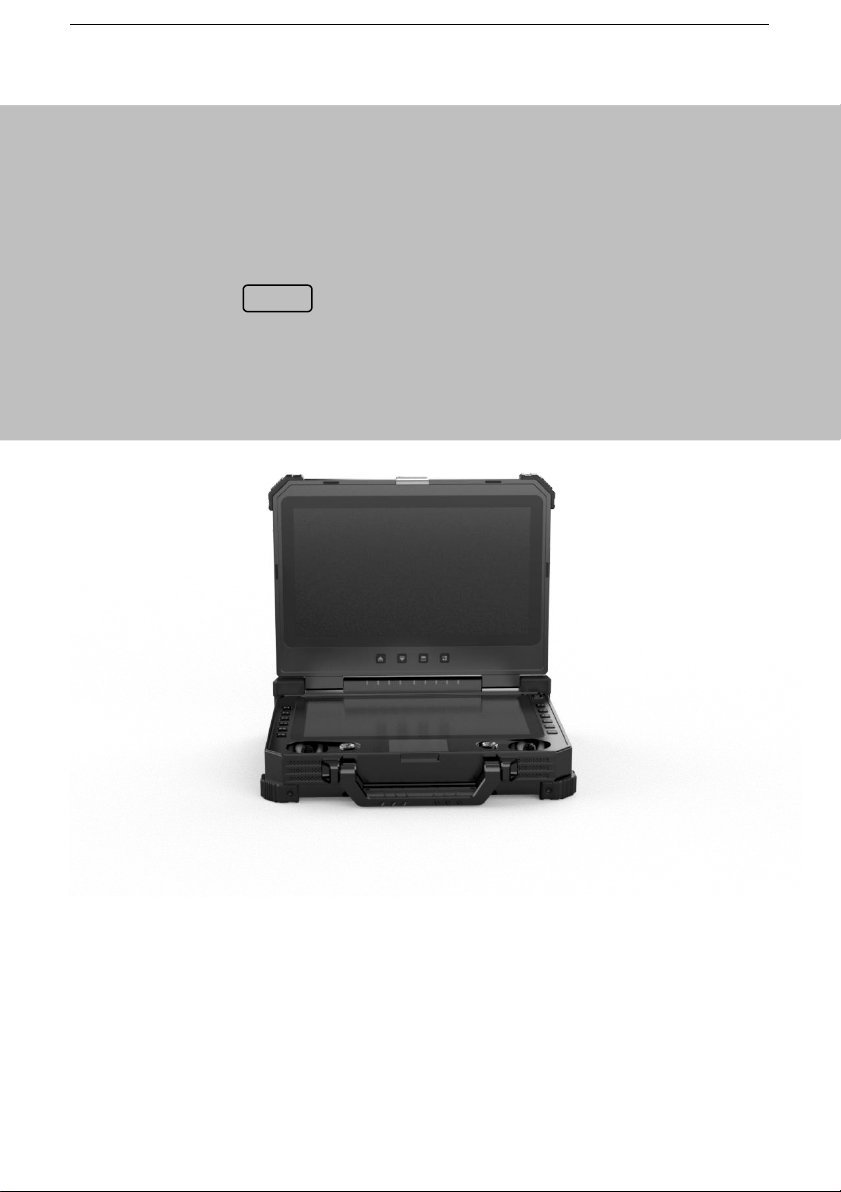
3. Product Introduction
T40 is all-in-one hand-held GCS that integrates remote control, data transmission
module, video transmission module and industrial computer. High integration,
dual screens display, dual SBUS output, easy operation. There are 20 physical
channels and 7 virtual channels to map to any channel of SBUS. Multiple
frequencies for choice, 800MHz, 1.4GHz and 2.4GHz. It can be used widely in
commercial unmanned applications for remote control and data transmission.
4. Item List
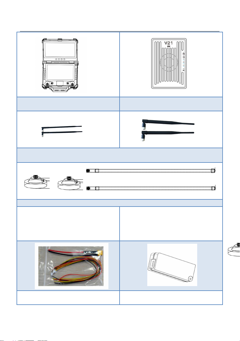
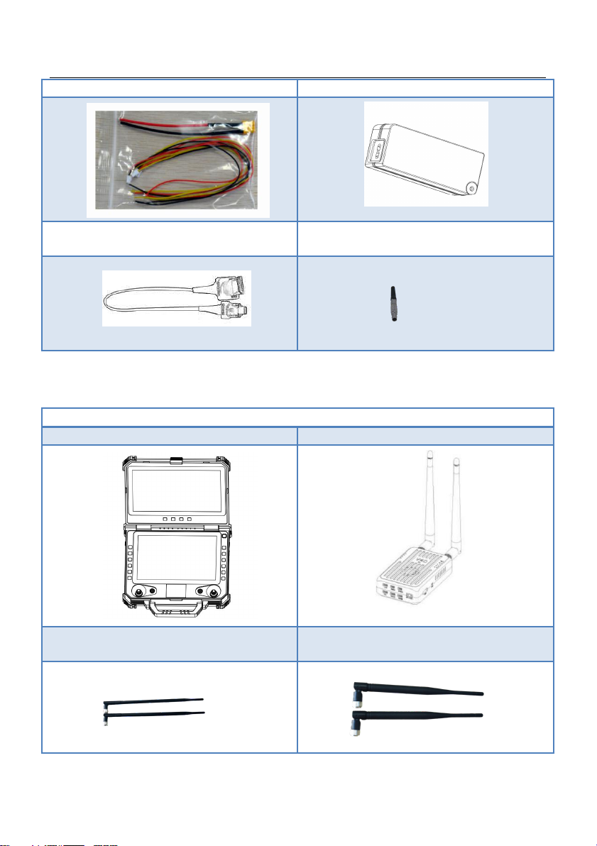
4.1 V21 Version
Main module
T40 Remote Control*1
V21 Receiver*1
www.chinowing.com
7
TNC ZYJB antenna*2
(For T40 remote control)
SMA ZYJB antenna*2
(For V21 receiver)
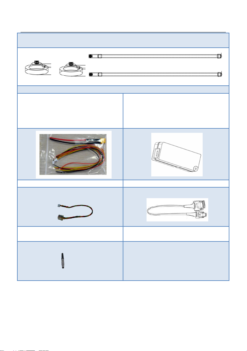
Fibre-glass epoxy antenna
(TNC sucker*2, TNC fibre glass epoxy antenna*2)
Accessories
Cables
(XT40 power cable*1;
SBUS signal wire GH 3pin*2;
TTL signal wire GH 4pin*1;
Aviation plug 6pin*1)
Charger*1
(DC16.8V, charging for RC)
LAN-to-4Pin wire*1
(used for module parameters setting)
www.chinowing.com
8
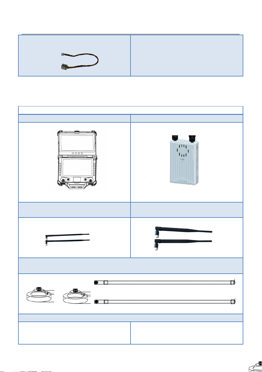
4.2 V30 Version
Main module
T40 Remote Control*1
V30 Receiver
TNC ZYJB antenna*2
(For T40 remote control)
SMA ZYJB antenna*2
(For V30 receiver)
Fibre-glass epoxy antenna
(TNC sucker*2, TNC fibre glass epoxy antenna*2)
Accessories
Cables
(XT40 power cable*1;
SBUS signal wire GH 3pin*2;
Charger*1
(DC16.8V 6V, charging for RC)
www.chinowing.com
9
TTL signal wire GH 4pin*1)
HDMI wire
(HDMI A to micro)
Aviation Plug 6pin
4.3 V40 Version
Main module
T40 Remote Control*1
V40 Receiver
TNC ZYJB antenna*2
(For T40 remote control)
SMA ZYJB antenna*2
(For V40 receiver)
www.chinowing.com
10
Fibre-glass epoxy antenna
(TNC sucker*2, TNC fibre glass epoxy antenna*2)
Accessories
Cables
(XT40 power cable*1;
SBUS signal wire GH 3pin*2;
TTL signal wire GH 3pin*1;
GH 4pin*5)
Charger*1
(DC16.8v 6A, charging for RC)
LAN-to-4Pin wire*1
HDMI-to-HDMI micro*1
Aviation plug 6pin

www.chinowing.com
11
5. Product Instruction
5.1 T40 GCS
1.T40 副屏 2. 输出 SBUS 和 rs232 信号 3.网口
1. GCS main screen: the computer main interface display
2. GCS secondary screen: used for split screen and external input display
3. Power supply button and indicator: used for power-on and power-off the GCS
4. Upper screen brightness +: used to adjust the brightness and Menu up
5. Upper screen brightness -: used to adjust the brightness and Menu down
6. External HDMI Switch: for external HDMI and computer split screen switching
7. Menu key of upper screen function: used to enter menu settings of the upper screen
8. Touch panel: Used to control the mouse cursor
9. Main joysticks: corresponding to T1, T2, T3, T4 channels
10. Secondary joysticks: corresponding to T5, T6, T7, T8 channels
www.chinowing.com
12
11. Buttons channel: corresponding to F1-F12, 12 buttons
12. Power indicators: 1 indicator stands for 25% battery capacity
13. Wireless link indicators: indicating signal strength; in the flow light state when no
connection
14. Transparent transmission data indicators: Tx light ON when there is data transmitting;
Rx light ON when there is data receiving.
15. Battery charging port: DC16.8V 6A input
16. Power supply output interface: DC12V 3A output
17. 6 Pin Aviation Plug: corresponding to RS232 Level, COM4, 2 channels of SBUS
18. 4 Pin Aviation Plug: corresponding to LAN port of the computer
19. SIM card slot: for installing SIM card
20. 3*RS232 serial port: corresponding to COM1, COM2, COM3.
21. External SBUS input: corresponding to SBUS2 signal output
22. Audio interface and LAN port: for audio output and Ethernet connection
23. USB, VGA, HDMI interfaces: used for SUB communication and video output
24. Antenna interface: corresponding to slave antenna
25. Antenna interface: corresponding to main antenna
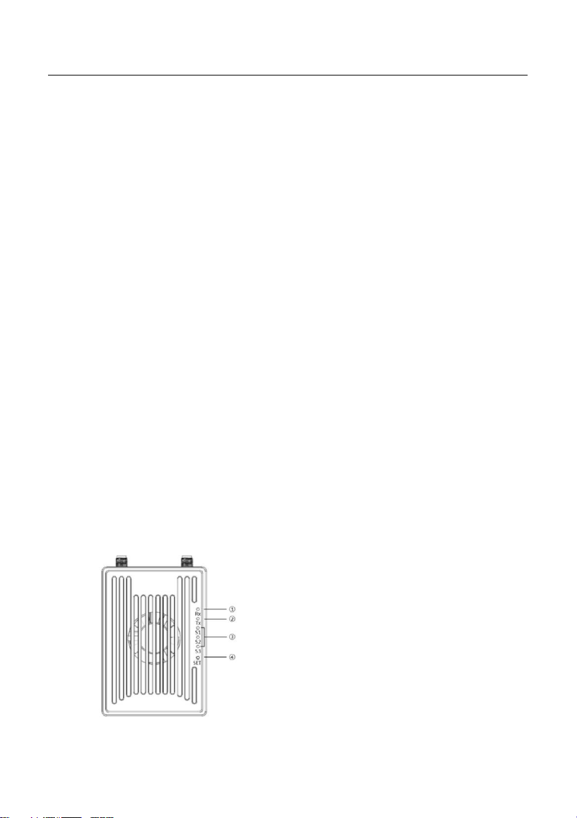
5.2 V21 Receiver
5.2.1 V21 Receiver Indicator&Port Instruction
Front view
① Data receiving indicator: light will flicker in the condition of data receiving.
www.chinowing.com
13
② Date transmitting indicator: light will flicker in the condition of data
transmitting.
③ Signal strength indicator: S3 ON, signal is weak; S3 and S2 ON, signal is
moderate; S3, S2 and S1 ON, signal is strong.
④SET button: used for firmware upgrading, serial port baud rate setting, Failsafe
protection setting
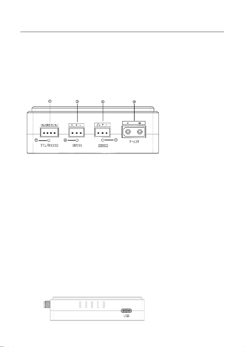
Side View
①TTL port: full duplex serial port
②S-BUS1port: SBUS input(ground unit);SBUS output(airborne unit)
③S-BUS2 port: SBUS input(ground unit);SBUS output(airborne unit)
④Power supply port: 7.4-12V
⑤TTL signal indicator: light will flicker when there is data input
⑥SBUS1 indicator:
Ground unit: SBUS1 indicator will flicker when there is data input of SBUS1.
Airborne unit: SBUS1 indicator will flicker when there is data output of
SBUS1.
⑦SBUS2 indicator:
Ground unit: SBUS2 indicator will flicker when there is data input of SBUS2.
Airborne unit: SBUS2 indicator will flicker when there is data output of
SBUS2.

www.chinowing.com
14
LAN port: for video input or output
USB port: debugging interface, for video output
By default, the S-BUS1 and S-BUS2 interfaces output the CH1 to CH16 of the remote
control to 1-16 channels.
5.2.2 V21 Receiver Installation and Connection
1. Connecting antennas to SMA port of Rx.
2. Fix the receiver to the appropriate position of the aircraft by using double-
sided tape.
3. As shown in the above photo, connecting TTL port and S-Bus port of the V21
receiver to your device by lead wire of servo.
TTL port
SBUS port
RX
TX
S
S
Receiver GND
GND Flight control
Receiver +
+ Flight control
TX
RX (or other device)
-
- (or other device)
www.chinowing.com
15
4. With 7.4-12v DC power supply, S1-S3 indicators ON, it indicates the successful
connection between transmitter and remote control
5. Video interface is LAN port, LED light of LAN port will flash after the
successful connection.
6. If you are using a dual S-BUS receiver. Both S-BUS1 and S-BUS2 can output the
CH1 to CH16 of the remote control. The output of S-bus1 and S-bus 2 can be
mapped separately. Pls refer to the output mapping description.
The receiver power is 1W by default, please keep the receiver antenna away from other
electronic devices (GPS, compass, etc.) to avoid interference with it and affect the flight.
Make sure to install the antennas before power-on, otherwise it may burn out the radio module.
When using, the antenna, try to make the antenna downward and no obstacle blocking, to
avoid the communication distance is shortened due to blocking, or even unable to
communicate.
Be sure to use the specified type of antenna and install it correctly. It is forbidden to use
other types of antennas.
5.3 V30 Receiver
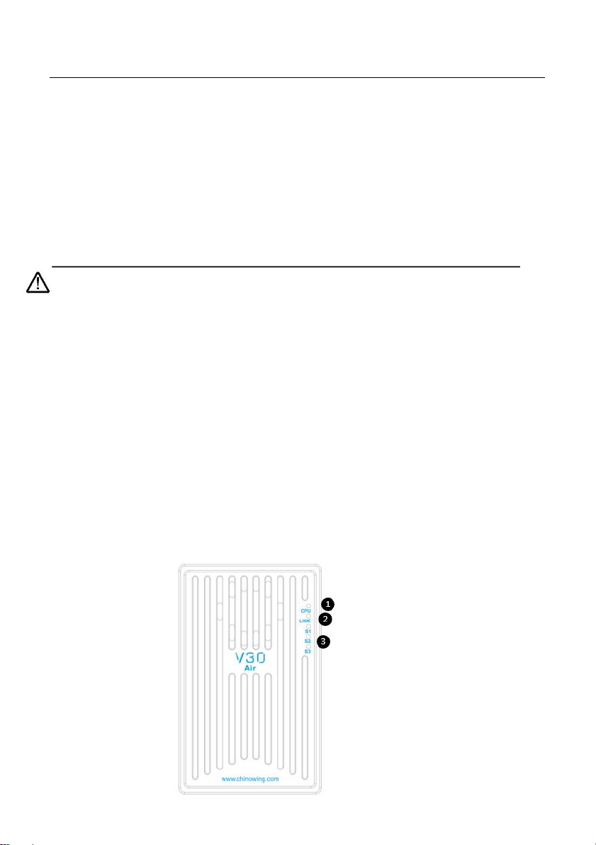
5.3.1 V30 Receiver Indicator&Port Instruction
Front view
www.chinowing.com
16
①Video link CPU indicator: light will be continuously ON in normal working
condition.
②Data link indicator: indicator will be continuously ON when the connection of
TX and RX is successfully established.
③Signal strength indicator: S3 ON, signal is weak; S3 and S2 ON, signal is
moderate; S3, S2 and S1 ON, signal is strongest.
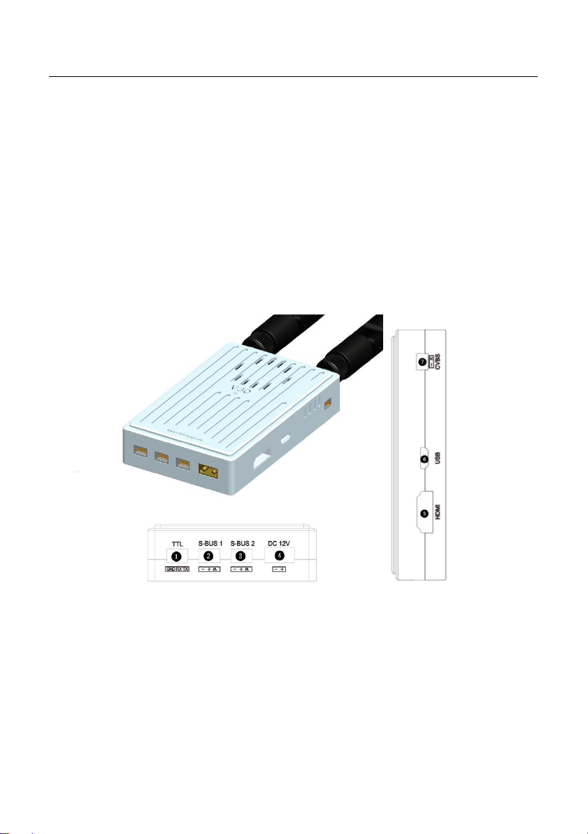
Side View
①Data transmission port: TTL level, in transparent transmission with the COM6
in the computer
②SBUS 1 port: used for connecting flight controller or payload
③SBUS 2 port: used for connecting flight controller or payload
④Power supply port: 7.4-12V
⑤HDMI video input interface: connecting camera

www.chinowing.com
17
⑥USB port: used for firmware upgrading and parameters setting
⑦CVBS video input interface: used for analog video input.
By default, the S-BUS1 and S-BUS2 interfaces output the CH1 to CH16 of the remote
control to 1-16 channels.
5.3.2 V30 Receiver Installation and Connection
1. Connecting antennas to SMA port of Rx.
2. Fix the receiver to the appropriate position of the aircraft by using double-
sided tape.
3. As shown in the above photo, connecting COM port and S-Bus port of the V30
receiver to your device by lead wire of servo.
TTL port
SBUS port
RX
TX
S
S
Receiver GND
GND Flight control
Receiver +
+ Flight control
TX
RX (or other device)
-
- (or other device)

www.chinowing.com
18
4. Connect the camera to V30 HDMI interface, CPU indicator will be continuously
ON with successful video input.
5. Power on by 7.4-12V DC power supply, LINK indicator will be continuously
ON. It means the successful connection between Receiver and Remote Control.
6. If you are using Receiver with dual SBUS output. SBUS1 and SBUS2 will output
control signal of (CH1-CH16) channels from Remote Control. And SBUS1 and
SBUS2 can be mapped separately.
By default, the S-BUS1 and S-BUS2 interfaces output the CH1 to CH16 of the remote
control to 1-16 channels.
5.4 V40 Receiver
5.4.1 V40 Receiver Indicator&Port Instruction

www.chinowing.com
19
① SBUS status indicator
Indicating data status of SBUS1 and SBUS2
② COM serial port module indicator
Serial port module self-check indicator
③ HDMI signal indicator
HDMI signal input status indicator
④ Work self checking status indicator
Self-checking indicator is always on, which means normal operation, OFF
means start-up or failure
⑤ SET button
For out-of-control protection Settings
⑥ POWER indicator
⑦ Data link establishing indicator
Indicator to indicate the data link connection status between the airborne
unit and the ground unit
⑧ Signal strength indicator
Indicator S1, S2, S3 are used for indicating signal strength
⑨ HDMI interface
HDMI video input
⑩ CVBS video input interface
CVBS video input
⑪ LAN port
Used for transmit the video or read the V40 parameters
⑫ SBUS1 interface
For Sbus1 signal output
⑬ SBUS2 interface
For Sbus2 signal output
⑭ TTL port: Full-duplex serial port

www.chinowing.com
20
⑮ RS232 port: Full-duplex serial port
⑯ RS485 port: Half-duplex serial port
⑰ Power supply interface: support 7.4v-24V input
5.4.2 V40 Receiver Installation and Connection
After the connection is completed, please refer to the following steps to check the
connection status. (This step may vary depending on the ground connection or
flight control)
1. TTL port and SBUS port connection sequence
TTL port
SBUS port
5V
5V
RX
TX
S
S
Air GND
GND Flight control
Air +
+ Flight control
TX
RX (or other device)
-
- (or other device)
2. RS232 port and RS485 port connection sequence
RS232 port
RS485 port
5V
5V
5V
5V
GND
GND
GND
GND
Air TX
RX Flight control
Air A
A Flight control
RX
TX (or other device)
B
B (or other device)
3. With a stable 7.4-24V DC power supply, POWER indicator ON, indicates that
the transmitter is normally powered on; when the LINK indicator is always on, it
means the successful connection.
4. When the COM indicator is on, it means that the serial module starts normally,
and when the WORK indicator is on, it means that the self-test of the airborne
Table of contents


