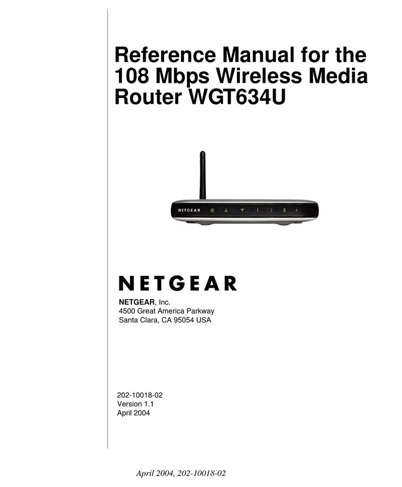
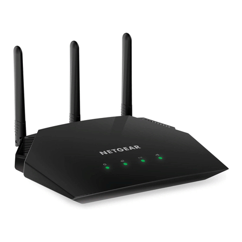
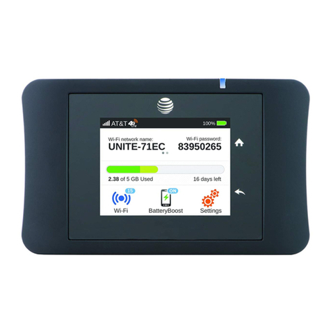
MeshNetworks MEA EWR6300 User manual

Enhanced Wireless
Router
User’s Guide
Version 3.0
Copyright 2003-2004, MeshNetworks, Inc. All Rights Reserved


MEA EWR User’s Guide
Foreword
This document describes in detail the confidential and proprietary technology of MeshNetworks’
MEA™ Architecture. MeshNetworks’ products and technology are protected by US and
international patent and patent pending technology. This document represents the current MEA
design; the contents are subject to change at any time at the discretion of MeshNetworks, Inc.
MEA, MeshTray, and MeshNetworks’ logo are trademarks or registered trademarks of
MeshNetworks, Inc. All other product names and services identified throughout this publication
are trademarks or registered trademarks of their respective companies. No such uses or the
use of any trade name is intended to convey endorsement or other affiliation with this
publication.
Copyright © 2003-2004 MeshNetworks, Inc. All Rights Reserved
i


MEA EWR User’s Guide
Table of Contents
1ENHANCED WIRELESS ROUTER.......................................................................................1
1.1 Introduction.................................................................................................................1
1.2 What’s in the Box .......................................................................................................1
2INSTALLATION REQUIREMENTS.......................................................................................1
2.1 Enhanced Wireless Router (EWR)............................................................................2
2.1.1 Equipment .........................................................................................................2
2.1.2 Record MAC Address of the EWR6300 ............................................................3
2.1.3 EWR6300 Assembly..........................................................................................4
2.1.4 Deployment .......................................................................................................4
2.1.5 Deployment Tips................................................................................................5
2.1.6 Initial Configuration............................................................................................5
2.1.7 Testing...............................................................................................................5
3INSTALLING THE MEA ENHANCED WIRELESS ROUTER...............................................7
3.1 Device Administration: Configuring the EWR Devices...........................................7
3.1.1 Accessing the MEA Device Administration Web Pages....................................7
3.1.2 Configuring the Device....................................................................................11
3.1.2.1 Device Addressing.......................................................................................12
3.1.2.2 Network DHCP Scheme..............................................................................12
3.1.2.3 Statically Provisioned Scheme....................................................................13
3.1.2.4 User Supplied Scheme................................................................................13
3.1.2.5 Setting the User Supplied IP Address.........................................................14
3.1.3 Resetting the EWR..........................................................................................16
3.1.4 Restoring Factory Settings – User Supplied Mode Limitations .......................18
3.1.4.1 EWR Reset-to-Default Recovery In User-Supplied Mode...........................18
3.1.4.2 Reset the Device Addressing Mode Using DeviceManager........................18
3.1.4.3 Reset the Device Addressing Mode via the Configuration Web Page.........18
iii

MeshNetworks
3.1.4.4 Reset the User-Supplied Parameters via the Configuration Web Page......18
3.1.5 Restoring Factory Defaults – Normal Operations............................................19
3.1.6 Changing the Web Password..........................................................................21
3.1.7 Upgrading the Device Firmware......................................................................23
3.2 External Device Provisioning..................................................................................25
3.2.1 Connecting to the Ethernet Port......................................................................26
3.3 Infrastructure Requirements...................................................................................26
3.4 EWR6300 Mounting Bracket....................................................................................27
3.4.1 EWR MAC Addresses.....................................................................................29
4LICENSE AND WARRANTY INFORMATION ....................................................................30
4.1 Important Information..............................................................................................30
5FCC REGULATORY INFORMATION.................................................................................32
5.1 FCC Information .......................................................................................................32
5.2 FCC RF Radiation Exposure Statement .................................................................32
6SAFETY INFORMATION FOR THE MEA PRODUCTS .....................................................33
7SAFETY CERTIFICATION..................................................................................................33
7.1 CE Mark Certification...............................................................................................33
iv

MEA EWR User’s Guide
List of Figures
Figure 2-1. EWR6300 Identification Label ............................................................................3
Figure 2-2. EWR6300 External Connection Points..............................................................4
Figure 2-3 Typical EWR Depoyment....................................................................................5
Figure 3-1. Enter Network Password Initial Web Page Authentication Dialog .................8
Figure 3-2. MEA Device Administration Redirecting Web Page.........................................9
Figure 3-3. MEA Device Administration Home Page (Super User Login)........................10
Figure 3-4. EWR Device Administration Configuration Page (Super User Login)..........11
Figure 3-5. Configuration Change Verification..................................................................14
Figure 3-6. System Update Save Completed Web Page ...................................................15
Figure 3-7. Device Reset Prompt Web Page ......................................................................16
Figure 3-8. Device Reset in Progress Web Page...............................................................17
Figure 3-9. Restore Factory Settings Web Page................................................................19
Figure 3-10. Confirm Changes Window for Restore Factory Settings .........................20
Figure 3-11. Factory Settings Restored Web Page..........................................................20
Figure 3-12. Enter New Password Web Page..................................................................21
Figure 3-13. Confirm Changes Window for Enter New Password .................................22
Figure 3-14. Password Changed Confirmation Web Page..............................................22
Figure 3-15. Update Device Firmware Web Page.............................................................23
Figure 3-16. Confirm Upload Window for Firmware Update..........................................24
Figure 3-17. Firmware Upload Progress Web Page.........................................................24
Figure 3-18. External Device Provisioning Table.............................................................25
Figure 3-19. EWR6300 Mounting Bracket.........................................................................27
Figure 3-20. C-Clamp Bracket Assembly..........................................................................28
Figure 3-21. EWR Pivot and Angle Locking Bolts ...........................................................29
v


MEA EWR User’s Guide
1 Enhanced Wireless Router
1.1 Introduction
Thank you for purchasing the MEA Enhanced Wireless Router (EWR). MEA is a wireless
communication system capable of supporting high data rate mobile communication at variable
rates of vehicular speeds.
The Enhanced Wireless Router (EWR™) is designed to be deployed outdoors for wireless
coverage in large geographic areas to wireless network access to one or more IP devices via its
built-in RJ45 Ethernet port. The EWR efficiently combines the functionality of a Meshnetworks
Wireless Router and client modem in to a single cost-effective wireless network component.
This makes it easy for any Ethernet ready device to access a Mesh Enabled Architecture
(MEA™) mobile broadband network. IP-enabled computers, video cameras, sensors, signs,
signals, etc. can all be Mesh-Enabled to send and receive data at burst rates of up to 6 Mbps.
All standard Wireless Router functionality including Multi-Hopping™, near line of sight
communications and geo-location services are fully supported.
The MEA Enhanced Wireless Router is configured for the connection of multiple IP addressable
devices using standard Ethernet connectivity. This allows devices that cannot accept the
PCMCIA based WMC3600 product to function transparently on a MEA network without drivers.
This document provides detailed installation and configuration instructions for installing the MEA
EWR.
1.2 What’s in the Box
Each MEA EWR is a full-featured wireless networking device. The following is a list of the items
provided with each EWR:
• MEA Enhanced Wireless Router
• High Gain Antenna
• Power Cord
2 Installation Requirements
NOTE: All Intelligent Access Points (IAPs) on the MEA network require a software upgrade to
support EWR Devices.
The EWR will require the following in a typical installation:
• Power Cord
• 110/220 volts AC Power along with appropriate power connection cable
• A Hub or Switch (Use of a X-Over cable is not recommended at this time)
• Antenna and RF cabling appropriate for use in the 2.4 GHz band
1

MeshNetworks
2.1 Enhanced Wireless Router (EWR)
The MEA Enhanced Wireless Router 6300 (EWR6300) is an infrastructure device positioned in
a fixed location, such as on a pole, wall, or rooftop. The EWR6300 requires professional
installation to ensure the installation is performed in accordance with FCC licensing regulations.
The EWR6300 provides range extension, a means to route around obstructions, a fixed location
reference for use in Geo-Location, and the capability of enabling IP devices.
The EWR6300 comes with a mounting bracket that can be attached to a pole with a diameter of
1-3.5 inches. For a MEA deployment, a power source for each EWR must be provided.
2.1.1 Equipment
The following list defines the standard MEA hardware components needed to set up a EWR:
• EWR Box with N-type Antenna Connector
• 120V A/C Power Cable with a NEMA 5-15 plug
• Antenna with N-type Male Antenna Connector
• Mounting Bracket
The Network Operator must supply the following:
• Mounting Location
• Power Source (120V A/C or 5 V D/C depending on EWR configuration)
• Hand tools for bracket installation (7/16” wrench (2), Phillips screwdriver)
Optional Equipment:
• DC powered EWR (EWR6300-DC-IN)
• Power cord to connect to a photoelectric cell
Optional FCC Approved Antennas:
Manufacturer Part Number Gain Usage
Maxrad MFB24008 8 dBi Infrastructure
Maxrad MFB24004 4 dBi Infrastructure
Hyperlink HG2409U 8 dBi Infrastructure
2

MEA EWR User’s Guide
2.1.2 Record MAC Address of the EWR6300
The transceiver Media Access Control (MAC) address is recorded on the label located on the
antenna end of the EWR6300 and the Ethernet MAC address is recorded on the label located
on the antenna end of the EWR6300 as show in Figure 2-1.
Record the MAC Address and ETH MAC Address in the tables in Section 3.4.1, because it will
be required later to configure and test the device.
ETH MAC
Address
MAC
Address
Figure 2-1. EWR6300 Identification Label
3

MeshNetworks
2.1.3 EWR6300 Assembly
Figure 2-2 shows the external connection points on a EWR6300 box.
Figure 2-2. EWR6300 External Connection Points
e:
nclosed bracket. Refer to the EWR6300
A
ntenna Connecto
r
Power Out (3-pin)
(
o
p
tional
)
Power In (4-pin)
Test Port
(Not Shown) RJ45 (Data) Port
Assemble the EWR using the following procedur
1. If desired, mount the EWR box using the e
Mounting Bracket section.
2. N-type Connector on the top of the box, and rotate to close.
3.
4. address has been recorded in Section
Insert the Antenna into the
Insert the Power Plug into the 4-pin Connector.
Verify the MAC address and Ethernet (ETH)
3.4.1. Both addresses will be required to configure and test the device.
5.
2.1.4
unted on a pole by using the bracket provided.
minimum of 30 inches
from the body
provided with antenna installation and transmitter
Typically, enh k to extend the range,
e device.
ny
The Test Port is unused during deployment.
Deployment
The EWR6300 can be mo
NOTE: When deploying the EWR6300, the antenna should be a
from any nearby metal poles to avoid distortion of the RF pattern.
The antenna must have a separation distance of at least 2 meters
of all persons and must not be co-located or operating in conjunction with any
other antenna or transmitter.
Users and installers must be
operating conditions to satisfy RF exposure compliance.
anced wireless routers are distributed within a networ
guarantee coverage, and mesh enable an Ethernet Internet Protocol (IP) device. A rule of
thumb is to deploy 2-3 hop networks to optimize range, latency, and throughput.
The EWR6300 installation location must provide applicable AC or DC power for th
It is the responsibility of the Network Operator to ensure that the installation complies with a
local building codes and permits.
4

MEA EWR User’s Guide
Figure 2-3 Typical EWR Depoyment
2.1.5 Deployment Tips
multipath:
rference from nearby transmitters
nnection to other
• nna supplied is designed to be mounted vertically
he devices are designed to be vertically mounted with the antenna port at the top or the
2.1.6 Initial Configuration
Location is the same as the setup for the IAP as described in
2.1.7 Testing
of the EWR6300 using the following procedure:
1. Apply power to the EWR6300.
dress and ETH address that was recorded in Section
Locate the antenna to minimize
• Minimize inte
• Maximize chance of a direct line of sight co
devices
The ante
T
bottom. The antenna is specified around deployment heights of 3-30 meters. Remotely locating
the antenna will degrade the performance through cable loss, though this may be mitigated by
better antenna positioning.
The configuration process for Geo-
the mea Setup and Deployment User’s Guide for Infrastructure Mode User’s Guide.
Verify the operation
2. Obtain the transceiver MAC ad
3.4.1. The address will be in the form of 00-05-12-0A-xx-yy.
3. he MAC address.
o test
communications with the device.
From the MeshManager user interface, display devices using t
4. Select the appropriate EWR in the device tree, right click and select ping t
5

MeshNetworks
nse to the ping command verifiesA respo that the transceiver is communicating.
NOTE: If you are running an EWR as a standalone device, the configuration web page can be
reached by connecting a PC to the wired interface.
6

MEA EWR User’s Guide
3 Installing the MEA Enhanced Wireless Router
3.1 Device Administration: Configuring the EWR Devices
The EWR provides network access to one or more IP devices connected to the Ethernet port of
the EWR. In order for the EWR to provide service to the IP devices, some configuration must
be set up prior to connecting the IP devices.
The EWR serves as a default gateway for the attached IP devices. Because some devices
expect the default gateway to reside on the local subnet, the address that the EWR uses for
gateway service (on the wired interface) must be configurable. Some consideration should be
used in selecting a gateway address for the EWR.
The local default gateway address is used only on the wired interface, and is only visible to the
attached IP devices. It is not advertised to the wireless network, and the network cannot
access the EWR using this gateway address. The EWR has another IP address for the
wireless interface that can be used to access the EWR from the network. Because is gateway
address is limited to the local wired interface, the same address could be used for the gateway
service in several EWR devices. The local gateway should be a part of the overall subnet
chosen for your MEA network.
When selecting IP addresses for the EWR, care must be taken to ensure that the selected IP
addresses do not conflict with any other devices on the mea network.
3.1.1 Accessing the MEA Device Administration Web Pages
To modify the IP configuration for the EWR using the web interface, you must know the IP
address assigned to the wireless interface of the EWR. The IP address can be determined
from MeshManager, or from the DHCP server (once the device is configured for DHCP). The
default IP address for the EWR wireless interface is derived from the transceiver MAC address
(10.xx.yy.1, where the MAC address is 00:05:12:0A:XX:YY), similar to the default IP addresses
described in Section 3.2.
Once the IP address is known, you can access the web page of the device. Point your web
browser to the IP address of the EWR. In the examples following, the EWR address is
172.16.1.53, and the web page would be found at http://172.16.1.53/.
7

MeshNetworks
Once the web browser is directed to the web page of the EWR, you will be prompted for a
username and password. A dialog box similar to the following should show up if you are using
Internet Explorer:
Figure 3-1. Enter Network Password Initial Web Page Authentication Dialog
The username is admin, and the default (initial) password is admin.
The password for the admin account should be changed during installation.
The device has two accounts for the web pages - an administrative account (username:admin,
default password:admin), and an access account (username: monitor, default password:
monitor). The administrative account must be used for provisioning the device, and the access
account may be used for monitoring the status of the device.
The installation procedure described here requires administrator access. Alternatively, all of the
parameters that are provisioned via the web page may be provisioned via MeshManager
instead.
The administrator has the ability to change the password for the access account.
NOTE: If you are running an EWR as a standalone device, the configuration web page can be
reached by connecting a PC to the wired interface.
8

MEA EWR User’s Guide
After the login authentication has been completed, the web browser will display a redirecting
page, and your browser will automatically transition to the home web page for MEA Device
Administration.
Figure 3-2. MEA Device Administration Redirecting Web Page
9

MeshNetworks
Figure 3-3. MEA Device Administration Home Page (Super User Login)
The MEA Device Administration home page provides you with some basic information about
the device, including the IP addresses assigned to the device, the MAC addresses of the
device, the firmware revision number, and the reported link quality for the link to the IAP. In
addition, links are provided to web pages for device configuration, password management,
firmware upgrades, device reset, and restoring the factory default configuration.
10

MEA EWR User’s Guide
3.1.2 Configuring the Device
Once you have accessed the MEA Device Administration home page, click on the
Configuration tab to display the IP address configuration.
Figure 3-4. EWR Device Administration Configuration Page (Super User Login)
The EWR Device Administration (Super User Login) page will allow you to change the
configuration of the EWR. The fields displayed on this page are described below.
Field Name Field Description Field Default Value
System Name This is the name of the device as shown by
MeshManager
11

MeshNetworks
Field Name Field Description Field Default Value
MeshManager
RDATE Server IP
Address The IP address of the RDATE server. This is
usually the MiSC when operating in
infrastructure mode. The RDATE server
provides the current date to the EWR. The
EWR can operate without an RDATE server.
172.31.0.20
Wired Interface
Address The EWR will tell the attached Ethernet devices
to use this address for the default gateway, and
the EWR will use the address when accessing
the local Ethernet segment.
MAC-derived
Wired Interface
Subnet Mask This is the subnet mask for the local Ethernet
segment. 255.255.0.0
DHCP Lease Time This is the duration (in seconds) of the DHCP
leases that the EWR offers to the attached
Ethernet devices.
300
Device Priority The Device Priority provisioning area allows the
operator to set the priority assigned to wireless
messages transmitted by this device.
Geo Reference The Geo Reference area allows the operator to
provision the exact location of the EWR so that
it can serve as a geographical reference for the
mea network. Enter the Latitude and Longitude
in degrees and the Altitude in feet.
The External Device Provisioning frame of this web page is described in Section 3.2.
A similar screen will be displayed for the access account (the web page will indicate Normal
User Login). Normal users can change only those settings for which they have system
privileges.
3.1.2.1 Device Addressing
With mea Release 3.0, the concept of modes has been replaced by a Unified Modes of
operation addressing scheme. The concept of unified modes of operation centers on the current
state of network communication: Associated State and Unassociated State. There are three
addressing schemes which allow the IT manager increased flexibility in deployment.
3.1.2.2 Network DHCP Scheme
Operation under the Network DHCP scheme is similar to that of Release 2 in Infrastructure
Mode. The primary difference is that loss of infrastructure does not force loss of connectivity.
Network DCHP requires that the EWR device be configured to request an address from a
DHCP server and the inclusion of a DHCP server in the core network configuration to answer
these requests. With Network DHCP selected, the EWR will send DHCP requests for its own
address to the core network once it becomes associated and establishes communications with
the infrastructure.
12
Table of contents
