METHVEN AURAJET User manual

www.methven.com
Technical Specifications:
Operating Pressure:
Min: 100kPa/1bar
Max: 500kPa/5bar*
Optimum: 150kPa/1.5bar - 500kPa/5bar
Operating Temperature:
Hot: Max 70°C*
Cold: Min 5°C
Inlet Connections:
½" BSP
* Regional specific regulations apply.
Please refer to your warranty statement at
www.methven.com
AURAJET™ HANDSET
Installation Guide

Methven warrants this product against manufacturing defects and that it is suitable for use
under the general operating conditions specified in this instruction sheet. However, regional
regulations apply and may affect your warranty. Please refer to www.methven.com or call
customer service for full details.
New Zealand
0800 804 222
Australia
1300 638 483
UK
0800 195 1602
Never use abrasives or abrasive cleaning agents to clean this product. Clean regularly with
contamination free warm soapy water and a damp soft cloth.
A filter washer should be installed in the hose cone on the water outlet and it should be
cleaned periodically.
If shower performance is compromised by the build-up of lime-scale, soak in limescale
remover for up to 10 minutes. Do not use products containing chlorine bleach or
hydrochloric acid as these can damage the shower. Always rinse the shower thoroughly after
cleaning to remove cleaning products that can damage the shower.
Never insert objects into the spray slot or attempt to remove limescale with sharp objects or
abrasives.
•
•
•
•
IMPORTANT: Please read all of the instructions before installation.
General:
Methven recommends this product is installed by a licensed plumber in compliance with all
relevant regional regulations.
After installation all connections must be checked for leaks.
All outlets used primarily for personal hygiene shall deliver water at a safe temperature as per
regional regulations.
It is the responsibility of the installer to ensure a waterproof seal is achieved.
NOTE: Some showers may not provide an effective shower when used with gravity fed heated
water systems or where pressures are less than 150kPa/1.5bar at the outlet. Additionally showers
with flow rates of less than 9L/min may not allow the following to function correctly:
- some instantaneous water heaters
- some tempering valves
- some thermostatic mixing valves
Care and Cleaning:
•
439910 ISSUE B

Methven warrants this product against manufacturing defects and that it is suitable for use
under the general operating conditions specified in this instruction sheet. However, regional
regulations apply and may affect your warranty. Please refer to www.methven.com or call
customer service for full details.
New Zealand
0800 804 222
Australia
1300 638 483
UK
0800 195 1602
www.methven.com
Never use abrasives or abrasive cleaning agents to clean this product. Clean regularly with
contamination free warm soapy water and a damp soft cloth.
Periodically the filter washer should be removed from the end of the shower hose and cleaned.
Care and Cleaning:
439980 ISSUE B
Technical Specifications:
Inlet Connections:
All ½" BSP
* Regional specific regulations apply.
Please refer to your warranty statement at
www.methven.com
EDGE RAIL
Installation Guide
•
Step 1
Wall lining hole should be cut or finished as per
the dimension shown in the diagram on the right.
Cut offthe threaded nipple 13±2mm from the wall
lining and apply thread seal tape to ensure a
good seal.
•
Step 2
Screw the elbow onto the nipple ensuring
that the o-ring is sufficiently compressed to
create a watertight seal.
Ensure that the elbow is oriented vertically
with the outlet oriented downwards.
•
•
Elbow Installation (if supplied):
13±2mm
26mm max
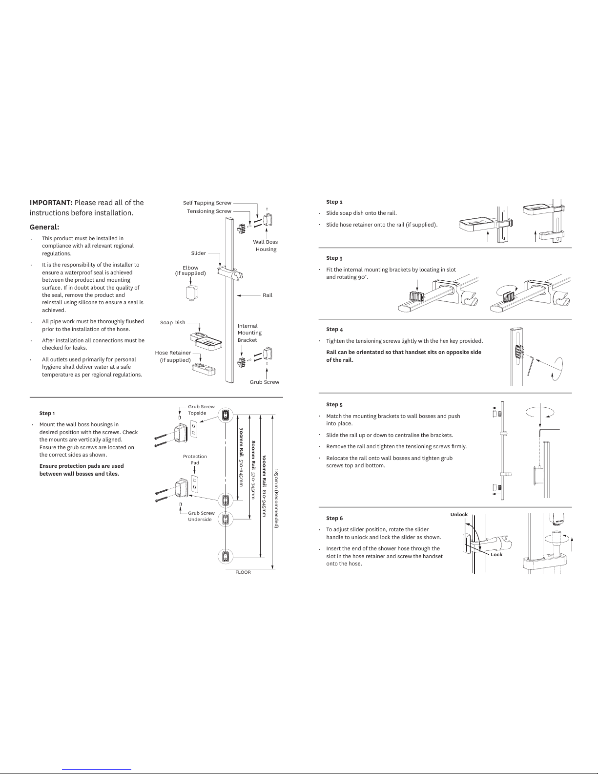
Step 2
Slide soap dish onto the rail.
Slide hose retainer onto the rail (if supplied).
Step 3
Fit the internal mounting brackets by locating in slot
and rotating 90°.
Step 4
Tighten the tensioning screws lightly with the hex key provided.
Rail can be orientated so that handset sits on opposite side
of the rail.
Step 5
Match the mounting brackets to wall bosses and push
into place.
Slide the rail up or down to centralise the brackets.
Remove the rail and tighten the tensioning screws firmly.
Relocate the rail onto wall bosses and tighten grub
screws top and bottom.
•
•
•
•
•
•
•
•
1850mm (Recommended)
1000mm Rail 810-945mm
700mm Rail 510-645mm
800mm Rail 570-745mm
Grub Screw
Underside
Grub Screw
Topside
Protection
Pad
FLOOR
Step 1
Mount the wall boss housings in
desired position with the screws. Check
the mounts are vertically aligned.
Ensure the grub screws are located on
the correct sides as shown.
Ensure protection pads are used
between wall bosses and tiles.
•
Tensioning Screw
Rail
Slider
Grub Screw
Internal
Mounting
Bracket
Elbow
(if supplied)
Soap Dish
Hose Retainer
(if supplied)
Self Tapping Screw
Wall Boss
Housing
Step 6
To adjust slider position, rotate the slider
handle to unlock and lock the slider as shown.
Insert the end of the shower hose through the
slot in the hose retainer and screw the handset
onto the hose.
•
•
Unlock
Lock
This product must be installed in
compliance with all relevant regional
regulations.
It is the responsibility of the installer to
ensure a waterproof seal is achieved
between the product and mounting
surface. If in doubt about the quality of
the seal, remove the product and
reinstall using silicone to ensure a seal is
achieved.
All pipe work must be thoroughly flushed
prior to the installation of the hose.
After installation all connections must be
checked for leaks.
All outlets used primarily for personal
hygiene shall deliver water at a safe
temperature as per regional regulations.
•
•
•
•
IMPORTANT: Please read all of the
instructions before installation.
General:
•
Please retain this document
for future reference.
This product should be fitted
in compliance with Water
Regulations, by a qualified
plumber.
Use only a clean damp cloth
to maintain the surface finish,
use of abrasive cleaning
materials will invalidate your
guarantee.
Website
www.methven.com
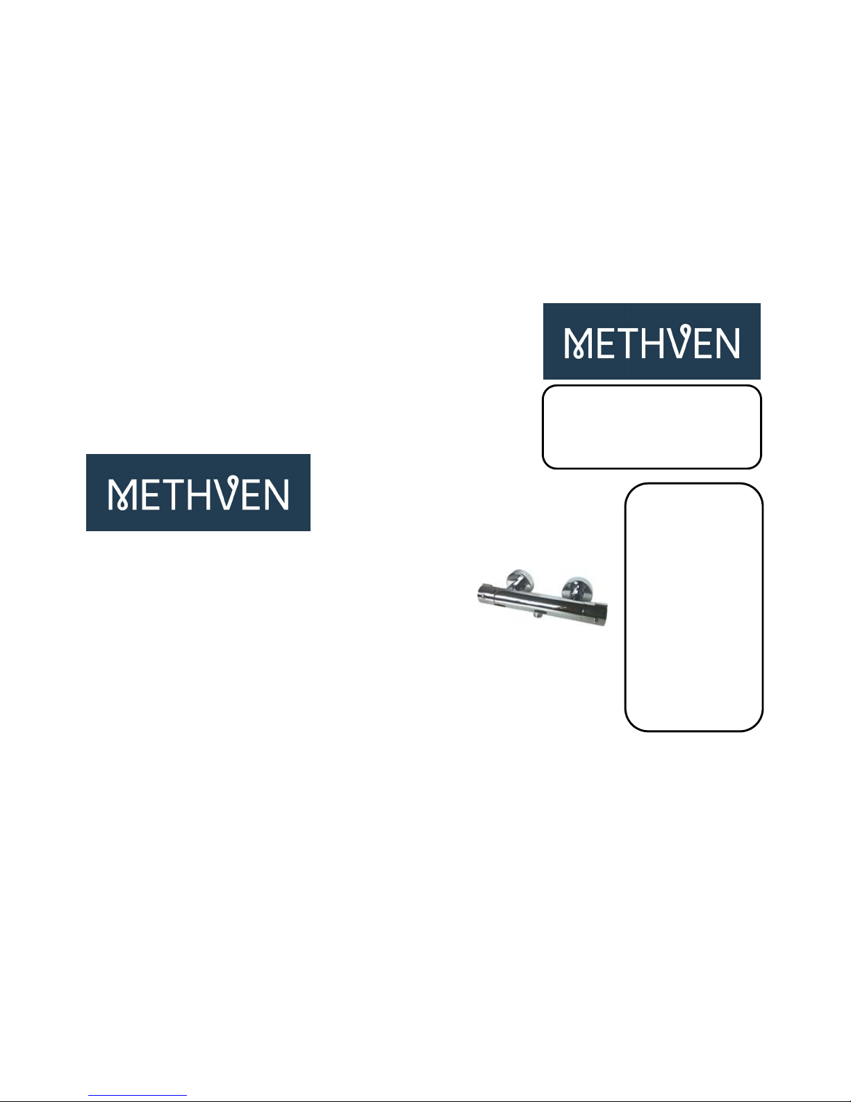
COOLTOUCHWITHEASYFIX
THERMOSTATICBARVALVE
InstallationandMaintenanceGuide
DTCINST274a‐25.09.14

Page 1 Page 6
OPERATING SPECIFICATION
Pressure
Minimum working pressure - 0.3 bar
Recommended working pressure 0.5 - 3 bar
Maximum working pressure - 5 bar
(Pressure above 5 bar must be reduced via a pressure reducer)
In order to assure maximum efficiency of the mixer, the operating pressures
should be balanced.
Water temperature
Inlet hot water supply
IMPORTANT
Maximum 85c
A minimum 10c difference between outlet
Recommended 65c
temperature and hot supply temperature
must be maintained at all times
Inlet cold water supply
10c - 25c
Guarantee
Your product comes with a 5 year guarantee, this includes 2 years parts and labour
followed by a further 3 years parts only, subject to the following:
Proof of purchase will be required.
The guarantee does not cover faults or damage caused by incorrect installation
and/or maintenance, ordinary wear and tear, water composition etc, including:
Supply pipes reversed
Incorrect pressure or temperature
Incorrect use
Foregin bodies and/or scale due to the water composition.
Incorrect cleaning
Cleaning should be carried out using a clean damp cloth, use of abrasive
agents or materials on the product, will invalidate your guarantee.
DTCINST274a‐25.09.14
Page 5 Page 2
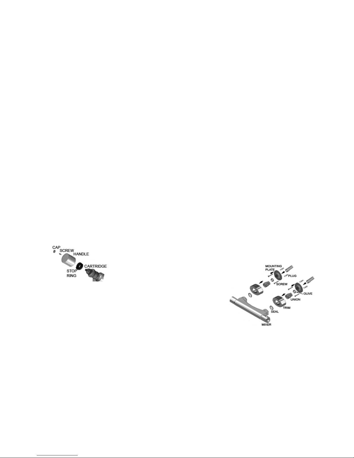
Maintenance Installation
To replace the thermostatic cartridge; (See diagram)
Turn off water supply
Remove the handle cap , followed by the screw
Inside the handle, remove the screw Prepare the supply pipes at 150mm centres, allowing approx 22mm of pipe to exposed
Pull handle from mixer from the finished wall.
Take note of the stop ring position for re-assembly after maintenance The pipework must be flushed prior to installation.
Remove the cartridge from the mixer body. After flushing the pipework, install the mixer as a standard exposed fitting, with the outlet
Clean or replace the cartridge as necessary, then replace, ensuring components are located facing downwards.
correctly to give correct maximum set temprature. The hot supply pipe must be connected to the hot inlet of the mixer, indicated by the red dot.
If re-calibration is required follow instruction in "operation and setting" Place the mounting plate over the pipe end and mark drill holes, ensuring no pipes or
Once water supply is turned on check for leaks. wires are affected.
Once holes are marked remove and drill holes, then fit wall plugs,
Next place the mounting plate over pipe end and locate over drill holes, secure using
screws provided.
Place olive over pipe end and then fit threaded union, tighten using a two spanners one
on the flats of the union the other on the flat of the mounting plate.
Tighten until fully secured, to create a compression fitting seal.
Once secured, screw the trim onto the threaded union and screw up to finished wall
(if required sealant can be used)
Place seals into mixer inlets and connect
mixer to union and secure using a spanner
(take care not to damage product finish)
Once all connections
have been made
turn on water supply to
check for leaks,
ensuring the valve is
in the OFF position
DTCINST274a‐25.09.14

Page 3 Page 4
OPERATION & SETTING Maintenance
To control the temperature of the shower, turn the left handle for more hot To replace the flow control valve:
or cold water, in the direction indicated by the marking. Turn off water supply
Remove handle by forcing off handle cap
To control the flow of water turn the handle to regulate the flow of water from the Inside the handle, remove the screw
shower in the direction shown on the mixer. Pull handle from valve.
Take note of stop ring positioning for re-fit
The product also has override buttons, the flow control allows for Pull off stop ring.
reduced flow, to activate full flow, press the button and continue Remove valve from mixer, using a spanner unscrew the nut
to turn the handle then unscrew the valve, taking care not to damage the pipe work
The temperature control allows for a temperature stop position Clean or replace valve as necessary.
this can be exceeded by pressing the button and continuing to Replace all components, turn on water supply and check for leaks.
turn the handle
If on installation the temperature is not to your requirement, this can be re-calibrated.
Turn temperature handle to fully hot.
Remove the handle cap , followed by the screw
Pull handle from valve.
Turn the spindle on the thermostat until the desired temperature is reached.
(Always maintain the 10c difference between supply and mixed)
Once the temperature is reached, replace the handle so that the stop is in the maximum
position, replace screw and handle cap.
Re-calibration should only be carried out when absolutely necessary
DTCINST274a‐25.09.14
Table of contents


