METRObility Optical Systems R711-11 Operation manual

Installation & User Guide
Models: R711-11 / R712-11
10 BASE
M
A
I
N
P
R
I
S
E
C
RESET
LK
AT
LK
AT
LK
AT
SEC
PWR
SW
10 BASE
M
A
I
N
P
R
I
S
E
C
RESET
LK
AT
LK
AT
LK
AT
PWR
SW SEC
RADIANCE
10MBPS REDUNDANT
INTERFACE LINE CARDS

This publication is protected by the copyright laws of the United States and other countries, with all rights
reserved. No part of this publication may be reproduced, stored in a retrieval system, translated,
transcribed, or transmitted, in any form, or by any means manual, electric, electronic, electromagnetic,
mechanical, chemical, optical or otherwise, without prior explicit written permission of Metrobility Optical
Systems, Inc.
© 2001-2003 Metrobility Optical Systems, Inc. All rights reserved. Printed in USA.
Radiance 10Mbps Redundant Interface Line Cards
R711-11 __________ RJ-45 to redundant RJ-45
R712-11 __________ RJ-45 to redundant RJ-45 with SONAR

Table of Contents
Radiance 10Mbps Redundant Interface Line Cards
Installation & User Guide
Metrobility Optical Systems, the Metrobility Optical Systems logo, NetBeacon and WebBeacon are
trademarks of Metrobility Optical Systems, Inc. Other trademarks appearing in this manual are the
property of their owners.
“redundant twister” technology is a patent of Metrobility Optical Systems, Inc.
The information contained in this document is assumed to be correct and current. The manufacturer is
not responsible for errors or omissions and reserves the right to change specifications at any time
without notice.
Overview..............................................................................................................4
Installation Guide ...............................................................................................7
Unpack the Line Card ............................................................................7
Set the DIP Switches ..............................................................................7
Set the MDI-II/MDI-X Switch.............................................................12
Install the Line Card.............................................................................13
Connect to the Network .......................................................................14
User Guide.........................................................................................................16
LED Operation .....................................................................................16
Reset Push Button ................................................................................17
Link Loss Carry Forward (LLCF) .......................................................18
Switch On No Activity Received (SONAR) ........................................19
Topology Solution ................................................................................20
Technical Specifications.......................................................................21
Product Safety, EMC and Compliance Statements ..............................22
Warranty and Servicing........................................................................23

4
Overview
The Radiance 10Mbps redundant interface line card offers the resiliency of
data link redundancy to ensure network integrity with no down time. This link
duplication provides the nonstop networking capability essential for high
priority traffic and mission-critical applications. The Radiance 10Mbps redun-
dant interface line card provides full redundant data paths for Ethernet devices.
The card actively monitors the primary link and, if it fails, automatically
activates the secondary link without interruption to network operation.
The R712-11 also features a function called Switch On No Activity Received
(SONAR ). With SONAR enabled, the line card provides protection against loss
of data activity as well as link integrity.
Management control over the Radiance redundant interface line card allows the
network administrator to monitor and configure the card via a PC using console
commands, our NetBeacon™or WebBeacon™management software, or any
SNMP application.
The Radiance 10Mbps redundant interface line card contains a MAIN port, a
PRIMARY port and a SECONDARY port. Redundancy is provided between the
PRIMARY and SECONDARY ports.
10 BASE
M
A
I
N
P
R
I
S
E
C
RESET
LK
AT
LK
AT
LK
AT
SEC
PWR
SW
Main Port
Secondary Port
Primary Port
Reset Button
Port Link (LK) and
Activity (AT) LEDs
Power LED
Secondary LED
Switchover LED
R711-11

Radiance 10Mbps Redundant Interface Line Card 5
The Radiance 10Mbps redundant interface line card provides the following
features:•Dynamic Recovery Mode (DRM) operation to ensure session
integrity and increased uptime.
•Network Select Mode (NSM) operation to redirect and isolate
traffic adding extra security.
•Immediate switching from the primary link to the secondary link if
the primary link fails.
•In addition to switching on loss of link, the R712-11 can be
configured to switch on loss of data (SONAR).
•Minimal impact on the round trip delay for communication in
half-duplex collision domains.
•Twisted-pair ports equipped with MDI-II to MDI-X switches to
eliminate the need for crossover cables.
* Refer to the page titled Link Loss Carry Forward (LLCF) in the User Guide section of this document for
additional information.
Main Port
Secondary Port
Primary Port
Reset Button
Port Link (LK) and
Activity (AT) LEDs
Power LED
Secondary LED
Switchover LED
R712-11
10 BASE
M
A
I
N
P
R
I
S
E
C
RESET
LK
AT
LK
AT
LK
AT
PWR
SW SEC

6 Overview
•Can be configured to return automatically to the primary link after
the failure condition is resolved or only upon secondary failure, or
manually switched back to primary after failover.
•Full- and half-duplex support.
•Auto-polarity support on all twisted-pair ports.
•In addition to providing link and data on the active ports, the
Radiance redundant interface line card can be configured to
provide link or link-and-redundant-transmit-data on the inactive
port.
•Link Loss Carry Forward*enable/disable switch.
•Compatibility with devices configured for auto-negotiation.
•Fast failover time (400 ms) ensures low packet loss.
•Fused power on the card to protect the system from a short circuit.
This prevents a faulty card from bringing down an entire system.
•Full compliance with applicable sections of IEEE 802.3/802.3u.
•Transparent to data frame sizes.

Radiance 10Mbps Redundant Interface Line Card 7
2
Installation Guide
1
DOWN
UP
54321
RED
LLCF
LINK
AUTO
TX
DOWN
UP
65432
RED
LLCF
LINK
AUTO
TX
1
SONR
R711-11 R712-11
* DIP switches can also be managed via console commands or through Metrobility’s NetBeacon or
WebBeacon management software. Refer to the
Radiance Command Line Interface Reference
Guide
,
NetBeacon Element Management Software Installation & User Guide
or
WebBeacon
Management Software Installation & User Guide
for software management information.
Follow the simple steps outlined in this section of the manual to install and
start using your Radiance 10Mbps redundant interface line card.
NOTE: Electrostatic discharge precautions should be taken when handling any
line card. Proper grounding is recommended (i.e., wear a wrist strap).
Unpack the Line Card
Your order has been provided with the safest possible packaging, but
shipping damage does occasionally occur. Inspect your order carefully
for damage that may have occurred during shipment. If you discover
any shipping damage, notify the carrier and follow their instructions for
damage and claims. Save the original shipping carton if return or storage
of the unit is necessary.
Set the DIP Switches
A set of DIP switches, located on the line card, provides user-selectable
configuration options for several modes of operation. These switches
are clearly marked on the printed circuit board. Refer to the table on the
following pages for the proper setting of the DIP switches.*

8 Installation Guide
R711-11: The DIP switches for this card can be set for the following
operational functions:
Switch Name Position* Operation
TX UP Transmits data on both the PRIMARY and
SECONDARY ports simultaneously. The LINK
switch must be enabled on both ports.
DOWN Transmits data on the active port only.
(default)
AUTO UP Automatically reverts the active port back to the
PRIMARY port when the primary link is
reestablished.
DOWN Does not revert the active port back to the
(default) PRIMARY port when the primary link is reestab-
lished until the SECONDARY link fails. If the
SECONDARY link does not fail, the SECOND-
ARY port remains active. Use the RESET push
button located on the front of the card to force the
active port back to the PRIMARY port and to clear
the switchover (SW) LED.
LINK UP Link signals are sent out on both the PRIMARY
and SECONDARY ports (i.e., link is sent out
both ports).
DOWN Link signals are sent out on the active port
(default) only. With the LINK switch in this position, data
is not transmitted out the inactive port regardless
of the TX switch setting.
LLCF UP Link Loss Carry Forward is enabled.
DOWN Link Loss Carry Forward is disabled.
(default)
* When setting DIP switches, the UP position is when the lever of the switch is pushed away from the
circuit board. The DOWN position is when the lever of the switch is pushed toward the board.

Radiance 10Mbps Redundant Interface Line Card 9
Switch Name Position Operation
UP Operates in Dynamic Recovery Mode (DRM).
(default) If the primary link fails, the SECONDARY port
becomes active. Refer to the description for the
AUTO switch.
RED DOWN Operates in Network Select Mode (NSM). Use
the RESET push button to toggle between
PRIMARY and SECONDARY. In NSM, the
AUTO switch sets the initial active port on
power-up. Note that the SW LED remains off in
NSM.
DIP Switches
RJ-45
RJ-45
RJ-45
4321
RED
LLCF
LINK
AUTO
TX
5

10 Installation Guide
R712-11: The table below describes the operational functions of the
DIP switches on the R712-11 line card with SONAR.
Switch Name Position* Operation
SONR UP SONAR is enabled. To properly activate
SONAR, the RED and LINK switches also must
be enabled.
DOWN SONAR is disabled.
(default)
TX UP Transmits data on both the PRIMARY and
SECONDARY ports simultaneously. The LINK
switch must be enabled on both ports.
DOWN Transmits data on the active port only.
(default)
AUTO UP In Network Select Mode (NSM), sets the default
port to SECONDARY.
In Dynamic Recovery Mode (DRM), the active
port automatically reverts back to the PRIMARY
port when the primary link is reestablished. If
SONAR is enabled, activity detection is also
required before the active port reverts back to
PRIMARY.
DOWN In NSM, sets the default port to PRIMARY.
(default) In DRM, the active port does not revert back to
the PRIMARY port when the primary link is
reestablished or if activity is detected (SONAR
enabled). Use the RESET push button located on
the front panel to force the active port back to
PRIMARY and to clear the switchover (SW) LED.
Note: The active port reverts back to PRIMARY
if the SECONDARY port has no link or a loss of
activity for two (2) seconds (SONAR enabled)
and the PRIMARY port has a valid link and data.
* When setting DIP switches, the UP position is when the lever of the switch is pushed away from
the circuit board. The DOWN position is when the lever of the switch is pushed toward the board.

Radiance 10Mbps Redundant Interface Line Card 11
Switch Name Position Operation
LINK UP Link signals are sent out on both the PRI-
MARY and SECONDARY ports (i.e. link is
sent out both ports).
DOWN Link signals are sent out on the active port
(default) only. Note: The TX switch is ignored in this
setting.
LLCF UP Link Loss Carry Forward is enabled.
DOWN Link Loss Carry Forward is disabled.
(default)
RED UP Operates in Dynamic Recovery Mode
(default) (DRM). If the primary link fails and the
secondary link is present, the SECONDARY
port becomes active.
When SONAR is enabled, if the PRIMARY port
loses activity for two (2) seconds and activity is
present on the SECONDARY port, then the
SECONDARY port becomes active.
DOWN Operates in Network Select Mode (NSM). Use
the RESET push button to toggle between
PRIMARY and SECONDARY. Use the AUTO
switch to set the initial active port on power-up.
Note that the SW LED remains off in NSM.
12 Installation Guide
Switch Position Connection
TX+ to TX+
TX- to TX-
RX+ to RX+
RX- to RX-
TX+ to RX+
TX- to RX-
RX+ to TX+
RX- to TX-
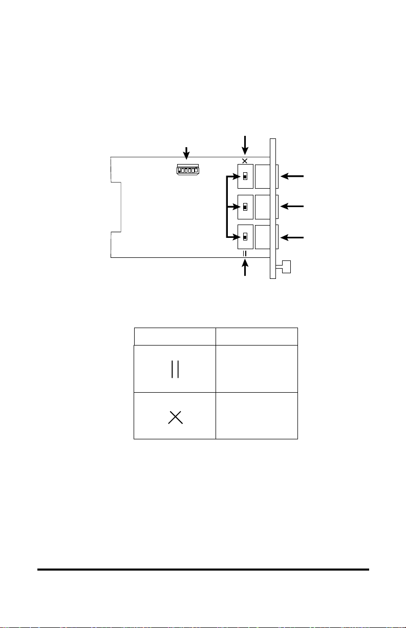
When setting the MDI-II/MDI-X switch, observe the positioning of the
following symbols:
•the parallel symbol (II) indicates a straight-through or parallel
connection (default)
•the cross symbol (X) indicates a crossover connection.
These two symbols are clearly marked on the printed circuit board.
Simply slide the switch in the direction of the appropriate symbol.
Set the MDI-II/MDI-X Switch
For each twisted-pair port, a switch is used to implement the transmit
and receive crossover functionality. The switch is positioned just
behind its associated RJ-45 connector. See the illustration below for the
location of the MDI-II/MDI-X slide switches.
3
MDI-II Position (default)
DIP Switches
RJ-45
RJ-45
RJ-45
RED
LLCF
LINK
AUTO
TX
MDI-X Position
Slide Switches
654321
SONR
The switch connects the transmit and receive signal pairs in either
straight-through or crossover configurations. The signal routing is as
follows:
Radiance 10Mbps Redundant Interface Line Card 13
4
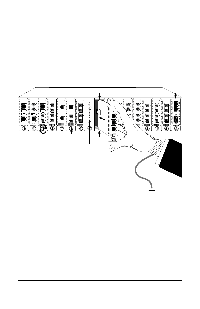
Install the Line Card
The Radiance 10Mbps redundant interface line card offers the ease of
plug-and-play installation and is hot-swappable. All cards must be
firmly secured to the chassis before network connections are made.
Follow the simple steps outlined below to install the line card.
NOTE: Proper grounding is recommended (i.e., wrist strap).
•Grasp the card by the front panel as shown.
•Insert the card into a slot on the chassis
making sure that the top and bottom edges of the card are
aligned with the top and bottom card guides in the chassis.
Do not force the card into the chassis unnecessarily. It
should slide in easily and evenly.
•Slide the card in until the top and bottom edges of the
front panel are flush and even with the top and bottom edges
of the chassis.
•Turn the thumbscrew clockwise until it is snug to secure the
card to the chassis. The card is now properly installed and
ready for connection to the network.
FX
PWR
RX
RX
LK
LK
M
M
FL
TX
TX
10/100
M
M
RX
LK
TX
FX
M
M
II
x
PWR
100 FD
RX
LK
T
X
TX
10/100
II
x
PWR
100 FD
RX
RX
LK
LK
T
X
M
M
FL
TX
TX
10/100
II
x
II
x
PWR
100 FD
100 FD
RX
RX
LK
LK
T
X
T
X
TX
TX
10/100
RX
LK
TX
FX
M
M
II
x
PWR
100 FD
RX
LK
T
X
TX
10/100 MGT-10
LK
AT
C
O
N
S
O
L
E
1
PWR
A
B
R
ER
FX
PWR
RX
RX
LK
LK
M
M
FL
TX
TX
10/100
M
M
PWR
RX
RX
LK
LK
M
M
FL
TX
TX
10/100
FX
M
M
PWR
M
M
OC-12
R
XLK
LK
T
X
S
M
R
X
T
X
LX
LK
LK
PWR
1000BASE
S
M
SX
M
M
PWR
1000BASE
LK
LK
SX
M
M
LX
S
M
R
X
T
X
Card Guide
Card Guide Slot for Management Card
Thumb Screw
Blank Panel
IMPORTANT!
Tighten thumb screw
to secure each card firmly
to chassis before making
network connections.
FX
PWR
RX
RX
LK
LK
M
M
FL
TX
TX
10/100
M
M
FX
PWR
RX
RX
LK
LK
M
M
FL
TX
TX
10/100
M
M
PWR
M
M
OC-12
R
XLK
LK
T
X
S
M
R
X
T
X
PWR
M
M
OC-12
R
XLK
LK
T
X
S
M
R
X
T
X
PWR
M
M
OC-12
R
XLK
LK
T
X
S
M
R
X
T
X
PWR
M
M
OC-12
R
XLK
LK
T
X
S
M
R
X
T
X
R
X
T
X
LK
PWR
10 BASE
M
A
I
NAT
P
R
I
S
E
C
RESET
LK
AT
LK
AT
SEC
LK
AT
2
14 Installation Guide
Connect to the Network
A total of three connections must be made on the front panel when
connecting the line card to the network. Make sure that all cards are
firmly secured to the chassis before making network connections.
•Connect to the MAIN port.
The Radiance redundant interface line card provides one
shielded RJ-45 jack for 10BASE-T connections and supports a
maximum segment length of 100 meters over Category 3, 4 or
5 twisted-pair cable.
Refer to STEP 3 for MDI-II to MDI-X switch functionality.
Before making the proper twisted-pair connection, verify the
port configuration of the connected device.
If you do not know the internal wiring configuration of the
other device’s RJ-45 port, consult the product documentation.
5
•Connect to the PRIMARY port.
•Connect to the SECONDARY port.
The R711-11 and R712-11 provide two additional RJ-45 jacks
for 10BASE-T connections and support a maximum segment
length of 100 meters over Category 3, 4 or 5 twisted-pair cable.
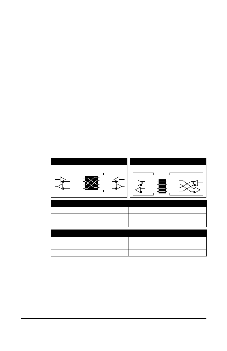
Embedded Parallel Function
A device that is wired straight through, needs one crossover connection:
If the cable is…
straight through
crossover
… the MDI-II to MDI-X Switch Setting should be
X
II
TD+
TD-
RD+
RD-
“redundant twister”
TP Port Configuration
Device with Straight Through
TP Port Configuration “redundant twister”
TP Port Configuration Typical Hub
TP Port Configuration
TD+
TD-
RD+
RD-
Embedded Crossover Function
MDI–XMDI
TD+
TD-
RD+
RD-
1
2
3
6
1
2
3
6
1
2
3
6
1
2
3
6
TD+
TD-
RD+
RD-
A device that is wired crossover, needs a parallel connection:
If the cable is…
straight through
crossover
… the MDI-II to MDI-X Switch Setting should be
II
X

Radiance 10Mbps Redundant Interface Line Card 15
Use the link (LK) LEDs on the front panel of the card to verify correct
segment connectivity. As you insert the cable into each port, the LK
LED illuminates provided there is power being applied to the chassis
and there is an active device connected to the other end of the cable
sending idle link signals.
100 BASE
redundant twister
“
MAIN
RESET
LK
AT
PRIMARY
LK
AT
SECONDARY
LK
AT
R
X
T
X
R
X
T
X
PWR
SW
100 BASE
redundant twister
“
MAIN
RESET
LK
AT
PRIMARY
LK
AT
SECONDARY
LK
AT
R
X
T
X
R
X
T
X
PWR
SW
100 BASE
redundant twister
“
MAIN
RESET
LK
AT
PRIMARY
LK
AT
SECONDARY
LK
AT
R
X
T
X
R
X
T
X
PWR
SW
100 BASE
M
A
I
N
P
R
I
S
E
C
RESET
LK
AT
LK
AT
LK
AT
SEC
PWR
SW
10 BASE
M
A
I
N
P
R
I
S
E
C
RESET
LK
AT
LK
AT
LK
AT
SEC
PWR
SW
100 BASE
M
A
I
N
P
R
I
S
E
C
RESET
LK
AT
LK
AT
LK
AT
SEC
PWR
SW
100 BASE
LK
AT
LK
AT
PWR
R
X
T
X
R
X
M
M
S
M
T
X
100 BASE
LK
AT
LK
AT
PWR
R
X
TX
FX
T
X
MGT-10
LK
AT
C
O
N
S
O
L
E
1
PWR
A
B
R
ER
100 BASE
redundant twister
“
MAIN
RESET
LK
AT
PRIMARY
LK
AT
SECONDARY
LK
AT
R
X
T
X
R
X
T
X
PWR
SW
100 BASE
redundant twister
“
MAIN
RESET
LK
AT
PRIMARY
LK
AT
SECONDARY
LK
AT
R
X
T
X
R
X
T
X
PWR
SW
100 BASE
M
A
I
N
P
R
I
S
E
C
RESET
LK
AT
LK
AT
LK
AT
SEC
PWR
SW
LK
AT
2

16
User Guide
This section contains information regarding the operating features of your
Radiance 10Mbps redundant interface line card.
LED Operation
Several LEDs are visible from the front panel. These include the switchover
(SW), power (PWR), secondary (SEC), link (LK) and activity (AT) LEDs. There
are separate link and activity LEDs for each of the three ports (MAIN,
PRIMARY and SECONDARY). Refer to the table below for a description of
each.
The indication of each LED is as follows:
LED Label Color (Status) Indication
SW Amber (steady) SECONDARY port was the active
port at some point. This LED
functions in Dynamic Recovery
Mode (DRM) only.
PWR Green (steady) Power ON
SEC Green (steady) SECONDARY port is active
OFF PRIMARY port is active
(MAIN) LK Green (steady) Receive link present
(MAIN) AT Green (blinking) Receiving data
(PRIMARY) LK Green (steady) Receive link present
(PRIMARY) AT Green (blinking) Receiving data
(SECONDARY) LK Green (steady) Receive link present
(SECONDARY) AT Green (blinking) Receiving data

Radiance 10Mbps Redundant Interface Line Card 17
Reset Push Button
A small RESET push button is located on the front panel of the Radiance
redundant interface line card. When used in conjunction with the card’s SW and
SECONDARY LEDs and theAUTO DIP switch setting, this push button allows
you to effectively maintain or troubleshoot a PRIMARY link connection.
Because of its small size and recessed placement within the front panel, press
the RESET push button with the tip of a pointed object. Pushing and holding the
RESET push button has no effect. It is the act of pressing the push button that
causes a reset.
In the event of a PRIMARY link failure, pressing the RESET push button has
the following effects:
If theAUTO switch is UP The active port automatically reverts to PRI-
and RED switch is UP MARY when primary link is reestablished and
pressing the RESET switch clears the SW LED.
If the AUTO switch is The active port does not automatically revert to
DOWN and the RED switch PRIMARY when a primary link is reestablished.
is UP Pressing the RESET switch clears the SW LED
and the SECONDARY LED and forces the
PRIMARY port to be the active port. If the
SECONDARY link is disabled, it reverts to the
PRIMARY if the PRIMARY has a good link.
If there is only a SECONDARY link, then the SW
and SECONDARY LEDs remain lit and pressing
the RESET switch has no effect.
If the RED switch is DOWN The card operates in Network Select Mode
(NSM). The RESET push button toggles the
active link between the PRIMARY and SECOND-
ARY ports. Note that the SW LED remains off
during Network Select Mode (NSM) operation.
18 User Guide
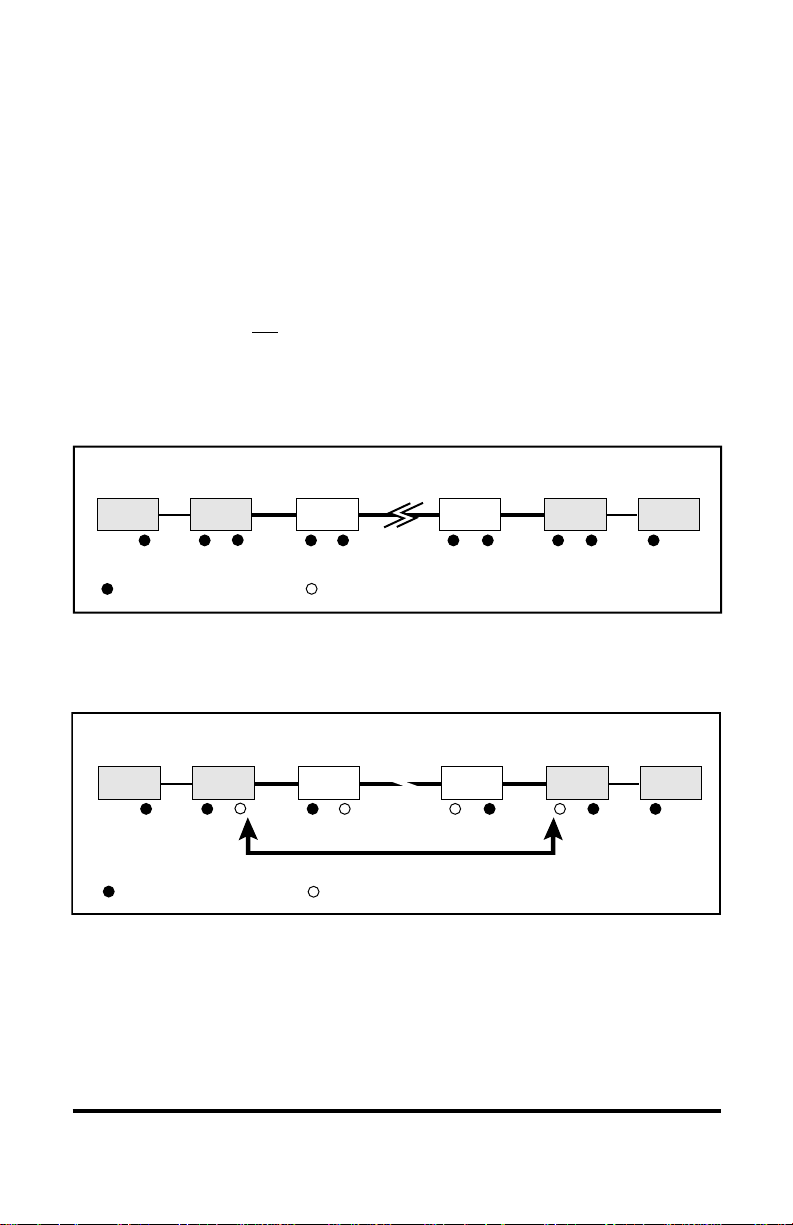
Link Loss Carry Forward (LLCF)
The Radiance 10Mbps redundant interface line card has been designed with
Link Loss Carry Forward ability for troubleshooting a remote connection. The
card is shipped with LLCF disabled.
When LLCF is enabled, the ports on the card do not transmit a link signal until they
receive a link signal from the opposite port. For example, if LLCF is enabled and
two redundant interface line cards are connected with nothing else connected to
them, the Link LED is not lit. When a valid link is established, a complete connec-
tion is accomplished.
The diagram below shows a typical network configuration using Radiance
redundant interface line cards for remote connectivity:
If the connection breaks, or the remote device fails, the card carries that link loss
all the way to the switch/hub which generates a trap to the management station.
The administrator can then look at the card to determine the source of the loss.
Management
Station Management
Station
Switch/Hub
w/SNMP Switch/Hub
w/SNMP
Redundant
Line Card Redundant
Line Card
Remote
up to 100m
LED lit = established link LED unlit = no link
Management
Station Management
Station
Switch/Hub
w/SNMP Switch/Hub
w/SNMP
Redundant
Line Card Redundant
Line Card
Broken
Remote
Cable
Link Loss Carried
LED lit = established link LED unlit = no link

Radiance 10Mbps Redundant Interface Line Card 19
Switch On No Activity Received (SONAR)
The R712-11 is designed to protect a network from failure that would prevent
data from reaching its destination. With SONAR enabled, the card monitors the
active port for loss of data activity, as well as loss of a valid link. SONAR
enables the redundant line card to automatically change its active port to its
backup when the following two conditions occur:
•No data activity is detected on the active port for two (2) seconds.
• Data activity is detected on the backup port.
To switch active ports, the backup port must have data activity within the two-
second time-out period when the active port lost activity. If both ports have no
activity, the port that receives data activity first becomes the active port.
The active port is switched immediately if it loses its link and the backup port
has a link.
To properly activate SONAR, make sure that the following switches are en-
abled:
1. RED switch. This sets the redundant interface line card to operate in
Dynamic Recovery Mode.
2. LINK switch. This allows link signals to be sent out both ports.
3. SONAR switch.
The settings of the other DIP switches do not affect SONAR operation. How-
ever, SONAR will override the Auto Restore Primary Circuit (AUTO) switch. If
both SONAR and AUTO are enabled, the active port will not automatically
revert to the primary port (after switching to the secondary port) if the primary
port has link but no activity. Data activity on the primary port must also be
detected during the two-second time-out period before the active port reverts
back to the primary port.
NOTE: The R712-11 is shipped with SONAR disabled. In addition to the
hardware switch setting, SONAR can be enabled via console commands or
through WebBeacon or NetBeacon management software (version 2.0 or later).
Refer to the Radiance Command Line Interface Reference Guide,
NetBeacon Element Management Software Installation & User Guide or
WebBeacon Software Installation & User Guide for software instructions.
20 User Guide
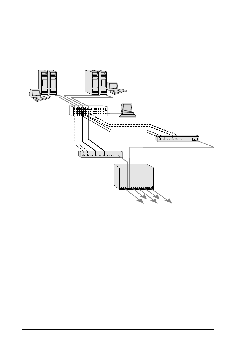
Topology Solution
Enterprise Switch
10Mbps Switch
Secondary Link A
Secondary Link B
PC running Network
Management Software
Primary Link A
Primary Link B
10Mbps Switch
Servers with
10Mbps NICs
Server Cluster A Server Cluster B
Radiance R5000 Chassis
with Redundant
Line Cards
This manual suits for next models
1
Table of contents


