Meyers Manx Kick-Out Traditional Manual
Traditional
Traditional Traditional
Traditional “Kick
“Kick“Kick
“Kick-
--
-Out”
Out”Out”
Out”
Build Instructions
Build InstructionsBuild Instructions
Build Instructions

Thank you for purchasing one of our new Kick-Out Manx’s. After being
out of production for nearly 30 years, we have reintroduced the world famous
Classic Manx – signature series, introduced the new Manxter 2+2 and Manxter
DualSport, and now the newest Kick-Out – traditional and Kick-Out S.S. Although often
copied, the fact remains that the Meyers Manx became the benchmark for all
others.
The Manx’ tremendous universal appeal both on and off the street has
propelled it into an astronomical orbit. Well known around the world, our cars
have reached as far as Europe, Australia, Asia and South America. When most
people talk about their fiberglass dune buggies, they commonly (and often
times) misrepresent them as a Meyers Manx. Why is that? As misguided as
some are, they immediately recall the most famous of buggies ever built and
desire to claim some of the history, nostalgia and quality that has been the
core of the Meyers Manx heritage.
As the best Meyers Manx ever, this Kick-Out kit reflects a 45 year legacy of
constant design improvement, with vastly increased accessibility to both
mechanicals and storage; it still embodies the original look that once
popularized the dune buggy worldwide. The following build instructions borrow,
in part, from the earlier Signature Series Manx kit, as the body mounting has
never changed (the pictures with the photos). The newer Kick-Out sequence of
steps # 1 - # 6 (the pages with of line drawings) must be followed exactly, as the
placement of the hood dictates the fit of the cowl to hood for the whole world
to see.
The Kick-Out Manx that you have purchased will potentially become a
collectible in that this will possibly be my last buggy design, hence the name -
Kick Out:
A surfing maneuver one makes at the end of the ride where he goes up and over the
A surfing maneuver one makes at the end of the ride where he goes up and over the A surfing maneuver one makes at the end of the ride where he goes up and over the
A surfing maneuver one makes at the end of the ride where he goes up and over the
wave to finish with a bit of style and grace.
wave to finish with a bit of style and grace.wave to finish with a bit of style and grace.
wave to finish with a bit of style and grace.
As in all of the Meyers Manx collection of cars the Kick-Out has the
unmistakable lineage of being hand-crafted and is the manifestation of
integrity, ingenuity and heritage. Remember: “
““
“I
II
If it doesn’t say Meyers, it’s not
f it doesn’t say Meyers, it’s not f it doesn’t say Meyers, it’s not
f it doesn’t say Meyers, it’s not
really a Manx ”
really a Manx ”really a Manx ”
really a Manx ”
Thank you for your patronage!
Bruce Meyers
Pan Shortening
By David Helland - Club Member #50
The VW Bug combines a body shell and chassis to im lement a very rigid "monocoque" body. The VW is
not a true "monocoque" because the body can be removed by sim ly un-bolting it. The remaining chassis
is called the " an.” The an consists of a central steel tunnel with front and rear assemblies for attaching
sus ension com onents and a thin sheet metal floor late to form the bottom of the car. When the body is
removed, the central tunnel of the an is the only remaining structural com onent between the front and
rear of the chassis. The tunnel is not a com letely rigid structural com onent in that it will allow some
torsion to occur between the front and rear of the frame.
When shortening the an it is extremely im ortant to correctly weld the tunnel back together to restore
the structural integrity of the frame. When a fiberglass body is bolted to the frame it regains some of the
"monocoque" characteristics but it is not nearly as rigid as the original VW Bug. If the tunnel is not
correctly welded and strengthened, the car is very likely to break in half. A MIG wire-feed welder is
recommended for the welding; however, I have done the job by steel brazing with oxygen-acetylene gas.
An arc welder is not recommended because the material is so thin that an arc welder will just melt holes in
the metal. It is also very im ortant to kee the alignment of the frame intact. I always s end more time
measuring for accurate alignment than I s end welding.
The body is removed from the frame by first removing all the bolts from the channel under the outer edge
of the frame (an air owered im act wrench does this quickly). There are also four bolts that must be
removed the middle of the underside of the car that are just in front of the rear torsion bar housing. Then
remove the two bolts under the rear wheel wells that attach the body to the rear cast sus ension
members. There are also two bolts under the rear seat of the car that attach to the rear cast sus ension
members. The last two bolts are located in front of the gas tank and connect to the to of the front
sus ension beams. Before you can lift the body off, you must disconnect the steering shaft at the steering
box, remove the s eedometer cable, disconnect the heater box control wires, and all remove the wiring
that connects to the engine and the master brake cylinder.
The next task is to lift the body off the chassis. There are several ways to do this. The method I chose in
1966 was to hook a winch to the rafters of my dad's garage. I succeeded in breaking the rafter and
colla sing the roof of the garage onto the VW! It is better to get four hel ers, two 12 foot 2x6's, and four
saw horses. First, lift the front of the body off the frame and sli a 2x6 under the wheel wells and su ort
it on each side with saw horses. Then do the same thing at the rear of the car. When the body is high
enough in the air, the frame can be rolled out from under it. I recently removed a body by myself by
building a large wood frame and using a "come-along" to winch the body into the air.
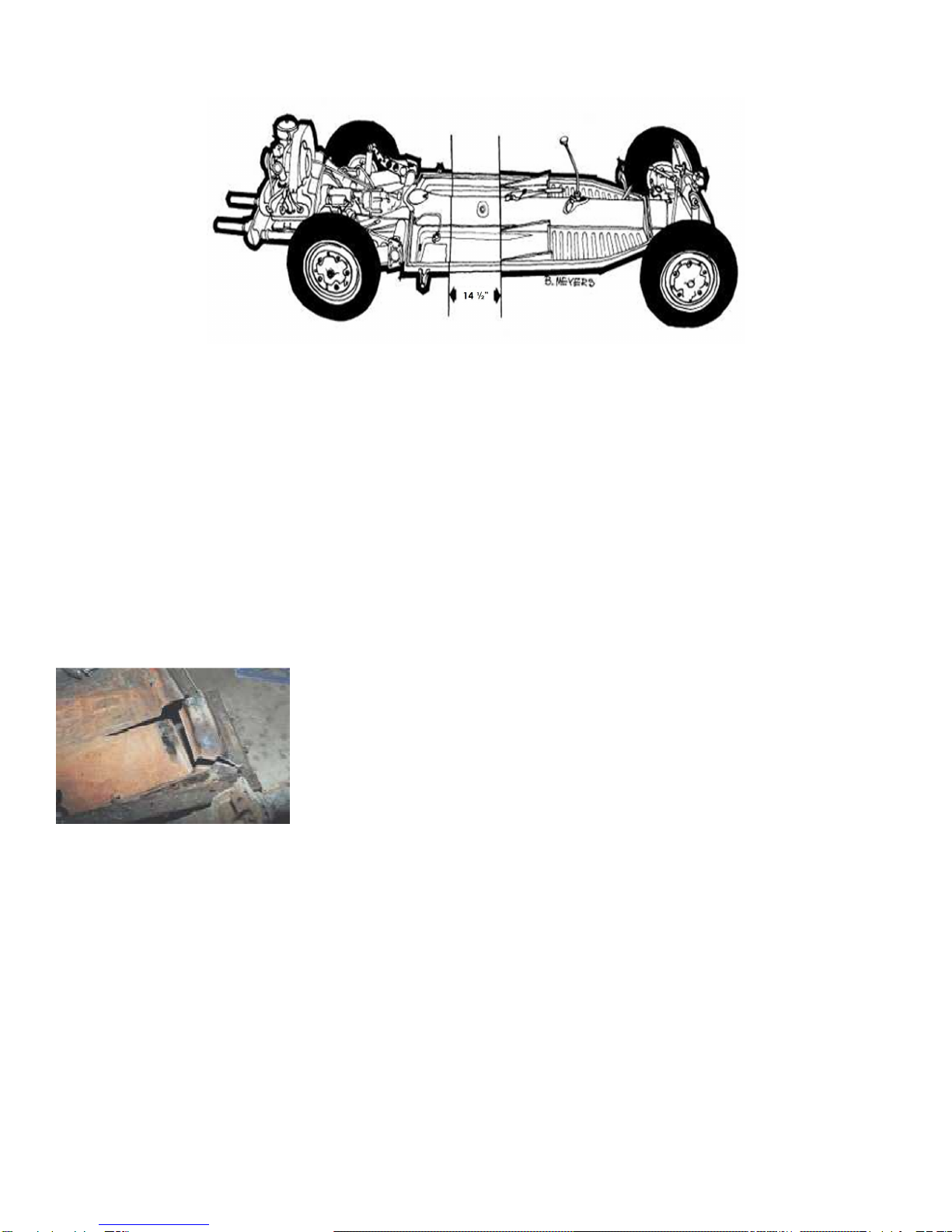
The location on the frame where the 14-1/2 inches is to be removed is
the straight section of the tunnel directly behind the emergency brake
handle on a line even with the rear of the seat su ort rails. When
examining the an it is obvious that because the sides of the VW an are
not arallel, the two halves are not going to exactly match when they are
ut back together. There are several ways to accom lish this feat. The
method that I am going to describe entails cutting out 14-1/2 inches
straight across the frame and then cutting darts out of the rear half to
make the two sides match.

Pan Shortening - Continued
Page 2 of 5
The frame now needs to be cleaned and re ared before shortening begins. The engine must be removed
because it is heavy and the an must be turned over to weld the bottom. O en the access hole at the
front of the frame between the front torsion bar tubes and remove the shift rod after detaching it from the
front of the transmission. Leave the front sus ension on the an to rovide necessary oints for
measuring and aligning the chassis. Clean the thick tar based sound deadening material from the entire
an so that the metal can be cleaned of rust and eventually ainted. The tar can be removed by using a
chisel and hammer, but an air chisel does this quickly. The tar can also be removed by heating the metal
near the tar to cause it to melt away from the metal (this is a stinky rocess). You must then remove the
rear brake drums and take out the emergency brake cables. Disconnect the hydraulic brake line at the tee
connector on the rear sus ension fork. Pull the brake line toward the front of the chassis by bending o en
the tabs that hold the line to the an. You will also have to remove the foot edal assembly to remove the
clutch cable and accelerator cable.
Now make crisscross measurements to verify that the frame is straight. Measure the distance from the to
of one front shock tower to one of the body attachment bolt holes in the o osite rear cast sus ension
mounts. Re eat the measurement using the other front shock tower and o osite rear mounting bolt hole.
The measurements should be the same within an 1/8 inch or so. We will re eat this rocess to guarantee
alignment after the 14-1/2 inches have been removed and the two halves are ushed together.
To make a tem late for marking the an section to be removed, cut a iece
of construction a er exactly 14-1/2 inches wide and about 30 inches long.
Lay the tem late on the floor an with one of the long edges just touching
the rear of the seat su ort rails. Use a silver drawing encil to draw two
arallel lines from the side of the an over to the bottom edge of the tunnel.
Re eat the rocedure on the other side of the an. Now lay the a er over
the tunnel about two inches behind the emergency brake bracket. Line u the
tem late so that the edges of the a er match the lines just drawn on the floor an. Use the silver
drawing encil to trace the edge of the a er over the tunnel at the front and rear of the a er tem late.
Once the an is clean, the next ste is to su ort it about 2 feet off the
ground so that it is erfectly level and convenient for cutting and
welding. To level the an, lace a bubble level on the straight art on
to of the tunnel in front of the shift lever and adjust the su orts front
and rear to center the bubble. The flat art of the tunnel just in front of
the rear access hole should also be level. The an must also be leveled
from side to side. This is accom lished by first lacing a straight edge
across the shock towers of the front sus ension and then adjusting for
side to side level. Then lace a straight edge across the rear cast
sus ension mounts to level the rear of the an.

Pan Shortening - Continued
Page 3 of 5
It is now time to cut using a reci rocating "sawsall" (an air owered cutting tool can also be used). It is
im ortant to not cut through the tubes that are located inside the tunnel
so s ecial care will have to be taken to locate and avoid them. Use the saw
to just barely cut through the front to corners of the tunnel just behind
the emergency brake. Stick a hacksaw blade through the cut to feel where
it is safe to cut. You can also shove a "snake light" into the rear access
cover to illuminate the interior of the tunnel. When you know where it is
safe to cut, go ahead and cut down the sides of the tunnel. The rear cut is
trickier because the tubes for the emergency brake are flush with the
sides of the tunnel. Be extremely careful to cut through only the tunnel and not through the tubes. During
the cutting rocess a hel er should a ly oil to the saw blade so that the job uses a cou le of blades
rather than a dozen. To remove the tunnel section you must saw along the bottom just flush with the
floor.
Don't cut u this iece because we will use it later to strengthen the tunnel. Use a disk grinder to cut a
slot in the tunnel so that the saw blade can be inserted.
Once the to of the tunnel has been removed, ut su orts under the middle of the car and cut the
sections out of the sheet metal floor.
It is best to cut the floor just inside the lines so that there will be a slight overla when the halves are ut
back together. Then use a straight edge to draw two lines on the remaining bottom section of the tunnel
and cut it out.
Before the two halves can be ushed together, the control tubes must be modified. At the rear access
cover, measure how far the clutch and accelerator tubes extend out behind the chassis and then cut them
away (not off) from the bracket that holds them to the tunnel. Remove the rubber grommet where the
fuel line sticks out of the rear transmission fork. When the halves get ushed together, these lines will be
ushed back and extended further out the holes from which they currently rotrude. Cut off the tubes that
are used to control the heater vents (unless you live in Canada). Use the sawsall with a long blade (12")
to reach into the rear section of the tunnel and cut the bracket that holds the gas line.
The emergency brake tubes require some s ecial consideration. What you do next de ends on whether
you can obtain or make shortened emergency brake cables. To make shortened cables you must obtain
new cable ends and have them swaged onto the shortened cables with a s ecial tool (this might be
accom lished at a yachting su ly com any).
If you can get shortened cables, you want to kee the tubes intact all the way u to the rear of the hand
brake cable o ening. Measure the distance from the forward tunnel cut to the front of the emergency
brake tubes. Mark this distance on the emergency brake tubes from the rear tunnel cut and sever the
tubes at this oint. Use the sawsall to cut the bracket inside the tunnel just behind the emergency brake

Pan Shortening - Continued
Page 4 of 5
brake lever hole and then remove the short sections of the tubes. Then ut a hose clam around the front
of the remaining emergency brake tubes so they will come together just behind the brake handle when
the an halves are shoved together.
If you cannot get shortened cables, the full length cables will be used and coiled u inside the tunnel. In
this case cut the emergency brake tubes just behind the front tunnel cut leaving the short section
attached under the rear of the brake handle. Next cut the emergency brake tubes about eight to ten
inches inside the rear an section and remove the loose ieces of tubing. Use the sawsall to enlarge the
rear tunnel access hole (not larger than the size of the cover late) so that it is ossible to get your hand
in there later to coil the cable and ut on cable clam s.
It is now ossible to ush the two an halves together. Kee the halves well
su orted so that they do not fall and bend the tubing. While ushing the
halves together, carefully ull the clutch, accelerator, and fuel lines out of
their res ective o enings. When the halves are together, check for any
mismatches that may need to be ground off with a welding grinder. It is
now time check for alignment again. Use the bubble level to adjust the to
of the tunnel at the front and rear as was done earlier.
Level the front of the chassis by using the straight edge across the to of the front shock towers. Level the
rear of the car using a straight edge across the rear cast sus ension mounts. Make the crisscross
measurements to verify that the chassis is straight.
Once the halves are tightly together and aligned, the welding rocess can begin. Tack weld the to center
of the tunnel and then the straight sections of the tunnel sides where they are evenly matched. Now use
an oxygen-acetylene torch to heat the mismatched sections and beat them into lace with a hammer.
Alternate between welding and heating with the torch until the tunnel is com letely welded on the to
side. There may be u to 1/2" ga where the two floors meet at the bottom edge of the tunnel. This will
require some extra heat and a 5 ound hammer to get the edges close enough to weld. Now turn the
chassis over and weld the bottom edge of the tunnel together.
The thin sheet metal floor can now be welded; however, a dart must be cut out of the rear corner before
the outside edges of the an will come together. Draw a line from the rear outside corners of the rear an
sections down along the inside radius of the corner to the bottom of the floor an. Then extend the line
straight and arallel to the outside edge forward to the cut between the halves. Use the sawsall to cut
along this line so that the rear corner is loose but not cut all the way off. Now fold the loose corner in until
There should be no more than 1/16 inch se aration at the tunnel joint. If
there is more than that, slide the halves a art and use the welding
grinder to remove excess metal. At the corners there will be u to 1/2"
mismatch due to the difference in the sha e between the front and rear
halves. We will heat the corners with a torch and bend them into lace
during the welding. Put the halves back together and re- measure. The
halves can be ut together under tension by using i e clam s between
the hand brake hole tension by attaching a "come-along" under the an
from the front sus ension to a chain attached to the rear forks.

Pan Shortening - Continued
Page 5 of 5
the outside edges of the an match. Use the silver encil to draw a line on the overla ed ortion of the
rear section. Pull out the loose corner and cut off the excess material at the marked line with tin shears.
Now fold the loose corner back in lace; clam it; and weld it.
I find cleaning the an before ainting is best accom lished with a heavy duty wire cu brush on a welding
grinder (sand blasting is o timum). Painting the whole an with POR-15, a rust inhibiting rimer and
finishing it with Rustoleum or other enamel aint is recommended. Finish the whole rocess with
Rubberized undercoating on the bottom.
To strengthen the tunnel weld, cut one 1-1/2 inch wide stri from the
removed tunnel iece and weld it over the to of the tunnel weld. If the
an has slots next to the emergency hand brake for heater controls,
these slots must be welded shut and strengthened. Cut the remaining
iece of the tunnel lengthwise into 1-1/2 inch wide stri s. Weld one stri
on each side of the tunnel on the vertical surface just below the hand
brake o ening. The cut narrow stri s and weld them over the heater slots
and to the u er edge of the stra s that were just welded into lace.
The last detail is to shorten the clutch, accelerator, and fuel lines that are
sticking out the rear of the chassis. Use the measurements for correct
length that were made before the chassis was cut in half. Re-install the
fuel line grommet to kee it from rattling and braze the clutch and
accelerator cables tubes to the edge of the an just under the rear access
cover. Don't forget that the shift rod must also be shortened 14-1/2
inches. When you shorten the rod, scribe a horizontal line on the rod
before you cut it to be sure that the two halves go back together without
any twist. Install a new nylon shift rod bushing inside the tunnel just
behind the shifter o ening before utting the shift rod back in lace.
From manufacturing, the Manx body will have some sharp edges.
Using 80 grit sandpaper on a rubber block or similar, sand the inner
and outer fender edges of the Manx body. Do not hand sand the
body edges.
Hold the block at approximately a 30 degree angle. By sanding the
glass in this manner, the gelcoat will not chip or crack along the edge.
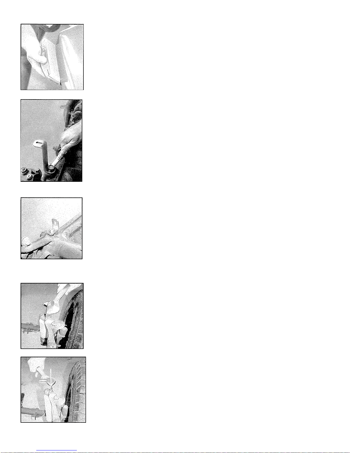
Front Body Mounts
Needed: Front Body Mounting Hardware # 251
Place the galvanized washers over the original VW mounting post on
the front suspension. Place the z-bent front body support over the VW
mount as shown. Note that the slotted hole is at the top of the mount.
On some suspensions, this threaded mount will be taller than the
bracket and washer. It may be necessary to use multiple galvanized
5/8” diameter washers as spacers in order for the bolt to hold the
bracket in place.
Position the brackets and finger tighten the bolts for now.
Roll Bar and Rear Body Mounts
Needed: Roll Bar Assembly Hardware # 154
This bracket doubles as a body mount and roll bar mount. Mount the
angel brackets using a washer and 3/8x5/8 bolt in to the cast torsion
body mount. If there is a broken off bolt in this mount, drill and tap to
accept the new bolt.
Repeat this procedure for both sides.
Finger tighten the bolts for now.
Side Body Mounts
Needed: Rear Body Mounting Assembly Hardware # 250
The following steps need to be repeated on the LEFT and RIGHT sides.
Remove the rear shock bolts. In order to make removal of the shock
bolt easier once the Manx is built, install the bolt from the outside to the
inside of the shock mount.
Sandwich the rear body mount bracket between the shock and the
shock mount and tighten the nut. With an adjustable wrench, twist the
plate about 30 degrees CCW for the right side and CW for the left side.
As a reference, the twisted bracket should line up with the spring hole.
Once the brackets are finished, tighten the shock bolts to keep the
brackets from rotating.

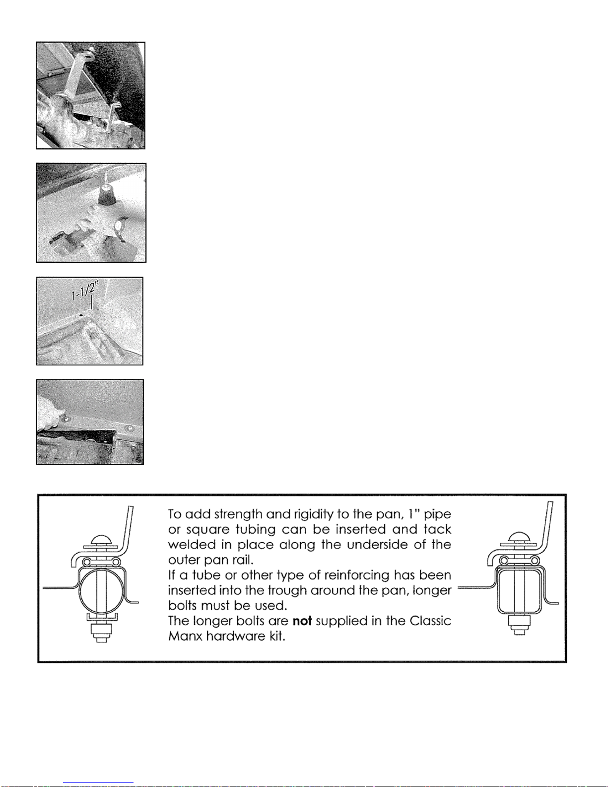
Floor Pan Gasket Placement
Needed: Stock VW floor pan gasket or truck cap foam
insulation, contact cement, scissors.
The floor pan gasket is fitted to the perimeter of the pan where
the pan meets the body. In the corners, dart the gasket as
shown.
Apply contact cement to the perimeter of the pan and on the
bottom of the gasket. Once the glue has tacked up, press the
gasket in place.
As an option, pickup truck camper foam for use between the
rails of the bed and the camper topper can be used. Various
thicknesses and widths are available at home improvement
stores.
Body Mounting
Needed: 2 persons, one Manx body, one pan.
With one person on each end of the body, lift and carry the
body over the pan.
Lower the body down and assure that the inner lip captures the
pan. Cut short wood sticks to jam between the tunnel and the
body. These will force the body outwards for a good fit before
drilling the body mounting bolts.
When the body has been properly seated, the front mounts will
need to be bent slightly forward.
This is accomplished by hitting the mounts with a hammer. Be
careful not to hit the body with the hammer.
When the body has been tightened down and the front mounts
brackets are positioned correctly, drill two 3/8” holes using the
bracket holes as guides. These holes will be used dually for the
fuel tank hold downs as well as front body support.
Do not put bolts through the holes. Placement of the tank will
occur later in the assembly process.
Once the body mounts have been adjusted with the hammer,
the upper angled flange should be parallel to the fiberglass as
shown.
When satisfied with the fit, have a helper hold the body in place
while holes are drilled for the body mounting hardware. Using
the original body mounting holes as guides, drill eight 5/16” holes
on each side of the body from the underside.
If a pan of different manufacture (such as the Berrien chassis) is
being used, drill one hole 1- ½ inches from the rear corners. From
there, mark the remaining locations for holes at 7-1/4” center to
center intervals.
Place a washer on the button head bolt and push through the
body mounting holes.
Put the VW square washer on the underside of the bolt and
apply the NYLOC nut.
Finger tighten bolts.

TOOL LIST:
1. You will need 4 spring clamps (or “C” clamps)
2. Drill motor
3. 3/16” dia. drill bit
4. 3/8” dia. drill bit
5. Countersink bit
6. Masking tape or packaging tape
Step #1 – Two molded in dimples will be found near the lower front edge of the hood. Drill
these with a 3/8” dia. bit. Install the slip-hinge inside the hood (opposite of the gelcoated
side). Secure the hinge to the hood using the two 3/8” x ¾” socket head bolts, nuts and
washers. With both leafs of the slip-hinge joined together, place the hood on the car
carefully positioning the hood well back, snug between the front fenders. Working under the
car, the loose leaf of the slip-hinge should be swung upwards against the body. Drill
upwards two 3/8” dia. holes. The two flat head socket bolts are used here necessitating
countersinking the gelcoated side of the fiberglass. This provides a smooth surface as
protruding bolt heads would wear holes in those spare plastic gas cans, tool bags or
whatever might be stored here.
Step #2 – The placement of the hood
dictates the placement of the cowl.
Place the cowl under the rear edge of
the hood. With proper fit, tape together
firmly. Swing up and out of the way.

Step #3 – Place the dashtub inside the
body with clamps.
Step #4 – Place the dashframe inside
the body, Clamp to dashtub.
Step #5 – Swing hood/cowl back down
to body/dashframe.
Step #6 – Rotate dashframe to fit to the
cowl. The cowl will not cover the entire
top of the dashframe by approximately
¼” still revealed.
Step #7 – With successful alignment,
using a drill Motor and 3/16” dia. drill-
bit, drill upwards through seven pre-
drilled holes in the dashframe and
fiberglass cowl. Note: The cowl ends
do not reach around and beyond the
centerline holes of the dashframe for
windshield mounting.

Using the Steering Column Assy – Part #K-325,
the column is assembled as shown to the left.
Step #11 – You will find the dash tub fits
between the lower bar of the dash frame
and the upper edge of the body’s front
crosspanel. Three 1/4/20” x 1 ¾” long hex
bolts, nuts, and washers (Dash Tub Assy – Part
#K-237) are to be used in ¼” holes drilled
down through the dash tub and the lower bar
of the dash frame. These are to be placed
near each end and one in the middle of the
dash frame. The six 10/32” x 1” truss head
bolts, nuts and washers are to be spaced
approximately 6” apart across the front of the
tub.
Step #8 – Using the 3/8” dia. drill-bits. Drill
through Dashframe holes and through the
body. Using the four 3/8” x 1” hex head bolts,
nuts and washers (dashframe assy Part # 236).
Place the bolts and washers on the outside
against the fiberglass and the nuts on the
inside of the dashframe and body after
painting.
Step #9 – Remove hood, cowl & dash tub
from car.
Step #10 – Cut a small panel of plywood or
heavy cardboard 24 ½” long x 6”-8” wide.
One of the 24 ½” long edges should be a
straight edge. Measuring 10” from each end
cut a notch 4” deep. Cut a small 5/16”
corner notch at either end of the straight
edge. This small corner notch is to be placed
on the end of the steering shaft at the
steering box. Sighting or eyeballing down the
straightedge will show you where to drill the 1
¾” diameter hole in the pedal bulkhead. If
this method seems like overkill, it does insure a
correctly placed hole every time.

Step #12 – Dashboard Assy – Part #K-234
Lifting the cowl up slightly, the dash is fitted
under the top edge of the cowl. The ends of
the dash will reach around the ends of the
dash frame to butt the ends of the cowl at
the dash frames centerline. Using the 7 holes
in the cowl as a guide, drill down through the
dash which is just below. Using the seven
10/32” x 1” long bolts, nuts and washers,
secure the top of the dash and cowl to the
dash frame. The three ¼ /20” bolts are
temporarily removed at the bottom of the
dash frame to drill and reassemble the
bottom of the dash.
Step #13 – Windshield Assy – Part #K-255
With the small top slot facing forward on the
windshield frame, the two 6” long bars with
studs attached must be trial fitted. That is, slid
up into the open ends of the windshield
frame. Once satisfied as to their final
positioning, with drill, clean out any fiberglass
obstructions in the four holes at the cowl
ends. Carefully transfer from windshield, the
bars to the awaiting holes at the cowl ends.
Loosely attached, you and a helper should
lower the windshield down onto its new
home, sliding the bars up into the windshield
frame. The “H” rubber must be shipped into
place between the windshield and the body
before a rubber mallet might be used to help
bonk it down before tightening the four 5/16”
nyloc nuts.
Hood Latch Installation:
Step #14 – Next, the rubber hood latches can be installed using Hood Assy – Part #mxtr-1004. This
is a two-part assembly using the six 10/32” x ¼” button head socket bolts. The smaller anchor post
part uses only one bolt with a locating pin on its underside. Place the anchor post on the cowl
approximately one inch from the rear edge of the closed hood and approximately one inch
above the upper rear corner of the front fender. Note, the anchor post’s small hooked upper
edge enabling the rubber catch from slipping off the anchor post. Note also, the nearly hidden
locating pin underneath to keep the post from revolving around while under pressure. Mark this
spot to drill a 3/16” dia. hole for the locating pin. Placing the anchor post with pin in this hole,
align for placement and drill the second hole for the 10/32” x ¼” button head socket mounting
bit. Repeat this process on the opposite side of the car. Next, after hooking the handle of the
catch over the anchor post, stretch it slightly with the hood solidly closed, and with proper
alignment insert the 3/16” dia. drill bit in one of the two holes and drill through, bolt it down and try
the rubber catch for alignment insert the 3/16” dia. drill bit in one of the two holes and drill
through, bolt it down and try the rubber catch for alignment. If there is a good result, drill the
second hole and finish bolting the rubber latch to the hood, both sides.

FUEL TANK INSTALLATION:
Any VW Bug gas tank will fit the same space provided, but I recommend the following: In
1968 a little door appeared just forward of the passenger door on all VW Bugs. This little door
opened to a filler cap screwed to a neck within a rubber hose connected to the fuel tank
under the hood. Save all this stuff, it can be shortened some and used along with the four
hold-downs that clamp the tank into the body. If unavailable, four large fender washers will
also work under the four boltheads. A small diameter tube may be found at the opposite
end of the tank from the filler pipe. This can be used as a breather tube by running a small
plastic hose from this upwards, crossing to the other side of the car under the windshield,
down and out through a small hole down the body and out through another small hole
drilled in the floorpan to be pointed at the ground – works!
FUEL TANK ALTERATION:
Warning! This is a potentially dangerous process if the following procedure is done on a used
gas tank. The only answer to the interfering headlight well, bumping into the gas tank, was
to remove the interfering gas tank. Not to worry! Most old VW tanks that look great are
rusted out around the drain hole. Check it out. If you still want to use an old gas tank, plug
up all outlets, fill the tank with water, prop it up so the only air space is up in the intended
area of the front corner driver’s side before welding on the tank – whatever, it’s your choice.
We can supply you with a new altered tank or you may use the following directions on a
new tank.

ROLL BAR INSTALLATION:
One of the most glaring mistakes in the building of a Meyers Manx dune buggy is the bad placement
of the roll bar. The slight sloping back of the windshield (18° from vertical) is to be repeated in the roll
bar – an elemental basic of the cars design. The fact that we have pre-drilled the roll bar holes in the
body does not insure proper placement, except for this leaning back angle. The other element of
misplacement is the not so perfect matching alignment of its top to the top of the windshield. As one
walks toward a buggy that has its roll bar top edge cock-eyed to the windshields top edge, the
whole car appears twisted or distorted. So, we have decided to pre-drill only the roll bar holes on the
driver’s side. Using Roll Bar Assy – Part #154, you attach the roll bar to these holes only attaching the
small “L” brackets to the torsion housing first, then eyeball or level the roll bar to match the top of the
windshield, drill and secure the roll bar’s other side to complete the installation.
For a maximum strength installation, the “L” brackets should be bolted down into the unused
body mounting holes found nearest the outer ends of the rear torsion bar housing. The remaining
vertical end of the “L” bracket should fit against the outside of the body, the intention being to pass
a bolt through it, the fiberglass and the lower weldment bracket of the rollbar. Most important, this
ties the rollbar to the chassis. The upper weldment should be bolted to the body side panel, using the
3/8” flat washers against the outside of the fiberglass body.
Because of certain uncontrollable variables in bodies and body mounting, the “L” brackets
become “L”aughable and may need re-bending or re-drilling. Do not use the sheet-metal floorpan
as an attachment point.
HOOD EMBLEM:
The last and final touch to the hood is the application of the Meyers Manx hood emblem on
the small surface created for it. A dry run for placement is recommended. The lower edge of the
emblem should not be placed below or beyond the top or beginning of the small radius on the
bump just below the emblem. Before removing the protective backing, hold the emblem in position
and see if it rocks to and fro. If it does, use a marker and outline the emblems placement. With
masking tape, mask outside of the outline for protection. Because the plug used to make the hood
mold was so highly polished and buffed, this small bump became slightly rounded, it’s once flat
surface becoming rounded off. A small block with course 16-36 grit sandpaper can be used, or a
small 1½” – 2” disc sander in your drill motor, gently flatten the surface, grinding into the gelcoat until
its flat. Check often with a small straight edge. 3-M emblem adhesive will insure a good grip being
sure to follow directions to the letter. Acetone or fingernail polish remover will remove the lines from
the marker pen.
OPEN HOOD:
When open, the hood is designed to stand vertically, leaning against the backside of the front
bumper. The hood is shiny and smooth, so is the polished stainless bumper or chromed nudge bar,
whichever you have purchased. Gently coming to rest, there is little to show where they touch, but
eventually this will mar the finish. Two small pieces of rubber or sponge-faced tape applied to the
backside of the bumper will make a soft protective resting place for the hood.
HEADLIGHTS:
The headlight mounting pads are to be drilled with a ½” diameter drill bit. Since the headlights are to
be moved about for final adjustment, a tightly fitting hole won’t allow this. Once drilled through,
wobbling the running drill bit this way and that provides the necessary slop for headlight adjustment.

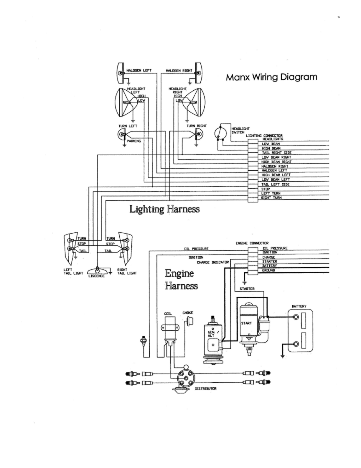
WIRE MANAGEMENT:
Wiring the
Kick-Out
is a simple job whether an aftermarket harness or the included diagram is
used. The attached wiring diagram was developed by the late David Helland. It is an excellent
model from which to wire your
Kick-Out
.
A six-foot plus grey color 1¼” diameter plastic tube is included in the
Kick-Out
kit. Intended to
carry the wire from the front to the rear of the car, it is to be fitted up under the driver’s side fender.
The 2 electrical clips provided need their holes to be enlarged to 3/8” diameter, as these clips are to
be secured by the upper bolts of the dash frame and roll bar. A 1” diameter hole is to be drilled
adjacent to the front of this tube through the body into the dash tub area to complete the electrical
passage.
Note: To aid in the wiring process, run a lead wire down through the hole in the body and pull
it through the rear exit hole. Make a loop on the end of the lead wire that the loom can thread
through and tape the loom to the wire. Pull the loom through the tube using the lead wire as a
guide.
*See supplemental wiring diagram on the following page.
OPTIONAL ACESSORIES FOR THE TRADITIONAL
Kick-Out
:
SHOWN ON THE COVER PHOTO OF THIS MANUAL
Front & Rear Polished Stainless Bumpers
Polished Stainless Roll Bar
Aluminum Skid Plate
Aluminum Bash Plate
AVAILABLE, BUT NOT PICTURED
Vented Sidepods
-
Hardtop (1-piece or 3-piece)
Rear Deck Lid
Wind Wings (Clear or tinted polycarbonate)
COMING SOON
Mini Soft Top
Side Curtain Kit
Spare Tire Kit


OPTIONAL PARTS INSTRUCTIONS:
VENTED SIDEPOD ASSEMBLY INSTRUCTIONS
The sidepods are to be slipped up under the buggy’s fender, not to be slipped in
between the body and the floorpan, but under the floorpan – along the bottom. At the
outset, three of four body bolts should be removed from each side of the floorpan, to be
drilled down through and replaced later (possibly with longer bolts).
When starting out, a floor jack with a wooden block on top, better yet, two jacks and
the help of a friend will reduce frustration. A bolt at each end, up under the fender, finishes
the job.
The sidepods are not intended to be water or mud-proof, but lots of clever folks have
made a waterproof compartment by cutting a reach-through access hole from the inside of
the car. If one does this, remember to radius the inside corners of the cutout to reduce the
possibility of stress cracks later. The upholstery shop has “pinch welt”, a plastic edge trim for
covering the raw fiberglass edge of the access hole.
Much scrutiny of late Ferrari’s and Lamborghini’s air inlet ducts lays bare the source of the
protective screens that reside in these air ducts, as this material is nothing more than ½”
hardware cloth, the most common of barnyard materials! On smaller air inlets those
inventive Italians sometimes placed the wires of the screens at a 45° angle to be extra
clever. Otherwise, the screens are placed in a north, south, east and west configuration
level to the earth… suit yourself. Closer scrutiny shows that the screens have been powder-
coated shiny black, looking fatter or thicker. You too could do this – I didn’t. Further
inquisitiveness provided a not so surprising insight into these super expensive cars. I found a
dazzling display of fabrication as an art form wherein the delicate frame that secures the
screen to the car was hand-formed and welded from numerous itsy-bitsy pieces – nary a
thought of simplification from its maker! I used epoxy. No doubt there could be other
suitable ways to attach these screens to the backside of the fiberglass sidepods, but the
following procedure worked for me and is simple and functional.
Fig 1. Working from the backside of the sidepods, the outer perimeter wall of the air-duct
opening must be thoroughly sanded using the coarsest of sandpaper (16-grit) and/or a small
disk or drum sander. Sand about an inch or more down from the opening edge as illustrated
by the shaded area in Fig 1.
This manual suits for next models
1
Table of contents


