MF&B Restaurant Systems EDGE 1830 User manual
Original Installation
Operation & Service Manual
(2C) Chassis, 2022
US Domestic
Retain This Manual for Future Reference
To Be Service by Authorized & Qualied Personnel Only
MF&B RESTAURANT SYSTEMS, INC.
119 ICMI RD, STE 300, DUNBAR, PA, 15431 USA
(1)888.480.EDGE
(1)724.628.3050
SUPPORT@EDGEOVENS.COM WWW.EDGEOVENS.COM
CD-941-407-3
EDGEEDGE 18301830
EDGEEDGE 2440, 32402440, 3240
EDGEEDGE 2460, 3260, 3260S2460, 3260, 3260S
EDGEEDGE 3860, 4460, 4460S3860, 4460, 4460S
EDGEEDGE 3270, 38703270, 3870

PROUDLY BUILT IN THE USA
MF&B Restaurant Systems, Inc.
119 ICMI RD, STE 300
Dunbar, PA 15431, USA
724.628.3050 (telephone)
724.626.0247 (fax)
www.edgeovens.com
Valued customer,
We thank you for the opportunity to provide you with, what we believe to be, the nest conveyor oven
available on the market today.
Our experience as pizzeria owners has given us the opportunity to improve on the conveyor oven in-
dustry. We imagined a better oven with a better bake, so we built one... for you. Thank you for your trust
and thank you for choosing EDGE ovens. May your business be blessed with success!
Sincerely,
Mark Bielstein,
President, MF&B Restaurant Systems, Inc.
Michael French,
Secretary & Treasurer, MF&B Restaurant Systems, Inc.
Please visit our website for additional information and documentation.
3133776 1312DL6500

Service policy
All service technicians of the EDGE Oven must read this summary and all warnings and cautions in the manual.
Any internal part(s) replacement or assembly and reassembly must be performed by qualied service person-
nel with a good understanding of mechanical, gas and electrical components. If diculties arise in locating a
qualied service person, please contact your EDGE oven distributor or MF&B for assistance in locating qualied
personnel to assist you.
All repairs on products within the warranty period must be PRE-AUTHORIZED by MF&B Restaurant Systems,
Inc., or an approved representative within the designated region. Unauthorized repairs will not be reimbursed.
Modications will void the warranty. Consult the WARRANTY POLICY within the Installation and Operation In-
structions for complete details.
If the product fails to function correctly—or if you need assistance, service, or spare parts—contact MF&B
Restaurant Systems, Inc.
Before contacting MF&B Restaurant Systems, Inc., try to duplicate the problem, and check electrical outlets and
gas supply lines to ensure that they are not causing the problem. When calling, please be prepared to provide:
• Supplier, model number, and serial number of your product.
• Complete description of the problem.
• Complete name, address, and phone number of your facility.
• For out-of-warranty repairs or spare parts orders, a purchase order (or credit card) number.
• For parts orders, the required spare or replacement part numbers.
If your product requires warranty, or non-warranty repair service, please call MF&B Restaurant Systems, Inc.
rst. A representative will assist you troubleshooting the problem and will make every eort to solve it over the
phone, avoiding potential unnecessary expenses and downtime.
In case a service call cannot be avoided, the representative will record all necessary information and may at-
tempt to coordinate the delivery of repair parts with a servicer in your area. Repair parts which are not used and/
or replaced parts should be returned to MF&B Restaurant Systems, Inc.
To aid in quick service and to accommodate the servicer providers needs, ensure the product is accessible and
that there is ample clearance for the product to be disconnected and rotated as needed.
Due to the size of the product and the size of the product parts, a servicer may require assistance with some
handling or maneuvering or this product or product parts. Please use care and correct lifting techniques.

Table of Contents
WARNING AND SAFETY INFORMATION ...............................................................i
SPECIFICATIONS ................................................................................................ 1
Export, Gas Conguration Data........................................................................................................1
North America, Gas Conguration Data ...........................................................................................2
Dimensions.......................................................................................................................................3
OVEN COMPONENTS.......................................................................................... 4
INSTALLATION INSTRUCTIONS .......................................................................... 5
Foreword ..........................................................................................................................................5
Tools & Equipment Required ............................................................................................................ 6
Stacking Ovens ................................................................................................................................7
End Plug Removal & Inspection .....................................................................................................12
Conveyor Drive System..................................................................................................................13
Standard Accessories.....................................................................................................................15
Finger Assemblies ..........................................................................................................................16
Collimating Panels..........................................................................................................................17
Restraint Cable...............................................................................................................................18
Final connections............................................................................................................................18
Valve Specications........................................................................................................................19
Manifold Adjustment .......................................................................................................................20
Air shutter .......................................................................................................................................20
First Firing / Test Firing ...................................................................................................................20
Warranty Activation.........................................................................................................................21
OVEN VENTILATION ......................................................................................... 21
Ventilation Requirements................................................................................................................21
Fire Suppression ............................................................................................................................21
DECOMMISSIONING AND DISPOSAL................................................................ 21
OVEN OPERATION ............................................................................................ 22
Oven Start-Up.................................................................................................................................22
Oven Shutdown ..............................................................................................................................22
Basics .............................................................................................................................................22
Menu System..................................................................................................................................23
Advanced Operation.......................................................................................................................24
PREVENTATIVE MAINTENANCE........................................................................ 27
SERVICE OPERATION....................................................................................... 32
SERVICE TOOLS & MATERIAL.......................................................................... 33
SEQUENCE OF OPERATION ............................................................................. 34
EDGE G2, Control Module Pinout ..................................................................... 36

WIRING DIAGRAM............................................................................................. 37
PART IDENTIFICATION...................................................................................... 38
GAS CONVERSION ........................................................................................... 39
Removing the Gas Train ................................................................................................................. 39
Replacing the Main Orice .............................................................................................................39
Replacing the Pilot Orice ..............................................................................................................40
Replacing the Gas Valve ................................................................................................................40
Installing the Gas Train ................................................................................................................... 40
Adjustment Air Shutter....................................................................................................................41
Gas Type Markings.........................................................................................................................41
TROUBLESHOOTING ........................................................................................ 42
Basics First .....................................................................................................................................42
G2 ‘DIAGNOSTIC’ Lamp ................................................................................................................43
G2 Control System Messages........................................................................................................44
PART FAILURE VERIFICATION.......................................................................... 47
Controls and assemblies ................................................................................................................47
TYPE-J THERMOCOUPLE CHART..................................................................... 50
Thermocouple Worksheet ..............................................................................................................51
PART LIST......................................................................................................... 52

EDGE Original Installation, Operation and Service Manual i
PREFACE
PREFACE
WARNING AND SAFETY INFORMATION
WARNING
Do not store or use gasoline, cleaning solvents, or any other material that may emit am-
mable vapors near this or any other appliance.
WARNING
Improper installation, adjustment, alteration, service, or maintenance can result in prop-
erty damage, injury, or death. Read this entire manual and ensure that you thoroughly
understand all instructions before installing, operating, or servicing this equipment.
WARNING
Keep the appliance free and clear of combustibles. Do not use aerosols within the area
of the operating appliance.
WARNING
Do not obstruct the ow of combustion or ventilation air to and from the oven. There
should never be any obstructions on or around the oven that could hamper the ow of
combustion or ventilation air to or from the oven. Any changes to the area where the
oven is installed must not aect the combustion or ventilation air to and from the oven.
IMPORTANT
Retain all shipping materials until you are certain that the oven has not been damaged
(either externally or internally) during shipment. Thoroughly inspect the oven on receipt
for both external and internal damage. It is solely the customer’s responsibility to report
any shipping damage to the freight company.
NOTICE
Oven installation, including electrical and gas connections, oven placement, and venti-
lation must comply with all applicable national and local codes. National and local codes
supersede the recommendations, requirements, and guidelines contained in the manual.
NOTICE
The purchaser of this equipment is required to prominently post instructions to be fol-
lowed should the user smell gas. This information shall be obtained from the local gas
supplier.
NOTICE
Installing any part(s) not provided by the Edge oven OEM shall void the warranty and
release the OEM from any and all liabilities.

EDGE Original Installation, Operation and Service Manual
ii
PREFACE
PREFACE
NOTICE
The oven electrical wiring diagram is located inside the control compartment.
IMPORTANT
US CUSTOMERS
Oven installation must comply with local codes or, if local codes do not exist, with the
National Fuel Gas Code, ANSI Z223.1/NFPA 54.
This appliance must be electrically grounded in accordance with local codes, or if local
codes do not exist, with the National Electrical Code, ANSI/NFPA 70.
IMPORTANT
CANADIAN CUSTOMERS
Oven installation must comply with local codes or, if local codes do not exist, gas oven
installation must comply with the Natural Gas Installation Code, CAN/CGA-B149.1, or
the Propane Gas Installation Code, CAN/CSA-B149-2, as applicable.
This appliance must be electrically isolated in accordance with local codes, or if local
codes do not exist, with the Canadian Electrical Code, CSA C22.2.
IMPORTANT
EXPORT CUSTOMERS
Oven installation must comply with local codes. This appliance must be electrically
grounded in accordance with local codes.
NOTE
This appliance and its individual manual shuto valves must be disconnected from the
gas supply piping system during any pressure testing of gas supply piping at pressures
exceeding 1/2 psi (3.5 KPa).
WARNING
Always check for leaks after making any gas supply piping connections or performing
any service on the oven.
NOTE
The installer of this oven must contact local building and re ocials concerning inspec-
tions and installation requirements of this oven and its ventilation system.
NOTE
Appliance is NOT to be cleaned with jets of water. End plugs and oven back are not to
be submerged.

EDGE Original Installation, Operation and Service Manual iii
PREFACE
PREFACE
IMPORTANT
NORTH AMERICA CUSTOMERS
OVENS EQUIPPED WITH CASTERS:
1. When this appliance is installed with casters, it must be installed with the casters sup-
plied, a connector complying with ANSI Z21.69 (CSA 6.16), a quick-disconnect device
complying with ANSI Z21.41 (CSA 6.9), and a mechanism to limit movement of the
appliance without straining the connector or its associated piping system.
2. Adequate means must be provided to limit movement of the appliance without de-
pending on the connector, quick-disconnect device, or associated piping to limit ap-
pliance movement.
3. The restraining device must be attached to the mounting eye located on the left side
of the oven base assembly.
IMPORTANT
EXPORT CUSTOMERS
OVENS EQUIPPED WITH CASTERS:
1. When this appliance is installed with casters, it must be installed with the casters
supplied, a quick-disconnect device, and a mechanism to limit movement of the ap-
pliance without straining the connector or its associated piping system.
2. Adequate means must be provided to limit movement of the appliance without de-
pending on the connector, quick-disconnect device, or associated piping to limit ap-
pliance movement.
3. The restraining device must be attached to the mounting eye located on the left side
of the oven base assembly.
WARNING
To prevent damage to the oven and personal injury or death, the voltage, phase and
grounding of the electrical supply must be inspected and veried prior to energizing.
WARNING
NORTH AMERICA CUSTOMERS
This appliance is equipped with a three-prong (grounding) plug and must be connected
to a properly grounded three-prong receptacle. This is to protect you from a possible
shock hazard.
DO NOT remove the grounding prong from this plug or use any form of adapter to plug
the appliance into a standard two-prong receptacle.
Use only the cord set supplied by the oven OEM, or a direct replacement cord set pur-
chased from the oven OEM. Other cord sets may present a re and/or electric shock
hazard.

EDGE Original Installation, Operation and Service Manual
iv
PREFACE
PREFACE
General cautions
!
WARNING Indicates conditions that could lead to injury or death.
!
CAUTION Indicates conditions that could damage equipment or property.
CAUTION Indicates conditions that may result in a burn injury.
General Warnings
Warnings indicate conditions or practices that could lead to injury or death.
Warnings related to the operating environment
!
WARNING To avoid a possible explosion, do not service the product in an atmosphere where explo-
sive gases or fuel vapors are present. Verify all gas valves are in the OFF position and that enough ventilation is
present to evacuate any unburnt gases.
Warnings related to electric shock
!
WARNING Electricity can seriously injure or kill. Disconnect the power cord for the electrical outlet
or lock out the service disconnect before servicing this equipment. Always ensure an earth ground is correctly
connected to the equipment. When troubleshooting live electrical circuits, use care and best practices to ensure
an electrical pathway is not completed through the body.
Warnings related to hot surfaces
WARNING Seriously injuries may occur from contact to hot surfaces. Allow adequate cooling time
of the appliance prior to service or maintenance. In situations where handling of the appliance or its parts is
unavoidable, use thermal protective gloves to protect the hands, wear long shirts and pants to protect arms and
legs. Do not attempt to “test” the temperature of surfaces by touch.
General Cautions
Cautions indicate conditions or practices that could damage the equipment or other correctly.
!
CAUTION To prevent possible damage, do not use sharp or hard objects on interface screen, use
only ngertips.
!
CAUTION Mobile RF communications equipment and high frequency LED lighting may aect the
performance of this equipment as dictated by FCC regulations.
!
CAUTION The power cord must be disconnected from the AC power before cleaning, maintaining,
servicing, or transporting.
!
CAUTION The gas supply line must be disconnected from the oven before cleaning, maintaining,
servicing, or transporting.
!
CAUTION There are NO parts of the oven that are designed to withstand impacts. Damage will re-
sult.

EDGE Original Installation, Operation and Service Manual v
PREFACE
PREFACE
Electrostatic discharge (ESD)
!
CAUTION Electrostatic discharge (ESD) can damage or destroy electronic components. Handle stat-
ic-sensitive components using safe practices.
!
CAUTION Assume that all electrical and electronic components of the appliance are static sensitive.
Electrostatic discharge is a sudden current owing from a charged object to another object or to ground. Elec-
trostatic charges can accumulate on common items such as foam drinking cups, cellophane tape, synthetic
clothing, untreated foam packaging material, and untreated plastic bags and work folders, to name only a few.
Electronic components and assemblies, if not correctly protected against ESD, can be permanently damaged or
destroyed when near or in contact with electrostatic charged objects. When you handle components or assem-
blies that are not in protective bags and you are not sure whether they are static-sensitive, assume that they are
static-sensitive and handle them accordingly.
• Always use techniques to protect personnel and equipment from electrostatic discharge. ESD Wrist or Heel
strap (recommended for appliance and personal safety)
• Remove static-sensitive components and assemblies from their static-shielding bags only when you are sta-
tionary and prepared to immediately install the component.
• Remove / install static-sensitive components and assemblies only with appliance power disconnected.
• Insert and seal static-sensitive components and assemblies into their original static-shielding bags.
• Always test your ESD strap before beginning any disassembly or assembly procedures.
EDGE Original Installation, Operation and Service Manual 1
SPECIFICATIONS
SPECIFICATIONS
SPECIFICATIONS
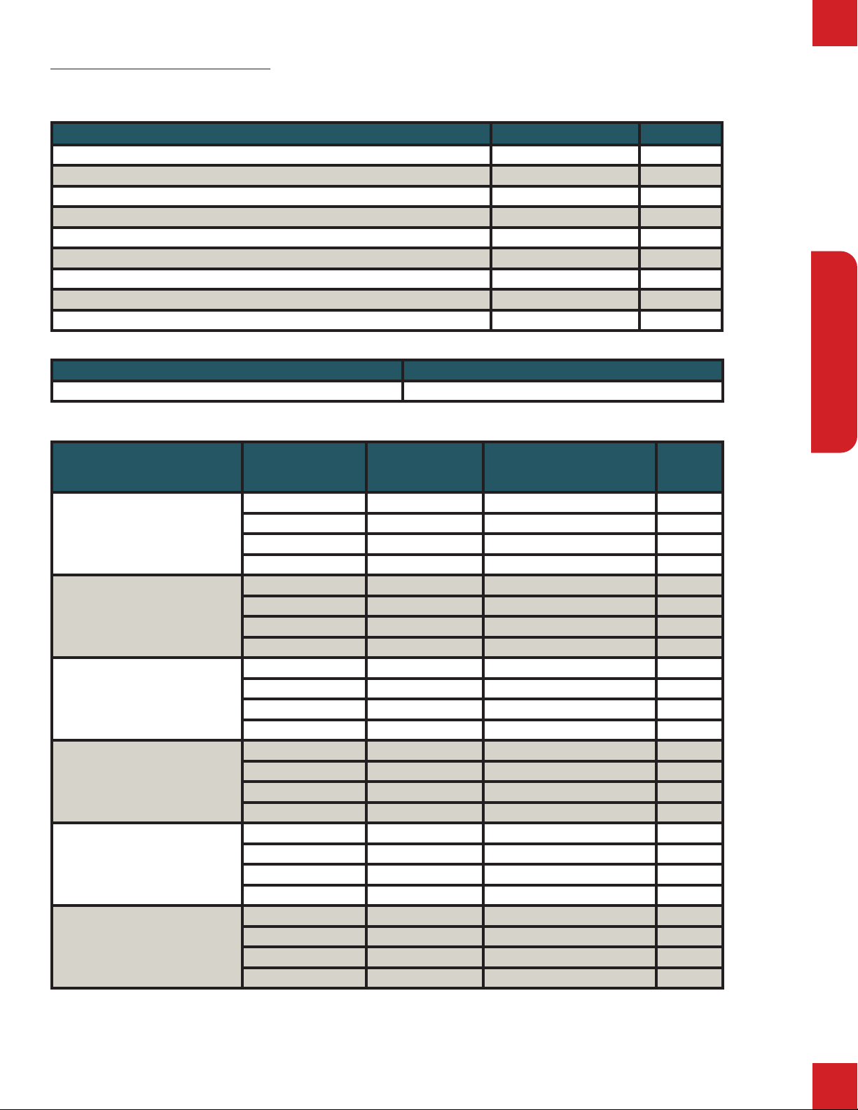
Export, Gas Conguration Data
Desnaon Country (Export)Supply Pressure (mbar) Category
AT-CH-CY-CZ-DK-EE-ES-FI-FR-GB-GR-HR-HU-IE-IT-LT-LU-LV-NO-PT-RO-SE-SI-SK-TR 20 2H
DE-PL-RO 20 2E
RO-NL 25 2L
BE-FR 20; 25 2E+
BE-CY-ES-FR-GB-GR-HU-IE-PT 30; 28-30 3B
DE-FI-NL-RO 30 3P
BE-CH-CZ-ES-FR-GB-GR-IE-IT-LT-NL-PL-PT-SI-SK 37 3P
AT-BE-CH-CY-CZ-DE-DK-EE-FI-GB-GR-HU-IT-LT-NL-NO-PL-RO-SE-SI-SK-TR 30 3B/P
BE-CH-CY-CZ-ES-FR-GB-GR-IE-IT-LT-PT-SI-SK-TR 28; 30/37 3+
Model “B”: BASO BGF378 valve
Electrical Supply Breaker / Circuit Required (per oven)
230VAC / 50Hz / 1Ph / 700W 16A
Model
Heang Category Orice
Manifold
High-Fire / Low-Fire
Shutter
(Air)
Opening
EDGE-1830
Gross Net kW/Hr
19.05 17.0
I2H / I2E 0.1405 in. 11.2 mbar #2
I2L / I2E+ 0.089 in. 17.4 mbar #2
I3P / I3+ 0.089 in. 24.9 mbar #3
I3B / I3B/P 0.089 in. 18.7 mbar #3
EDGE-2440
Gross Net kW/Hr
23.45 21.5
I2H / I2E 0.154 in. 11.2 mbar #2
I2L / I2E+ 0.1015 in. 17.4 mbar #2
I3P / I3+ 0.1015 in. 24.9 mbar #3
I3B / I3B/P 0.1015 in. 18.7 mbar #3
EDGE-3240
Gross Net kW/Hr
36.63 33.6
I2H / I2E 0.191 in. 11.2 mbar #2
I2L / I2E+ 0.120 in. 17.4 mbar #2
I3P / I3+ 0.120 in. 24.9 mbar #3
I3B / I3B/P 0.120 in. 18.7 mbar #3
EDGE-2460
EDGE-3260
Gross Net kW/Hr
43.96 40.3
I2H / I2E 0.209 in. 11.2 mbar #2
I2L / I2E+ 0.136 in. 17.4 mbar #2
I3P / I3+ 0.136 in. 24.9 mbar #3
I3B / I3B/P 0.136 in. 18.7 mbar #3
EDGE-3860
Gross Net kW/Hr
43.96 40.3
I2H / I2E 0.209 in. 11.2 mbar #2
I2L / I2E+ 0.136 in. 17.4 mbar #2
I3P / I3+ 0.136 in. 24.9 mbar #3
I3B / I3B/P 0.136 in. 18.7 mbar #3
EDGE-4460
EDGE-3270
EDGE-3870
Gross Net kW/Hr
54.22 48.4
I2H / I2E 0.2323 in. 11.2 mbar #3
I2L / I2E+ 0.154 in. 17.4 mbar #3
I3B / I3B/P 0.154 in. 24.9 mbar #3
I3B / I3B/P 0.154 in. 18.7 mbar #3

EDGE Original Installation, Operation and Service Manual
2
SPECIFICATIONS
SPECIFICATIONS
North America, Gas Conguration Data
Model
Heang Gas Type Supply Pressure Orice
Manifold
High-Fire / Low-Fire
Shuer (Air)
Opening
EDGE-1830
65k Btu/Hr
Natural 6”w.c. ~ 8”w.c. 0.1405 in. 4.5 inW.C. 1
Natural 6”w.c. ~ 8”w.c. 0.1405 in. 4.5 inW.C. #2
Propane 11”w.c. ~ 13”w.c. 0.0935 in. 10 inW.C. 1
Propane 11”w.c. ~ 13”w.c. 0.0935 in. 10 inW.C. #3
EDGE-2440
80k Btu/Hr
Natural 6”w.c. ~ 8”w.c. 0.154 in. 4.5 inW.C. 1.5
Natural 6”w.c. ~ 8”w.c. 0.154 in. 4.5 inW.C. #2
Propane 11”w.c. ~ 13”w.c. 0.1015 in. 10 inW.C. 1
Propane 11”w.c. ~ 13”w.c. 0.1015 in. 10 inW.C. #3
EDGE-3240
125k Btu/Hr
Natural 6”w.c. ~ 8”w.c. 0.191 in. 4.5 inW.C. 1.5
Natural 6”w.c. ~ 8”w.c. 0.191 in. 4.5 inW.C. #2
Propane 11”w.c. ~ 13”w.c. 0.120 in. 10 inW.C. 1
Propane 11”w.c. ~ 13”w.c. 0.120 in. 10 inW.C. #3
EDGE-3860
150k Btu/Hr
Natural 6”w.c. ~ 8”w.c. 0.209 in. 4.5 inW.C. 1.5
Natural 6”w.c. ~ 8”w.c. 0.209 in. 4.5 inW.C. #2
Propane 11”w.c. ~ 13”w.c. 0.136 in. 10 inW.C. 1
Propane 11”w.c. ~ 13”w.c. 0.136 in. 10 inW.C. #3
EDGE-2460
EDGE-3260
150k Btu/Hr
Natural 6”w.c. ~ 8”w.c. 0.209 in. 4.5 inW.C. 1.5
Natural 6”w.c. ~ 8”w.c. 0.209 in. 4.5 inW.C. #2
Propane 11”w.c. ~ 13”w.c. 0.136 in. 10 inW.C. 1
Propane 11”w.c. ~ 13”w.c. 0.136 in. 10 inW.C. #3
EDGE-4460
EDGE-3270
EDGE-3870
185k Btu/Hr
Natural 6”w.c. ~ 8”w.c. 0.2323 in. 4.5 inW.C. 1.5
Natural 6”w.c. ~ 8”w.c. 0.2323 in. 4.5 inW.C. #2
Propane 11”w.c. ~ 13”w.c. 0.154 in. 10 inW.C. 2
Propane 11”w.c. ~ 13”w.c. 0.154 in. 10 inW.C. #3
Electrical Supply Breaker / Circuit Required (per oven)
120VAC / 60Hz / 1Ph / 5.5A ~ 9.5A 20A (If GFCI protecon is required, use only panel breakers)

EDGE Original Installation, Operation and Service Manual 3
SPECIFICATIONS
SPECIFICATIONS
Dimensions
When installed as: Measurements are in inch unless otherwise noted
Detail Sin-
gle
Dou-
ble Triple EDGE
1830
EDGE
2440
EDGE
3240
EDGE
2460
EDGE
3260
EDGE
3860
EDGE
4460
EDGE
3270
EDGE
3870
A Chamber (W) 19.8 25.5 33.5 25.5 33.5 39.5 45.5 33.5 39.5
*Chamber (L) 30.3 40.0 58.5 68.5
*Chamber w/plugs (L) 31.3 41.0 59.5 69.5
B Window (D) 3.9
C Conveyor (L) 65.5 75.3 93.8 93.8 103.8
D Oven (D) 44.1 50.6 58.6 50.6 58.6 64.1 70.1 58.6 64.1
G Window (L) 20.0 35.0
H Cont. Cab. (L) 17.8
J Chamber (H) 3.5
K Motor (D) 5.3 3.8
Weight per packaged
oven
342 lbs ~
538 lbs
614 lbs ~
810 lbs
718 lbs ~
914 lbs
776 lbs ~
972 lbs
869 lbs ~
1000 lbs
899 lbs ~
1097 lbs
948 lbs ~
1170 lbs
978 lbs ~
1198 lbs
1070 lbs ~
1290 lbs
E Floor-Oven (H) 44.0 64.1 68.5
F Floor-Conveyor (H) t56.3
m52.0 36.0
b31.5 15.5
L Leg/Caster (H) 21.5 5.8
EDGE Original Installation, Operation and Service Manual
4
INSTALLATION
INSTALLATION
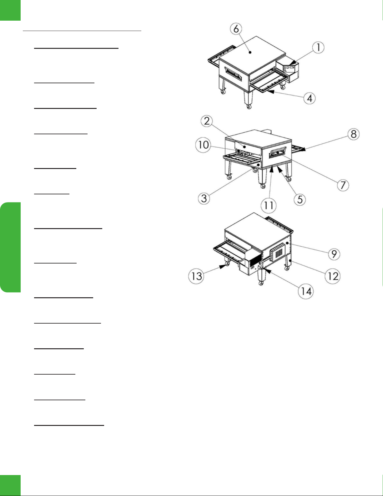
OVEN COMPONENTS
1. Control Can Assembly: Houses the operat-
ing controls for the oven and the natural gas
control devices and burner.
2. End Plug, Upper: Closes o the top half of the
bake chamber, above the conveyor belt.
3. End Plug, Lower: Closes o the bottom half
of the bake chamber, below the conveyor belt.
4. Conveyor Belt: Runs horizontally through the
bake chamber; carrying the product through
the oven.
5. Oven Base: Supports and insulates the bot-
tom of the oven.
6. Oven Lid: Mounts to the top of the oven, n-
ishes o the oven stack and covers the oven
insulation.
7. Half-Bake Window: Opens to allow the prod-
uct to be placed halfway through oven (half
bake time).
8. Crumb Pan: Located under both the entrance
and exit of the conveyor belt, catches debris
that falls through the conveyor belt.
9. Back Assembly: Closes o the back of the
bake chamber.
10. Plenum Assembly: Houses the hot air blower motor and fan, and thermocouples to monitor hot air
temperature.
11. Oven Bottom: Mounts to the top of the oven base, seals o the stack and covers the oven insula-
tion.
12. Oven Legs: Used with single- and double-stack congurations to raise / lower oven to convenient
working heights.
13. Oven Casters: Used on all oven congurations to allow moving the oven for installation and ser-
vicing.
14. Restraining Device: Secures the oven base to the wall to avoid damage to gas and electrical con-
nections.

EDGE Original Installation, Operation and Service Manual 5
INSTALLATION
INSTALLATION
INSTALLATION INSTRUCTIONS
IMPORTANT REQUIREMENTS
Oven installation must comply with local codes or, if local codes do not exist, with the National
Fuel Gas Code, ANSI Z223.1/NFPA 54 -OR- Natural Gas Installation Code, CAN/CGA-B149.1, or
the Propane Gas Installation Code, CAN/CSA-B149-2, as applicable.
This appliance must be electrically grounded in accordance with local codes, or if local codes
do not exist, with the National Electrical Code, ANSI/NFPA 70. OR with the Canadian Electrical
Code, CSA C22.2.
When this appliance is installed with casters, it must be installed with the casters supplied, a
connector complying with ANSI Z21.69 / CAN/CGA-6.16, a quick-disconnect device complying
with ANSI Z21.41, and a mechanism to limit movement of the appliance without straining the
connector or its associated piping system. This quick-disconnect device must not exceed 1.5
meters in length.
The gas supply tubing or hose shall comply with the national requirements in force and shall be
periodically examined and replaced as necessary.
This appliance and its individual manual shuto valves must be disconnected from the gas
supply piping system during any pressure testing of gas supply piping at pressures exceeding
1/2 psi (3.5 kPa).
The installer of this oven must contact local building and re ocials concerning inspections
and installation requirements of this oven and its ventilation system.
Unless otherwise stated, parts protected by the manufacturer or the authorized agent shall not
be adjusted by the installer.
In the event this appliance is to be converted to a gas type other than which it was originally ad-
justed for, contact manufacturer or authorized agent for the appropriate conversion kit (correct
orice & valve, correct appliance decal, and instructions)
Foreword
Gas must be present at the installation site at the time of the planned installation. If this is not possi-
ble, arrangements must be made with the installer or a comparable service provider to complete the
requirements of the Installation Checklist and First Firing inspection. This may incur additional cost to
you.
The utility connections to the oven MUST match the specications detailed for the oven(s) installation.
Ovens which are not installed on casters and ovens which are not plumbed using a exible gas hose
are immobile. These conditions will violate the terms of your warranty.
Extraction systems must meet the minimum requirements specied in this manual AND local code. The
oven control system must not be subjected to high heat. If the operating space is uncomfort-
able to work in, the extraction is insufcient for the oven. Heat will deteriorate control and
drive components, resulting in premature failure. Great care has been taken to equip your EDGE oven
with the highest quality of components and thermal protection abilities.
A preventative maintenance guide is provided in this manual. Please utilize it to keep your new oven(s)
operating at the best level.
EDGE Original Installation, Operation and Service Manual
6
INSTALLATION
INSTALLATION
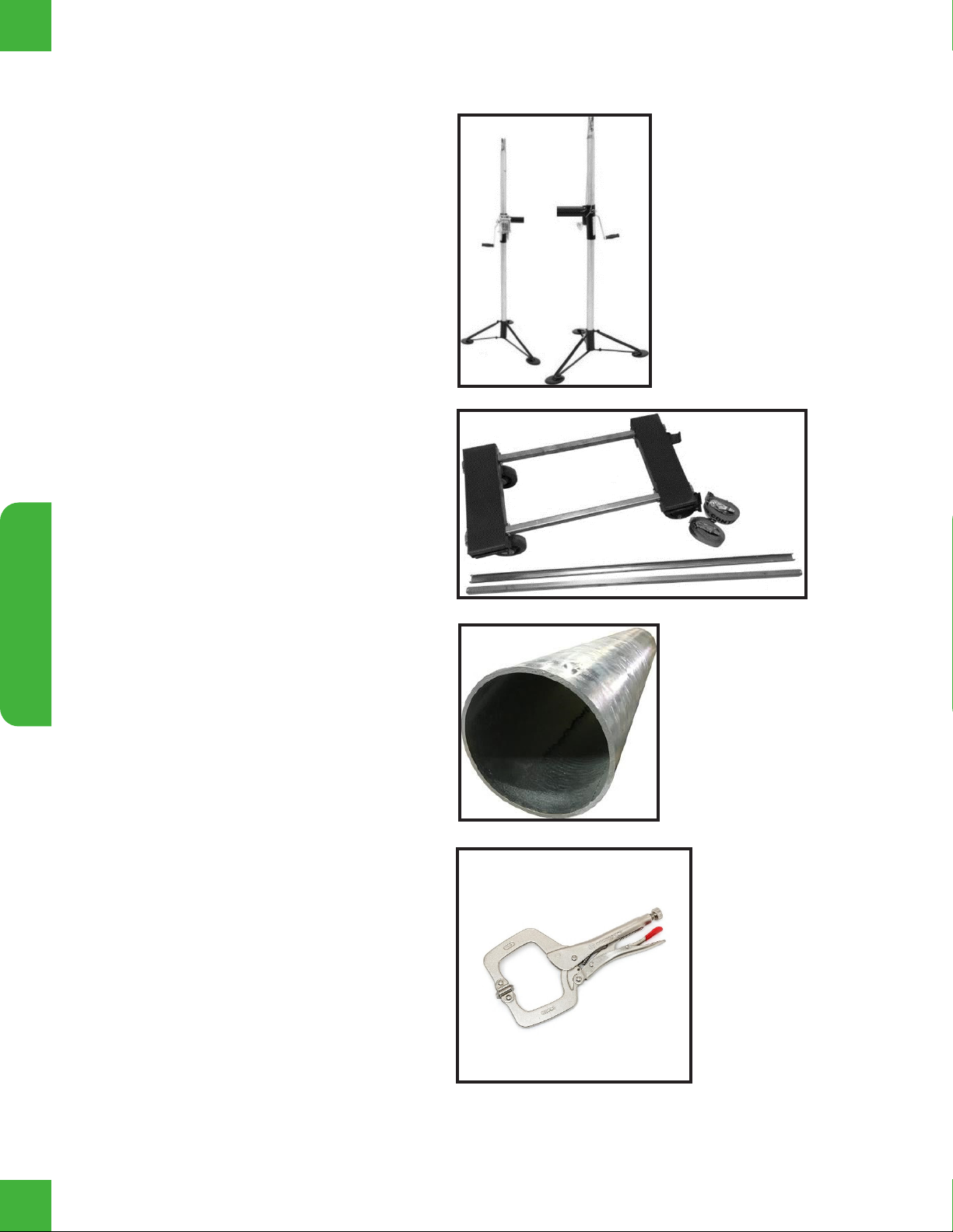
Tools & Equipment Required
LIFTING SYSTEM
(2) EDGE Lifting Jacks, PN: IE-9001,
Genie Lift or similar lifting system
(1) EDGE installation cart, PN: IE-9201,
4-wheel cart, pallet jack, or similar.
(1) 10ft, SCH40 steel pipe, 3” O.D. or
2.5” I.D. (Sourced locally)
(2) Clamps or locking pliers, when not
using EDGE Lifting Jacks IE-9001.
EDGE Original Installation, Operation and Service Manual 7
INSTALLATION
INSTALLATION
HAND TOOLS
(1) #2 Phillips Screwdriver
(1) Ratchet and short extension
(1) 5/16” Socket or nut driver
(1) 7/16” wrench
(1) 9/16” Socket
(1) 3/8” Socket or wrench *oven back
(1) Tin snips for cutting banding
(1) Adjustable wrench (Crescent) *as needed
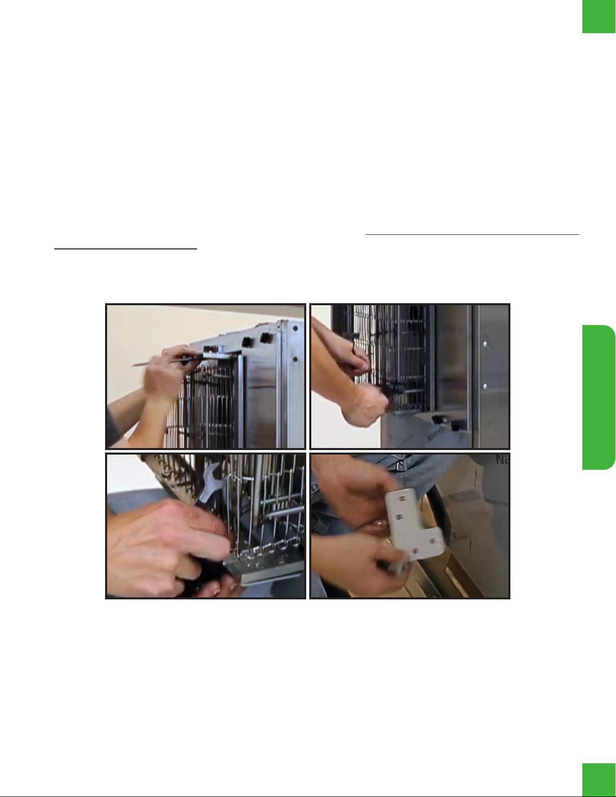
Stacking Ovens
1. Unpackage BOTTOM oven, retaining all attached documents and DO NOT cut any banding at this
point, the oven must remain attached to the cart or pallet. Inspect the oven for concealed shipping
damage before continuing.
2. Use dolly or cart to move the oven to the installation location, allow enough room for the oven to be
lifted, rotated, and stacked.
3. Remove the “L” brackets from the belt frame. Retain the hardware, as it is needed for reassembly.
EDGE Original Installation, Operation and Service Manual
8
INSTALLATION
INSTALLATION
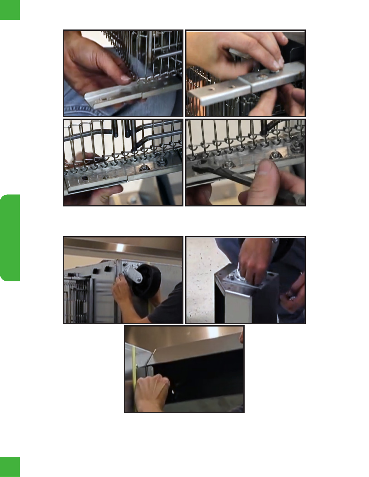
4. Install the supplied belt frame hinge using the previously removed hardware.
5. For Triple Stacked ovens, the casters are to be fastened directly to the bottom oven base. Single
and Double Stacked ovens, the casters are to be attached to the supplied legs, which will then be
attached to the bottom oven base.

EDGE Original Installation, Operation and Service Manual 9
INSTALLATION
INSTALLATION
6. Remove the fasteners from the pallet shipping bracket.
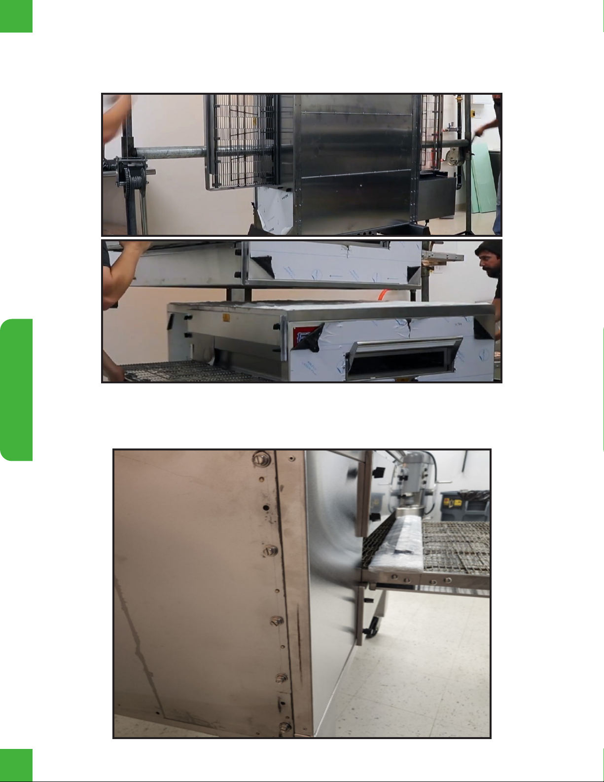
7. With the belt now straight and assembled and the oven released from the pallet, pass the 3” O.D.
Schedule 80 pipe through the lifting plates and the oven body.
8. Using your Genie Lifts and at least 2 people, begin lifting the oven, rotating it until you clear the oor
surface. Banding straps may be removed once the oven is lowered to the ground.
EDGE Original Installation, Operation and Service Manual
10
INSTALLATION
INSTALLATION
9. Stacking ovens in a Double or Triple Stack requires enough room for the base oven to be moved
clear of your work area. Simply repeat the process for each additional oven, continuing the lift until
each additional oven clears the height of the oven stack.
10. With a helper maintaining control of the suspended oven, remove the 2 fasteners from each of the
pallet shipping brackets. DO NOT DISCARD THE FASTENERS. Once each bracket is removed,
install the fasteners back into the screw holes of the oven they were removed from. There should be
5 fasteners in each side of the oven back.
This manual suits for next models
10
Table of contents


