ERC FAILURE CODES
The oven may stop operating but not give an F code on the display immediately.
F codes are stored in nonvolatile eeprom memory until the same fault occurs twice
consecutively. After that, the F code will be displayed. F codes can be recalled by press-
ing together 3, 1 and 0. While F codes are displayed, pressing 8and 6together will
clear them. A fault must exist continuously for 5 minutes before an F code is recorded
(F2 and F8 are 1 minute or sooner). Press Cancel/ Off to exit failure code mode.
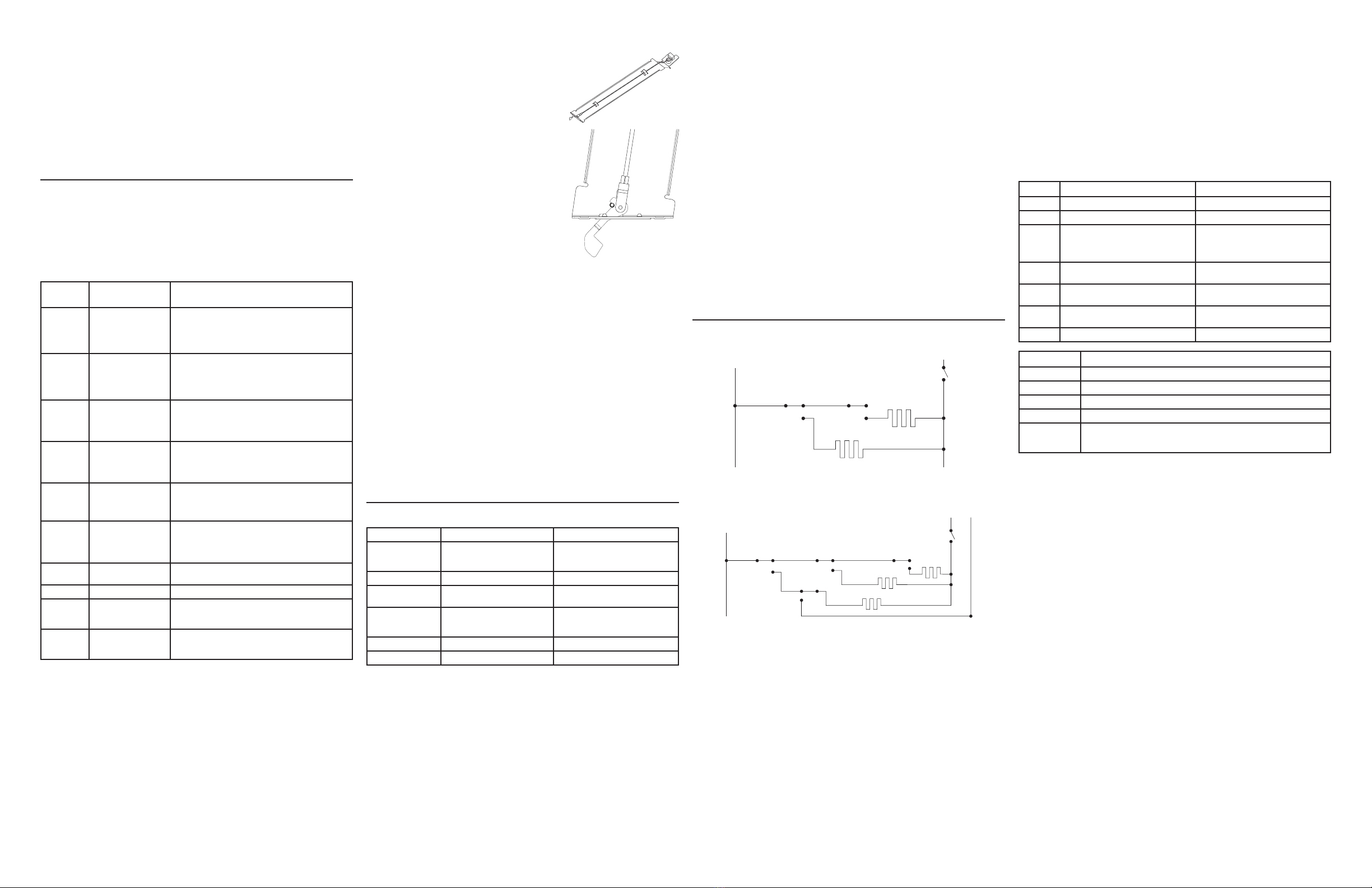
MOTORIZED DOOR LOCK
The motorized door lock assembly is located above the
oven. The assembly consists of
a lock motor cam and switch assembly,
lock hook, mounting plate and heat barrier.
Motorized Door Lock Operation
The lock motor is energized when the control
is set for the Clean and Clean Time is selected. The K12
(upper) or K905 (lower) relay contact will close and com-
plete the circuit that supplies
the voltage to the lock motor.
NOTE: To enable proper operation of the door lock, ensure that the door jamb switch
is closed.
NOTE: Display of Control will flash “LOCK” if the door switch is in the open position
(door open).
• The words “LOCK” will flash on and off in the display while the lock motor is in
motion. When the door is locked, the word “LOCK” remain illuminated in the display.
• CAM – The cam on the motor performs two functions:
1. Positions the lock hook in the door to prevent opening during clean operation.
2. Operates the lock switches which tell the control if the door is unlocked or locked
and ready for clean operation.
NOTE: The door lock switch will be open when the latch is locking. Once locked, the
door switch will be closed.
SPECIAL FUNCTIONS
The control has a section that can be entered to change how the control will work.
To enter this section, press and hold the Bake and Broil pads for 3 (three) seconds
and “UP OFFSEt” appears in the display. Scroll through options using the 3(up) and 8
(down) number pads. Select and confirm options using the 0number pad; cancel with
the 6number pad.
• Sabbath Mode – “SAbbAth” - Enables or disables Sabbath Mode.
• Clock Display – “Cloc diSP” - Turns clock on or off.
• Clock Configuration– “Cloc cFg” - Configures clock to 12- or 24-hour time.
• Auto Recipe – “Auto rEciPE” - Turns auto convection conversion on or off.
• Degree Unit – “dEg Unit” - Configures temperature to Celsius or Fahrenheit.
• 12-hour Shutoff – “12H ShutoFF” - Enables or disables 12-hour shutoff.
• End Tone – “End tonE” - Sets end tone to single or continuous beep.
• Sound – “Sound” - Adjusts volume level to low “Lo”, medium “Reg”, or high “Hi”.
• Lower Oven Offset – “Lo OFFSEt” - Adjusts temperature up or down by up to 35º F
for lower oven.
• Upper Oven Offset – “UP OFFSEt” - Adjusts temperature up or down by up to 35º F
for upper oven.
The controls may be locked out by pressing the Lock Control pad for 3 seconds;
display will show “Loc On”. It may be unlocked by pressing the Lock Control pad for 3
seconds again; display will show “Loc Off”.
• If a button is pressed while the control is locked, “Loc On” will show in the display.
• The Cancel/Off pad will always work, regardless of whether the control is locked.
Failure
Code
Meaning Correction
F2.0, F2.1 Upper Oven temperature
inside oven cavity as
measured by sensor
over 650°F unlatched or
915°F latched.
a) Welded relay contacts
b) Airflow to rear of unit
c) High resistance in oven sensor leads/ connectors
(especially at sensor in rear)
F2.2, F2.3 Lower Oven temperature
inside oven cavity as
measured by sensor
over 650°F unlatched or
915°F latched.
a) Welded relay contacts
b) Airflow to rear of unit c) High resistance in oven sensor
leads/ connectors (especially at sensor in rear)
F3.0 Shorted Upper oven
sensor (under 950 ohms)
a) Disconnect power. Disconnect sensor harness from
control. Measure sensor resistance (white leads) to be -1080
ohms at room temperature with 2 ohms per degree change.
b) Separate sensor from harness to determine fault.
F3.1 Open Upper oven sensor
(over 2900 ohms)
a) Disconnect power. Disconnect sensor harness from
control. Measure sensor resistance (white leads) to be -1080
ohms at room temperature with 2 ohms per degree change.
b) Look for damaged harness terminals if not a bad sensor.
F3.2 Shorted Lower oven
sensor (under 950 ohms)
a) Disconnect power. Disconnect sensor harness from
control. Measure sensor resistance (white leads) to be -1080
ohms at room temperature with 2 ohms per degree change.
b) Separate sensor from harness to determine fault.
F3.3 Open Lower oven sensor
(over 2900 ohms)
a) Disconnect power. Disconnect sensor harness from
control. Measure sensor resistance (white leads) to be -1080
ohms at room temperature with 2 ohms per degree change.
b) Look for damaged harness terminals if not a bad sensor.
F7.0, F7.2,
F7.3
Shorted key matrix. OFF
key or Stuck Key
Replace control.
F8.0, F8.1 EEPROM data shift failure If repeated, replace control.
F9.0, F9.1,
F9.4
Upper door latch
changed state
unexpectedly
Check upper door latch assembly & welded relay
F9.2, F9.3,
F9.5
Lower door latch
changed state
unexpectedly
Check lower door latch assembly & welded relay
SH. 2 of 4 31-17195-2
CONVECTION FAN
Symptom Possibility Correction
No fan operation Open winding as indicated by ohm
check red to grey and blue to grey
(approx. 60 ohms each)
Replace motor.
Fan loud Loose shaft nut Tighten shaft nut. Do not bend blade.
Fan loud Convect cover screws or cavity
screws loose
Tighten. Use larger screw if stripped.
No fan operation Check voltage CCW to N – should
read 120VAC in Convection Bake.
• If no voltages, replace ERC.
• If voltages OK, check harness or
winding resistance.
No fan operation Shaft or blade rubbing on oven liner Loosen screws/readjust position/tighten.
No fan operation Jamb switch NO to C is open Replace jamb switch or check harness.
NOTES:
• QUARTER TOP HEAT – There is an additional relay which connects the L1 side of Broil
to neutral instead of L1, therefore applying 120V to the broil element during select
modes or portions of modes. Quarter top heat is on with the bake element during the
following cycles: Bake preheat & steady state, Convection bake preheat and steady
state, Convection roast preheat and steady state and Self Clean stage 2.
• BAKE/TIME BAKE – The bake, broil and convection elements cycle during preheat
with one element on at a time. The convection fan also operates while preheating
and will turn off once the set temperature is reached. Once the bake preheat
temperature is reached, the bake and broil elements cycle for the balance of the
bake operation with one element on at a time.
• CLEAN – The broil element is on only during the first 30 minutes or until the sensor
reaches 750°F. During the balance of the clean cycle, the oven will cycle between
the bake and broil units.
• STEAM CLEAN – Bake unit turns on continuously for 3 minutes at the start of the
cycle. The bake element turn off after 3 minutes and no additional heat is generated
for the balance of the cycle.
• See schematic for wattage values
L1
ACK
K908
BROIL
BROIL
BAKE
K907
QTH
K909
BAKE
K910
CONV
CONV
RED
DLB
K915
L1
ACK
RED
K7
DLB
K3
UPPER BROIL
K18
UPPER BAKE UPPER BAKE
UPPER BROIL
KEY PANEL TEST
1. Touch each pad on the Key Panel.
2. If the Key Panel is functioning properly, the following should occur:
• Bake, Broil, Convection Bake, Convection Roast, Warm Self Clean, and Timer
Modes – An audible tone sounds and the display shows the mode of the operation
selected.
• Cancel/Off, Cook Time and Delay Time – An audible tone sounds and the display
shows the time of day.
• Number pads can only be used after another function has been selected.
• Oven Light - Oven light turns on. Audible tone. Relay click.
Troubleshooting Door Lock
If the door will not lock, check that the door jamb switches work. If lights are good,
then when the doors are both closed the lights should turn off. If lock icon flashes,
indicating the oven is trying to lock the door, check for voltage at the lock motor
(on the rear of the cavity). If 120V is present, turn off power, disconnect harness and
check the lock motor for resistance using ohmmeter. Lock motor should be around
3400Ω. If not, replace lock motor.
Upper Oven
Lower Oven
SERVICE MODE
Power must be cycled within 2 hours before user can enter Service Mode. To enter
Service Mode press and hold the 1 & 5 pads for 2 seconds. Entering into service mode
will turn off all other active modes. When the Service Mode is entered, the word “tESt”
will appear in the time display. If a key is pressed while another load is already on, the
control will turn off the first load and then activate the new load. Note that for the Self
Clean and Self/Steam Clean keys, the control will ignore additional Self and Self/Steam
Clean key presses and not keep track of state for every time the corresponding key is
pressed. The Door Lock will only seek the opposite state when the key is pressed while
in a known state. DLB will always be energized while in Service Mode. All keys will play
the “Touch” tune upon press. Each key press will turn on the associated load. Each
load will turn off when one of the following conditions is met: the same key is pressed
again; another key has been pressed; or 15 seconds has passed after the key has
been released. The loads and associated keys for the control are listed below:
Key Action - Upper Action - Lower
Bake Energize Bake; “Bake” illuminated Energize Bake; “Bake” illuminated
Broil Energize Broil; “Broil” illuminated Energize Broil; “Broil” illuminated
Self Clean Cycle Door Locks positions; “Door” and Lock
icons flash (1/2 second ON 1/2 second OFF)
during transition, ON solid when locked, OFF
when unlocked
Cycle Door Locks positions; “Door” and Lock
icons flash (1/2 second ON 1/2 second OFF)
during transition, ON solid when locked, OFF
when unlocked
Convection
Bake
No Action Energize Convection Bake, Convection Fan
Enable; “Conv” and “Bake” illuminated
Cook Time Read and show Upper oven sensor value
(in degrees F)
Read and show Lower oven sensor value
(in degrees F)
Warm No Action Energize Broil; “Warm” (rightmost Warm
icon) illuminated
Cancel/Off Reset the control Reset the control
Key Action
1
Energize Convection Fan (turn fan)
3Display control Application version
4Display control Parametric version
Oven Light Energize Oven Light relay(s)
Timer On/Off Light up all LED segments. It is normal for some LED segments to turn off after some
time. For example, if the door is unlocked,
the lock LEDs will not stay on the full 10 seconds


