MFJ VersaTuner III User manual


MFJ-962E Instruction Manual
2
Introduction
The MFJ-962E is a "T" network roller inductor tuner with built-in antenna switching, RF power
and SWR metering, and a 1:1 balun. The largest amplifiers that can safely be used include the
Heathkit SB-200 and 201, Collins 30L1, and Ameritron's ALS-600, ALS-606, and AL-811 series
of amplifiers. This tuner is designed for maximum RF output power levels of 800 watts carrier
or PEP on 80-10 meters, and 500 watts carrier or PEP on 160 meters. It is designed to match 50
ohm output amplifiers, transmitters or transceivers to virtually any antenna. Peak and average
forward power, reflected power, and SWR are displayed on the wattmeter's illuminated cross-
needle meter.
The MFJ-962E uses a roller inductor "T" matching network. It continuously tunes all
frequencies from 1.8 through 30 MHz. It will match dipoles, inverted-vee's, verticals, mobile
whips, beams, random wires, and many other antennas. The built-in balun will work with
balanced open wire, twinlead, or twin-axial feedlines.
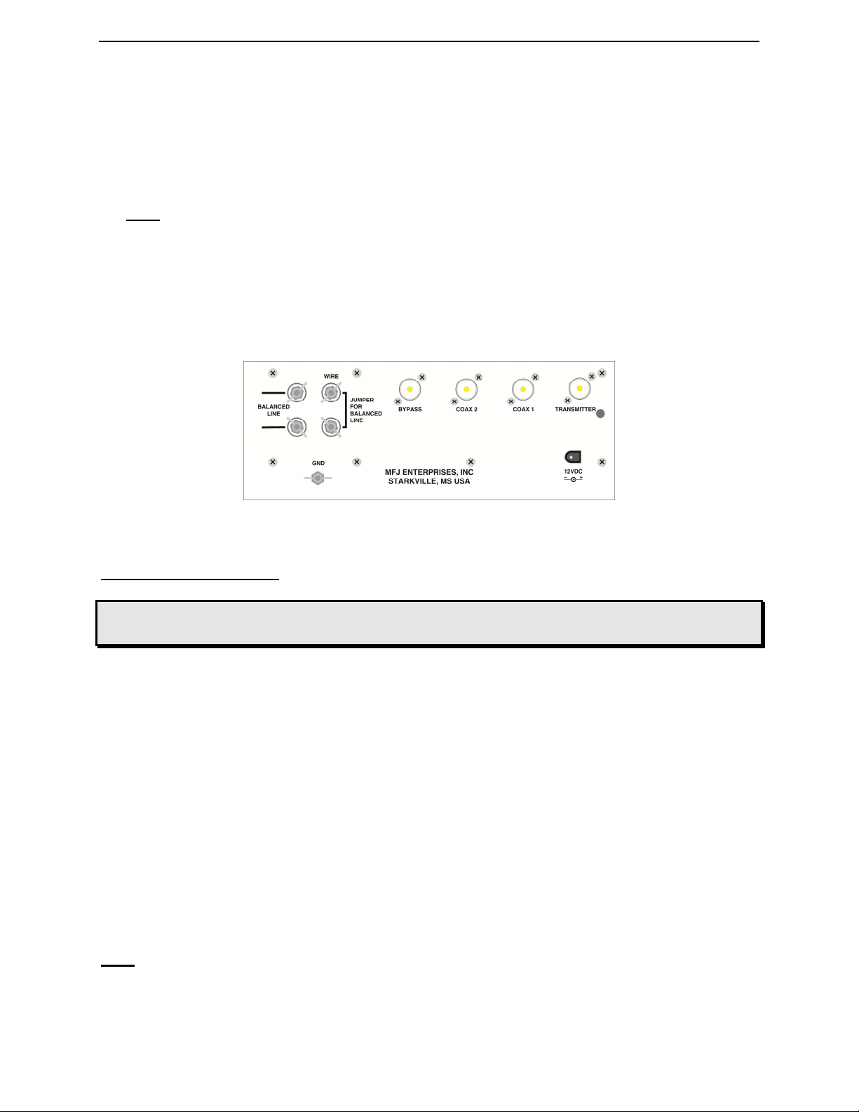
An internal six position antenna-selector switch selects two separate coaxial line outputs, either
in tuned (with tuner's matching network in line) or direct (no matching circuit) configurations, a
balanced line or wire output, and a coax bypass position for accessories such as an external
dummy load. Long wire antennas can be connected to the WIRE terminal in the BAL.LINE
setting.
The antenna switching board uses nine 16A 1KV relays to switch the antennas. Note the tuner
requires 12V to operate which can come from the station power supply or one of the MFJ power
adapters.
Understanding Power Ratings
There are no standardized power rating systems for tuners. The names used (i.e. 3 kW Tuner)
carry over from the time when amplifiers were rated by peak power input, and not the true RF
power output. For example, the one thousand watt Johnson Matchbox was rated to handle a
1000 watt plate modulated AM transmitter (four kilowatts PEP transmitter input and 3000 watts
PEP RF output). The Heathkit SB-220 was called a two kilowatt amplifier, and the rated output
for SSB is approximately 1200 watts PEP and CW approximately 600 watts. Matching tuners
were called 2 kilowatt tuners, and these tuners safely handled 600 watts of CW power and 1200
watts PEP SSB.
The FCC has changed the power rating system of amplifiers a while back, and tuners no longer
follow amplifier power ratings. Most typical 1500 watt tuners remain able to safely handle 400-
600 watts CW, and 600-900 watts PEP SSB.
Load conditions and control settings also greatly affect the power handling capability of the
tuner. T-networks typically handle more power on higher frequency bands into higher load
impedances. The worst operating condition for T-network tuners are low impedance capacitive

MFJ-962E Instruction Manual
3
reactance loads. T-network tuners always handle the least power when operated on 160 meters
into low impedance capacitive reactive loads.
Front Layout
Figure 1
Peak Reading SWR/Wattmeter
The cross-needle meter measures the peak or average FORWARD power, REFLECTED
power, and SWR. The illuminated cross-needle meter operates with the antenna tuning circuit in
or out of line. The wattmeter can be used without the tuning network by setting the ANTENNA
SELECTOR to either of the two COAX DIRECT positions of the antenna selector or the
BYPASS position. The wattmeter is active in all positions of the ANTENNA SELECTOR.
The meter's full scale forward and reflected power range is controlled by the left POWER switch
that selects 3000W (HI) or 300W (LO). If your transmitter runs more than 300 watts of output
power, set this switch to the 3000W HI (in) position. If your transmitter has less than 300 watts
of output, set this switch to the 300W LO switch position (out).
Peak envelope power (PEP) is measured when the PEAK or AVG POWER push button (right-
hand side) in placed in the PEAK (in) position. Peak power and average power values are equal
with steady unmodulated carriers, FSK, or FM. The meter reading on these modes will be the
same whether the PEAK / AVG button is pressed or released. On SSB, the PEP meter reading
should be twice the average power with two tone test modulation.
On SSB, the ratio of PEP to average power varies with different voice characteristics. With most
voices, the PEP reading is three to five times higher than the average voice power reading. The
most accurate peak envelope power readings are obtained only with sustained carrier, voice or
two tone test modulation.
Forward power is displayed on the left-hand FORWARD meter scale. This scale is calibrated
from 0 to 300 watts and is read directly in the 300 watt position. Each picket (scale mark)
represents 5 watts below 10 watts, 10 watts between 10 and 100 watts, 25 watts above 100 to
200 watts, and 50 watts above 200 watts. In the 3000W (HI) position the forward power scale
must be multiplied by 10. Each picket represents 100 watts below 1000 watts and 250 watts
from 1000 to 2000 watts, and 500 watts above 2000 watts.

MFJ-962E Instruction Manual
4
The reflected power is read on the right-hand REFLECTED meter scale. This scale indicates 60
watts full scale when the 300W power sensitivity is selected, and 600 watts full scale when the
3000W power scale is selected. This scale has a picket every watt below 10 watts and every 5
watts above 10 watts. This scale is also multiplied by 10 when using the 3000W power position.
The most accurate power readings occur in the upper half of the meter scales. When trying to
measure power with a less than perfect match, the reflected power should be subtracted from the
forward power readings.
The SWR is read directly from the nine red SWR curves that range from 1:1 to infinity. SWR is
measured by observing the point where the forward and reflected power needles cross. The SWR
is indicated by the red curve closest to the needle crossing point. No cumbersome or time
consuming SWR sensitivity adjustments are required with this meter.
The wattmeter has an internal lamp that backlights the meter scale. The METER LAMP ON /
OFF switch turns the meter lamp on and off. The antenna relay switching network and the peak
power circuit requires power from an external 12 VDC source, such as the optional MFJ-1312B
power supply. The rear panel jack accepts a 2.1 mm coaxial plug with the center conductor
positive (+) and the sleeve negative (-). The negative lead is grounded inside the tuner.
Antenna Selector
The ANTENNA SELECTOR allows you to select either of the 2 rear panel SO-239 antenna
coaxial connectors, direct or through the tuner, a coax bypass output, and balanced feedline or
wire antennas.
Installation
CAUTION: Locate the tuner so that the rear panel is not accessible during
operation.
1. Locate the tuner in a convenient location at the operating position. If balanced line or wire
line operation is used, the feed through insulators may have high RF voltages. These
voltages can cause serious RF burns if the terminals are touched when transmitting. Be sure
to locate the tuner so that these terminals can not be accidentally contacted during
operation.
2. Install the tuner between the transmitter and the antenna as shown in the diagram below. Use
a coaxial cable capable of handling the power (such as RG-8/U) to connect the transmitter (or
amplifier) and to the connector marked TRANSMITTER on the rear of the tuner.
3. Connect the antenna(s) to the tuner as follows:
The tuner or meters will not function without 12VDC.

MFJ-962E Instruction Manual
5
A. Coaxial feedlines connect to the coax connectors 1 and 2 coax line (fed direct or through
matching circuit as selected by the ANTENNA SELECTOR switch).
B. Random wire or single wire line antennas should be connected to the WIRE terminal.
Note: Route all single and random wire antennas to prevent RF burn hazard.
C. Any balanced feedline (open wire, twinlead, or twin-axial lines) is connected to the
BALANCED LINE terminals. Connect a jumper between the WIRE terminal and the
terminal below it to enable the balanced line terminals.
4. A ground post is provided for an RF ground connection.
Back Layout
Figure 2
Using The MFJ-962E
WARNING: Never change the Antenna Selector position while transmitting!
Never apply more than 800 Watts to the MFJ-962E !
In any conventional "T" network tuner, maximum power handling and the smoothest tuning
occurs when the capacitance in the network is as large as possible. In this tuner the
TRANSMITTER and ANTENNA MATCHING controls have maximum capacitance at
position 0(fully meshed), and minimum capacitance at position 10 (fully open). Be sure to use
the highest possible capacitance for each band. This will provide the smoothest tuning, highest
efficiency, and greatest power handling capability.
The roller inductor has a minimun inductance when the knob is rotated fully clockwise and the
counter displays approximately "125". When the roller is rotated fully counter-clockwise, it has
maximum inductance and the counter display is set at "000". If the counter is not set a "000"
when the roller is rotated fully counter-clockwise, reset the counter to "000". Reset the counter
by using a small screwdriver or a pencil and push the reset lever through the hole beside the
counter.
Note: If your transmitter uses an adjustable output circuit, it must be properly tuned into a 50
ohm load at the operating frequency. Proper tuning can be accomplished by placing the
ANTENNA SELECTOR switch in the fully clockwise COAX BYPASS position with a

MFJ-962E Instruction Manual
6
dummy load attached to the BYPASS coax connector. Adjust the transmitter according
to the manufacturer's instructions into the 50 ohm dummy load before adjusting the tuner.
Most modern solid state transceivers do not require adjustments. If the transceiver has a built in
antenna tuner, be sure it is turned off or disabled.
After properly preparing the transmitter, place the MFJ-962E ANTENNA SELECTOR switch
in the desired antenna position in the COAX 1 BYPASS or COAX 2 BYPASS setting. If the
SWR is low (very little or no reflected power), the tuner can be left in this position.
If the SWR is higher than desired, place the ANTENNA SELECTOR switch in the COAX 1 or
COAX 2 setting to select the desired antenna. Adjust the tuner as described below to obtain the
best SWR. Do NOT change the transmitter's tuning (plate) or loading (antenna) controls until
AFTER the tuner has been fully adjusted. The transmitter can be "touched up" (if necessary)
after the MFJ-962E is fully tuned to minimum SWR.
Operation
The roller inductor has maximum inductance at "000" and minimum inductance about "125" on
the reference counter. The capacitors have minimum capacitance at 0 and maximum capacitance
at 10. In simple language, as the frequency is increased, the normal control positions rotate
clockwise just like on other equipment.
Note: Always use the most capacitance (settings closest to 0) for the most power handling and
the least loss. Use the smallest possible inductance (the highest number possible) also.
Note: The MFJ Air Core™ Roller Inductor is designed with an exclusive Self-Resonance
Killer™ that keeps potentially damaging self-resonances away from your operating
frequency. This feature is switched in and out of the circuit with a built-in switch in the
roller. Therefore, as you turn the roller up and down, you may feel a bump about mid
range. This is normal and you should not be alarmed.
Increase the number the controls are set at (on a given frequency) to INCREASE the matching
range. Remember, this LOWERS the efficiency and power handling capability of the tuner.
1. Tune the exciter into a dummy load (most solid state transmitters are "pre-tuned" to 50 ohms
and do not require adjusting with the dummy load).
2. Select the desired antenna with the ANTENNA SELECTOR.
3. Position the ANTENNA and TRANSMITTER controls at the following settings:
160 M: 0 20 M: 4
80 M: 1 17 M: 6
75 M: 2 15 M: 7
40 M: 3 12 M: 8
30 M: 3-1/2 10 M: 8-1/2

MFJ-962E Instruction Manual
7
Then place the POWER switch in the LO and AVG meter positions.
4. Starting from the minimum INDUCTOR position (highest number), turn the INDUCTOR
control counter-clockwise (adding more inductance) while applying a slight amount of
power (less than 25 watts). Tune for the lowest reflected power and maximum forward
power (lowest SWR).
5. In this order, adjust the ANTENNA control, INDUCTOR, and TRANSMITTER control
for lowest reflected power (and SWR). Repeat this step a few times until the reflected
power is zero.
6. If the SWR did not reach 1:1 in step 5, turn the INDUCTOR control counter-clockwise (to
a lower number) again and repeat Step 5. For maximum power handling and efficiency,
always adjust the capacitors to the lowest front panel number (highest capacitance) that
allows proper antenna matching. This insures maximum power handling and lowest power
loss in the tuner.
7. Advance the power (do not exceed 100 watts) and, if necessary, touch up the ANTENNA
and TRANSMITTER controls for minimum reflected power and maximum forward power
(lowest SWR). Remove the power.
8. After adjusting the tuner for minimum SWR, the amplifier may be turned on. The METER
switch should be placed in the HI position, and the amplifier tuned according to the
manufacturer's instruction.
9. For quick retuning of the tuner, record the INDUCTOR and CAPACITOR settings for
each band.
Note: Maximum power handling occurs when both the TRANSMITTER and ANTENNA
capacitors are set at the lowest front panel numbers and the inductor is set at the
highest possible number that permit matching the antenna. Following this guideline
will insure maximum power handling capability and efficiency, and the least critical
tuning adjustments.
Operating Notes
1. While this tuner is designed to have as large a tuning range as possible, there are limits to the
tuning range of the capacitors. Some antennas may require more or less capacitance than the
controls have. In these cases, the SWR may not be reduced to 1:1. If the SWR is higher than
the limits on your rig, try changing the length of the antenna or feedline to bring the
impedance within the tuning range of the tuner.
2. When adjusting the tuner, use the lowest number on the TRANSMITTER, ANTENNA, and
minimum INDUCTANCE that produces a good SWR. This will reduce tuner losses and
increase the power rating of the tuner.

MFJ-962E Instruction Manual
8
WARNING:
1. Never operate the tuner with the top removed. Contact with the components
inside the tuner while transmitting will result in painful RF burns.
2. Never rotate the ANTENNA SELECTOR switch while transmitting. Doing so
may permanently damage the relays.
3. Locate the tuner so that the rear terminals ARE NOT accessible during
operation. The single wire and balanced line connections may have high
voltage while being used.
4. Disconnect all antennas from the tuner during lightning storms.
5. Always tune with low power (i.e. less than 100 watts). Apply maximum power
only after tuning up.
6. Be sure to adjust the SWR before transmitting at high power (above 100
watts). Do Not transmit with a high SWR for extended periods of time.
In Case Of Difficulty
If the tuner fails to tune, please double check all connections and follow the tuning procedures
again. Be sure you are using enough inductance (high enough inductance number) and have the
capacitors open far enough (higher front panel numbers).
If the tuner arcs at the rated power levels, please double check all connections and follow the
tuning procedures again. The power rating of this tuner is 900 watts PEP RF power. Be sure you
are using the least amount of inductance (lowest number) and the greatest capacitance (lowest
number) possible that still allows matching the load on the operating frequency.
Note: If this tuner arcs when operating on the 160 meter band, it may be necessary to reduce
transmitter output power.
If you are still unsuccessful, but the tuner does adjust and operate when switched to a dummy
load or another antenna, please read the Antenna System Hints section.
Grounding Hints
To minimize RFI, single wire feedlines (such as used with Windom or longwire antennas) should
be kept away from other wiring. Radiation will be minimized if the single wire feeder runs
parallel and reasonably close to the wire that connects the tuner to the outdoor ground. The
antenna feed wire should be adequately insulated to prevent arcing or accidental contact.
For safety, please use good dc and RF grounds. It is particularly important to have a good RF
ground while using a single wire feeder. When using a single wire feeder, the tuner needs
something to "push" against in order to force current into the single wire feedline. If a good RF

MFJ-962E Instruction Manual
9
ground is not available, RF will usually find it's way back into the power line (RFI), transmitter
audio circuits (RF feedback), or the operator (RF burns).
Water pipes and ground rods provide good dc and ac safety grounds, but they are often
inadequate for RF grounding because they are single conductors. Ground rods by themselves are
almost useless for dependable RF grounding.
RF grounds work much better when "spread out" over a large area, especially when they employ
multiple connections directly to the equipment ground point. Water pipes, heating ducts, and
fences may work (especially if they are connected together with multiple wires), but the best RF
grounds are radial systems or multi-wire counterpoises. Radials and counterpoises provide large,
low resistance surfaces for RF energy.
RF and lightning travels on the surface of conductors. Braided or woven conductors have high
surface resistance to lightning and RF. Ground leads for RF and lightning should have wide
smooth surfaces. Avoid the use of woven or braided conductors in RF and lightning grounds
unless the lead needs to be flexible.
CAUTION: For operator safety, a good outside earth ground or water pipe ground
should always be installed and connected to the case of the MFJ-
962E. Make certain the safety ground also connects to the transmitter
and other station accessories. A wing nut post marked GROUND is
provided for ground connection(s).
Antenna System Hints
For operator safety, a good outside earth ground or water pipe ground should always be installed
and connected to the case of the MFJ-962E. Make certain the safety ground also connects to the
transmitter and other station accessories. A wing nut post marked GROUND is provided for
ground connection(s).
Location
For the best performance, an end-fed longwire wire antenna should be at least one quarter-
wavelength long at the operating frequency. Horizontal dipole antennas should be at least a half-
wavelength long and located as high and clear as possible. While good RF grounds help the
signal in almost any transmitting installation, it is extremely important to have good RF grounds
with long wire or other Marconi style antennas.
Matching Problems
Most matching problems occur when the antenna system presents an extremely high impedance
to the tuner. When the antenna impedance is much lower than the feedline impedance, an odd
quarter-wavelength feedline converts the low antenna impedance to a very high impedance at the
tuner. A similar problem occurs if the antenna has an extremely high impedance and the
transmission line is a multiple of a half-wavelength. The half-wavelength line repeats the very
high antenna impedance at the tuner. Incorrect feedline and antenna lengths can make an
otherwise perfect antenna system very difficult or impossible to tune.

MFJ-962E Instruction Manual
10
One example where this problem occurs is on 80 meters when an odd quarter-wave (60 to 70
foot) open wire line is used to feed a half-wave (100 to 140 foot) dipole. The odd quarter-wave
line transforms the dipole's low impedance to over three thousand ohms at the tuner. This is
because the mismatched feedline is an odd multiple of 1/4 wavelength long. The line inverts (or
teeter-totters) the antenna impedance.
A problem also occurs on 40 meters with this same antenna example. The feedline is now a
multiple of a half-wave (60 to 70 foot) and connects to a full-wave high impedance antenna (100
to 140 foot). The half-wave line repeats the high antenna impedance at the tuner. The antenna
system looks like several thousand ohms at the tuner on 40 meters.This places enormous strain
on the balun and the insulation in the tuner, since voltages can reach several thousand volts. This
can cause component arcing and heating.
The following suggestions will reduce the difficulty in matching an antenna with a tuner:
1. Never center feed a half-wave multi-band antenna with a high impedance feedline that is
close to an odd multiple of a quarter-wave long.
2. Never center feed a full-wave antenna with any feedline close to a multiple of a half-wave
long.
3. If this tuner will not "tune" a multi-band antenna, add or subtract 1/8 wave of feedline (for
the band that won't tune) and try again.
4. Never try to load a G5RV or center fed dipole on a band below the half-wave design
frequency. If you want to operate an 80 meter antenna on 160 meters, feed either or both
conductors as a longwire against the station ground.
To avoid problems matching or feeding any dipole antenna with high impedance open wire lines,
keep the lines around these lengths. [The worst possible line lengths are shown in brackets]:
160 meters dipole:
35-60, 170-195 or 210-235 feet [Avoid 130, 260 ft]
80 meters; dipole:
34-40, 90-102 or 160-172 feet [Avoid 66, 135, 190 ft]
40 meters; dipole:
42-52, 73-83, 112-123 or 145-155 feet [Avoid 32, 64, 96, 128 ft]
Some slight trimming or adding of feedline may be necessary to accommodate the higher bands.
WARNING: To avoid problems, a dipole antenna should be a full half-wave on the
lowest band. On 160 meters, an 80 or 40 meter antenna fed the normal way
will be extremely reactive with only a few ohms of feedpoint resistance.
Trying to load an 80 meter halfwave dipole (or shorter) antenna on 160
meters can be a disaster for both your signal and the tuner. The best way
to operate 160 meters with an 80 or 40 meter antenna is to load either or
both feedline wires (in parallel) as a longwire. The antenna will act like a
"T" antenna worked against the station ground.

MFJ-962E Instruction Manual
11
Technical Assistance
If you have any problem with this unit first check the appropriate section of this manual. If the
manual does not reference your problem or your problem is not solved by reading the manual,
you may call MFJ Technical Service at 662-323-0549 or the MFJ Factory at 662-323-5869. You
will be best helped if you have your unit, manual and all information on your station handy so
you can answer any questions the technicians may ask.
You can also send questions by mail to MFJ Enterprises, INC., 300 Industrial Park Road,
Starkville, MS 39759; by Facsimile (FAX) to 662-323-6551; or by email to
exactly how you are using your unit, and a complete description of your station.
Schematic Diagrams

MFJ-962E Instruction Manual
12

MFJ-962E Instruction Manual
13
Logged Tuning Chart
Use the chart below to log values for your station. You may want to copy this chart and post it
by your tuner.
Frequency (MHz) Transmitter Inductor (counter indicator)
Antenna
1.8
1.8
2.0
2.0
3.5
3.5
3.5
3.75
3.75
3.75
4.0
4.0
4.0
7.15
7.15
10.1
10.1
14.2
18.1
18.1
21.2
21.2
24.9
28.5

MFJ-962E Instruction Manual
14
NOTES

MFJ-962E Instruction Manual
15
FULL 12-MONTH WARRANTY
MFJ Enterprises, Inc. warrants to the original owner of this product, if manufactured by MFJ Enterprises, Inc. and
purchased from an authorized dealer or directly from MFJ Enterprises, Inc. to be free from defects in material and
workmanship for a period of 12 months from date of purchase provided the following terms of this warranty are
satisfied.
1. The purchaser must retain the dated proof-of-purchase (bill of sale, canceled check, credit card or
money order receipt, etc.) describing the product to establish the validity of the warranty claim and submit
the original or machine reproduction of such proof of purchase to MFJ Enterprises, Inc. at the time of
warranty service. MFJ Enterprises, Inc. shall have the discretion to deny warranty without dated proof-of-
purchase. Any evidence of alteration, erasure, of forgery shall be cause to void any and all warranty terms
immediately.
2. MFJ Enterprises, Inc. agrees to repair or replace at MFJ's option without charge to the original
owner any defective product provided the product is returned postage prepaid to MFJ Enterprises, Inc. with a
personal check, cashiers check, or money order. This is good on all products except antennas and software
to cover postage and handling for return from in warranty service. We also take MasterCard, Visa, American
Express, and Discover credit cards. Postage and handling may vary according to the weight of the product in
question. You should specify what type of delivery service you wish. We can send by UPS, U.S. Postal
service or Fedex. MFJ doesn’t guarantee delivery by US Postal Service.
3. MFJ Enterprises, Inc. will supply replacement parts free of charge for any MFJ product under
warranty upon request, provided the following terms are satisfied. MFJ must receive the original parts you
wish to replace, your proof-of-purchase, and a personal check, cashiers check or money order must be
provided to cover postage and handling. Postage and handling may vary according to the weight of the
product in question. We also take MasterCard, Visa, American Express and Discover credit cards.
4. This warranty is NOT void for owners who attempt to repair defective units. Technical
consultation is available by calling (662) 323-5869.
5. This warranty does not apply to kits sold by or manufactured by MFJ Enterprises, Inc.
6. Wired and tested PC board products are covered by this warranty provided only the wired and
tested PC board product is returned. Wired and tested PC boards installed in the owner's cabinet or
connected to switches, jacks, or cables, etc. sent to MFJ Enterprises, Inc. will be returned at the owner's
expense un-repaired.
7. Under no circumstances is MFJ Enterprises, Inc. liable for consequential damages to person or
property by the use of any MFJ products.
8. Out-of-Warranty Service: MFJ Enterprises, Inc. will repair any out-of-warranty product
provided the unit is shipped prepaid. All repaired units will be shipped COD to the owner. Repair charges
will be added to the COD fee unless other arrangements are made.
9. This warranty is given in lieu of any other warranty expressed or implied.
10. MFJ Enterprises, Inc. reserves the right to make changes or improvements in design or
manufacture without incurring any obligation to install such changes upon any of the products previously
manufactured.
11. All MFJ products to be serviced in-warranty or out-of-warranty should be addressed to MFJ
Enterprises, Inc., 300 Industrial Park Rd, Starkville, Mississippi 39759, USA and must be accompanied
by a letter describing the problem in detail along with a copy of your dated proof-of-purchase and a
telephone number.
12. This warranty gives you specific rights, and you may also have other rights, which vary from state
to state.

MFJ ENTERPRISES, INC.
300 Industrial Park Road
Starkville, MS39759
MFJ-962E Manual
Version 0A
Printed in U.S.A.
This manual suits for next models
1
Table of contents
Other MFJ Tuner manuals

MFJ
MFJ IntelliTuner -994B User manual

MFJ
MFJ MFJ-1644 User manual

MFJ
MFJ -969 DELUXE Versa Tuner II User manual

MFJ
MFJ MFJ-928 User manual

MFJ
MFJ MFJ-925 User manual

MFJ
MFJ MFJ-993 User manual

MFJ
MFJ MFJ-9234 User manual

MFJ
MFJ MFJ-998 User manual

MFJ
MFJ Versa Tuner II MFJ-949D User manual

MFJ
MFJ IntelliTuner MFJ-993 User manual
Popular Tuner manuals by other brands

Sirius Satellite Radio
Sirius Satellite Radio SCV1 - SIRIUS Backseat TV System Add-on... user guide

Kenwood
Kenwood AT-230 instruction manual

Philips
Philips 70FT880 Service manual

Toa
Toa WT-5800 operating instructions

Harman Kardon
Harman Kardon CITATION 23 owner's manual

Smarty
Smarty S-67 instruction manual