MICRO-AIR MISTMAX MM600 User manual

MIST
MODEL MM600
Installation and Operation Manual
Important:
This manual contains specific cautionary statements relative to worker safety. Read this manual thoroughly and
follow as directed. It is impossible to list all the hazards of oil mist control equipment. All persons involved with
the equipment or systems should be instructed how to operate in a safe manner.
MAXTM

MODEL MM600 SPECIFICATIONS
INPUT VOLTAGE:
208-230V / 460V 60Hz 3 Phase
MAXIMUM CURRENT:
2HP 208V: 5.8 Amps
230V: 5.6 Amps
460V: 2.8 Amps
MOTOR:
2HP 3 Phase 3450 RPM TEFC
OVERALL DIMENSIONS:
Base Unit: 30.5” H x 23.5” W x 24” D
FILTER AREA:
50 Sq. Feet
PACKAGE CONTENTS:
1 Ea. MM600
1 Ea. Owners Manual
1 Ea. Motor Control Box
1 Ea. P2221 0-5” Minihelic
1 Ea. P7297 0-10” Minihelic
1 Ea. Gauge Mounting Bracket
40 Ft. P2806 Tubing
4 Ea. P1050 Gromet
INSPECTION:
The Micro Air oil mist unit is shipped on one skid.
This skid should be inspected for any visible damage
that may have occurred during shipment. Note any
damage on the packing slip.
Uncrate the air cleaner. Use caution not to damage
the paint while dismantling the crate.
Remove any options ordered from the skid.
Using a forklift and lifting chains or straps, lift the
air cleaner off the skid. Note: Do not set the air
cleaner on the inlet collar, this may damage the
collar.
HANGING MOUNT INSTRUCTIONS:
Determine the location where the air cleaner is to be
installed. Be sure to allow sufficient room around the
air cleaner to service the filters, and allow for exhaust
air.
1.
2.
3.
Carefully place the air cleaner into it’s location.
Use strong braided wire or chain to attach the
air cleaner at the provided hanging brackets to
structrual supports (Fig 1).
DIRECT MOUNT INSTRUCTIONS:
Determine the location where the air cleaner is to be
installed. Be sure to allow sufficient room around the
air cleaner to service the filter, and allow for exhaust
air.
Bolt the air cleaner to the machine in it’s final
location using the provided holes in the flanges of
the air cleaner (Fig 2).
1.
2.
1.
MICRO AIR®MM600
CLEAN AIR SYSTEMS
Figure 1
Figure 2
Note: Chain link or cable should hang vertically.
15° is recommended max. angle from vertical.
Holes for bolting air cleaner to machine.
MM600 MICRO AIR®
CLEAN AIR SYSTEMS
ELECTRICAL INSTALLATION:
All Electrical work must be done by a
qualified electrician according to local, state
and national codes.
CAUTION: Installation can cause
exposure to live components. Disconnect
electrical power befor proceeding with
installation. Proper lockout/tag out
procedures should be used.
Determine the location for the Motor Control Box.
Make electrical connections as shown in the wiring
diagram to the wires protruding from the conduit
on the side of the air cleaner.
Connect supply power to the Motor Control Box
as shown in the wiring diagram (pg #4).
Check blower for proper rotation direction. If the
blower rotates backwards, interchange two of the
motor supply connections (L1 and L2).
Check current draw of motor. Do not exceed
specified amprage (pg #2).
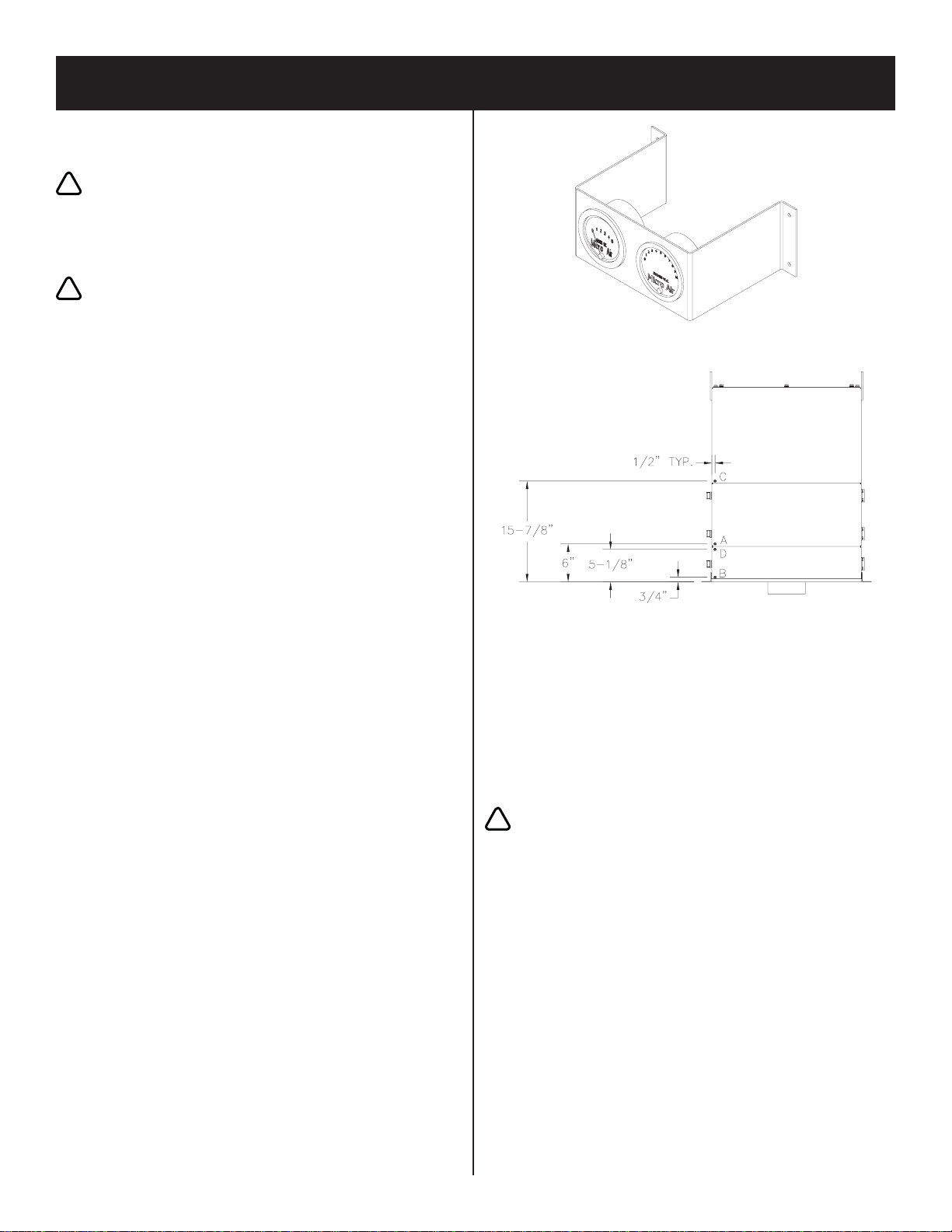
GAUGE INSTALLATION:
1. Mount the gauges in the gauge bracket (Fig 3).
2. Drill 3/8” dia. holes in the cabinet (Fig. 4) and
insert P1050 gromet.
3. Connect P2806 tubing from the hole labeled “A”
(Fig 4) to the port labeled “LOW” on the 0-5”
minihelic.
4. Connect P2806 tubing from the hole labeled
“B” (Fig 4) to the port labeled “HI” on the 0-5”
minihelic
5. Connect P2806 tubing from the hole labeled “C”
(Fig 4) to the port labeled “LOW” on the 0-10”
minihelic.
6. Connect P2806 tubing from the hole labeled
“D” (Fig 4) to the port labeled “HI” on the 0-10”
minihelic.
OPERATION:
1. To start air cleaner, turn the knob to the position
labeled “ON”. To stop the unit turn the knob to
the position labeled “OFF”.
1.
2.
3.
4.
5. GENERAL MAINTENANCE:
1. No lubrication is required for the motor because it
is a permanent pre-lube design. Excessive dirt / oil
should be periodically removed.
CHANGING FILTERS:
CAUTION: Always turn the air cleaner
off before changing filters.
1. The MM600 is equipped with dual filter gauges
(0-5” for pre-filter and 0-10” for main filters).
The pre-filter should be removed, cleaned and
inspected when the gauge labeled pre-filter reads
2” W.C. The main filter should be removed and
replaced when the gauge labeled main filter reads
between 6” W.C. and 8” W.C. (depending on
desired air flow).
2. The pre-filters should be cleaned in a detergent
solution to remove dirt and oil residue.
3. Rinse the pre-filters thoroughly with water, shake
dry and replace in the unit.
4. Re-start the air cleaner.
!
!
Figure 3
Figure 4
!

208/230/460 Volt Wiring Diagram
MICRO AIR®MM600
CLEAN AIR SYSTEMS

ITEM PART NO. DESCRIPTION
1 P2320 2 HP Motor
2 38785-03 Motor Mounting Plate
3 P2302 Blower Wheel, Housing and Inlet Plate
4 P7321 Square Mist Max Filter
5 P7292 / P1828 & P7309 Mist-X Pre-Filter / Baffle & Mesh Pre-Filter
Not Shown P2221 0-5” W.C. Mini-Helic Gauge
Not Shown P7297 0-10” W.C. Mini-Helic Gauge
Not Shown P7322 99.97% Optional Hepa Filter
MM600 PARTS LIST
L2601-1
2009
MM600 MICRO AIR®
CLEAN AIR SYSTEMS
Popular Ventilation Hood manuals by other brands


Kenmore
Kenmore 233.55012000 Use & care guide

Jenn-Air
Jenn-Air JXU9130HP Installation Instructions and Use & Care Guide

IKEA
IKEA LUFTIG manual

Franke
Franke FDPA 904 XS LED0 Instructions for use and installation

NEFF
NEFF D5655X1GB User manual and installation instructions

Bertazzoni
Bertazzoni Professional Series User instructions

AEG
AEG DEI 60 PL 2 Instructions for installation and use

NEFF
NEFF D8662N0GB installation instructions

Zanussi
Zanussi Supertredilwash 641399 Brochure & specs

Broan
Broan Best IS102 Series Specifications

Kleenmaid
Kleenmaid RH17 Instructions for use and warranty details

Whirlpool
Whirlpool AKR 968 IX Instructions for use