MILANDR MILUR 107 User manual

Milandr, Inc.
Milur 107 Operation Manual
Operational Manual for Milur 107 Smart Meter
Page 1 of 16
MILUR 107 ELECTRIC METER OPERATION
MANUAL
Purpose: This manual, intended for studying Milur 107 Smart Electric Meter (hereinafter - the Meter) and
the main guiding document during operation (Installation, Usage, technical information, and maintenance).
The Instruction Manual Contains:
• Description of the Meter and its components;
• Technical Specifications and other information necessary to ensure capabilities of the meter;
• Guidance for dealing with the meter;
• Safety Information and best practices;
• Installation Instructions;
• Manual & Remote operation details;
Note:
The manufacturer is continuously upgrading the meters. The meters may have minor differences
not reflected in the operation manual.

Milandr, Inc.
Milur 107 Operation Manual
Operational Manual for Milur 107 Smart Meter
Page 2 of 16
TABLE OF CONTENTS
1. Product Description
2. Technical Details
3. Safety Information
4. Conditions of Use
5. Environmental Considerations
6. Installation Procedure
7. Manual Operation
8. Remote Operation
9. Measures to prevent unauthorized access
10. Tariff Schedule
11. Load Control
12. Maintenance
13. Software Identification

Milandr, Inc.
Milur 107 Operation Manual
Operational Manual for Milur 107 Smart Meter
Page 3 of 16
MILUR 107 SMART ELECTRIC METER
Product Description
Description
The Milur 107 is a single-phase smart meter, ideal for measuring
electrical energy consumption. The Meter is direct pass-through, so
it does not require current transformers. It is equipped with a built-
in ARM microcontroller and contains a variety of interfaces for
exchanging information with external devices.
The meter is designed to account for active and reactive electrical
energy in two-wire networks of alternating current with a rated
voltage of 110V/230V and frequency 50/60 Hz.
The basic (max) load current is 5 (80) A.
The Meter, depending on its design, is made for both indoor and
outdoor applications. The outdoor enclosures are protected by IP51
and IP54 protection.
A Meter with reduced terminal covers requires additional protection
from direct water ingress.
The measuring unit of the outdoor meter has an IP20 degree of
protection. The Meter is intended for the organization of one and up
to four tariffs of differentiated accounting, both by time of day and
by the level of consumed electricity and power.
Electrical Energy Consumption is shown on the LED (liquid crystal
display) screen on the front of the meter.
The meter has two pulse outputs galvanically separated from the
network for recording active and reactive electrical energy. The
meter can be operated both autonomously or as part of an
automated system of commercial metering of electric power of
ASKUE, with a pre-established program and the possibility of setting
(correcting) the corresponding tariff schedule.
Meter Modifications
The Meter can be equipped with a multitude of modifications, including:
- Additional communication interface (RS-485, PLC, PLC.G3, RF868, ZigBee);
- Hardware load disconnection;
- Additional current sensor in the "zero" wire;
Milandr, Inc.
Milur 107 Operation Manual
Operational Manual for Milur 107 Smart Meter
Page 4 of 16
MILUR 107 SMART ELECTRIC METER
Technical Details
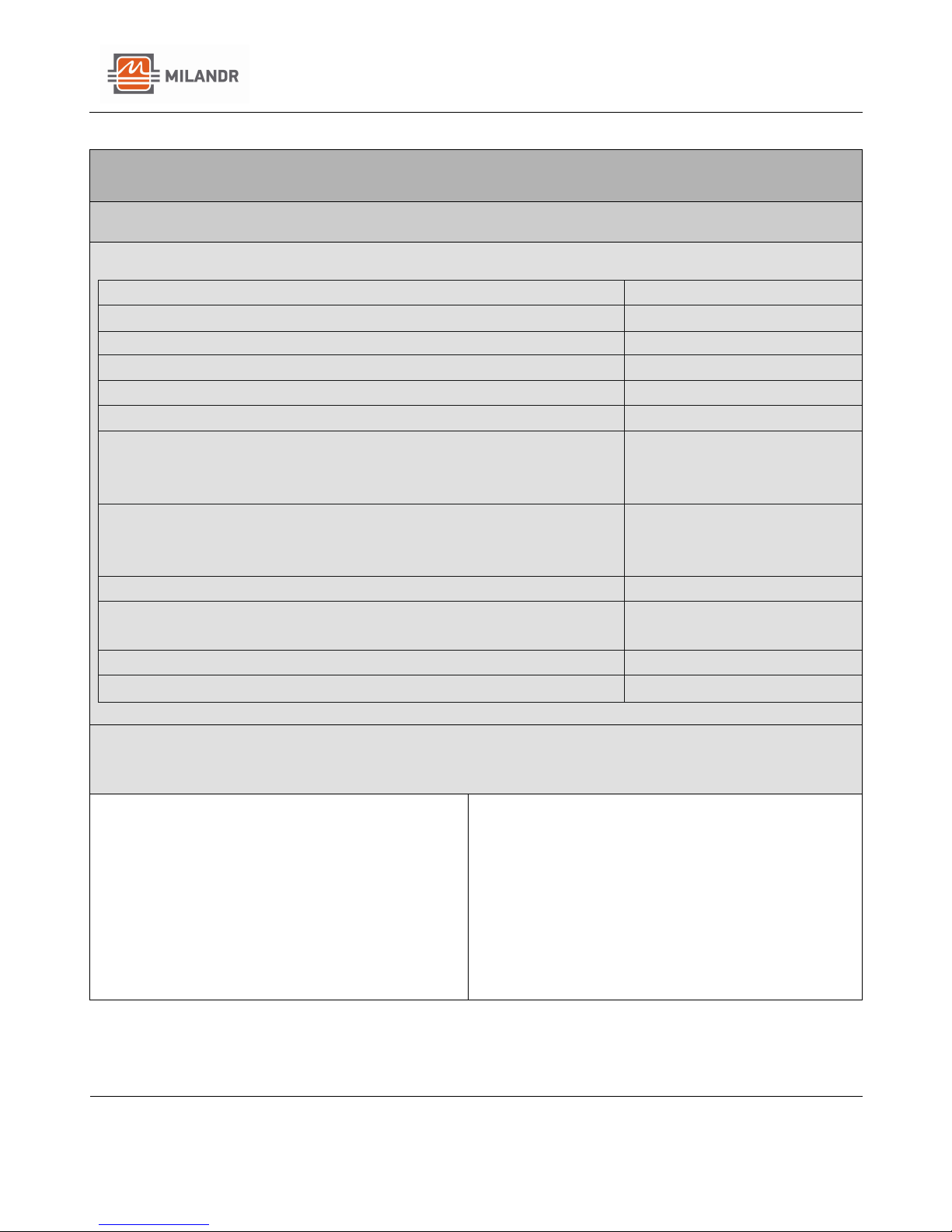
Specifications:
Accuracy Class for active energy
1
Accuracy Class for reactive energy
2
Rated Voltage, V
110 / 230
Absolute limits of working voltage, V
0-265
Current, A
5 (80)
Nominal Frequency, Hz
50/60
Starting current (sensitivity) (no less than), A
- active energy
- reactive energy
0.02
0.025
Operating Temperature range, °F
- indoor Installation
- outdoor Installation
-40 to +158
-58 to +158
Number of tariffs
Up to 4
Accuracy of the build-in clock with the meter on at standard
temperature, s/day (no less than)
±0.5
Average Error-free runtime, hours
220000
Average meter lifetime, years
30
Features:
Reliability and Quality:
MDR32F23QI Chip with 32-bit RISC-core
Cortex-M0
Protection Against Theft:
Electronic log of tamper attempts
Mounting:
DIN Rail Mounting
Fire Safety:
Made of non-combustible Materials
Operating Temperature:
Operates between -40 °F and +158 °F

Milandr, Inc.
Milur 107 Operation Manual
Operational Manual for Milur 107 Smart Meter
Page 5 of 16
MILUR 107 SMART ELECTRIC METER
Safety Information
Safety Information
1. Before operation, it is necessary to familiarize yourself with the
operational documentation of the meter.
2. All work regarding the installation, maintenance and repair of the
meter should be done by persons who have received safety training
and who have worked with a voltage of up to 1000 V.
3. All work related to the installation of the meter must be carried
out on a disconnected network. The circuit breaker should be easily
accessible, located in the immediate vicinity of the meter and
included in the installation of the electrical wiring of the facility.
NOTE - Installation should always be performed by a qualified electrician.
The bus wire and interface connecting diagrams are printed inside the
covers.
Please contact us with any additional installation or maintenance
questions; The detailed specifications, installation and programming
instructions are available online at: www.milur.com
Conditions of Use
1. The voltage applied to the meter must not exceed 265V.
2. The current in the meter's series circuit must not exceed the
specified maximum value of 80 A.
3. Remove the meter from its packaging and perform an external
inspection.
4. Make sure that there is no visible damage to the body or
protective covers for the terminal blocks. Check for the
presence and quality of the seals.
5. Install the meter at the place of operation, remove the
protective covers of the terminal blocks and connect the
voltage and current circuits in accordance with the scheme on
the protective cover.
NOTE - The connection of the internal installation meter to the mains must be
carried out via switch in the immediate vicinity of the meter in an easily accessible
place for the operator. The switch must be marked as a trip device for the meter.
ATTENTION: connection of voltage and current circuits should be carried out with
the power supply de-energized.
Milandr, Inc.
Milur 107 Operation Manual
Operational Manual for Milur 107 Smart Meter
Page 6 of 16
MILUR 107 SMART ELECTRIC METER
Environmental Considerations
The meter is designed to work under the following
conditions:
•Temperatures from -40 to + 158 °F
•Relative humidity up to 80% at a temperature of 86 °F
•Atmospheric pressure from 84 -106.7 kPa
Installation Procedure
1. To begin, remove the Meter from the transport package and
make a visual inspection.
2. Verify that there is no visible damage to the body and
protective covers contact pads, as well as availability and
safety of seals.
3. Install the meter in the field of operation, remove the
protective covers contact pads and connect the voltage and
current circuits in accordance with the scheme, shown on
the protective cover
4. Connecting the internal installation meter to the mains
produce through a switch located in the immediate vicinity
of the meter in an easily accessible place for the operator.
The switch must be marked as trip device for the meter.
When using the meter as part of automated AMR systems
you must connect and configure the appropriate interface:
• Connect the RS-485 interface circuits in
accordance with the scheme specified in
Appendix D, observing the polarity of the
connection;
• No connection is required when using PLC and RF
interfaces. Required set up the device according
to this manual
5. Install the protective covers on the terminal block for
connecting the network wires and on a shoe for connection
of impulse outputs and the interface, fix with two screws
and seal.

Milandr, Inc.
Milur 107 Operation Manual
Operational Manual for Milur 107 Smart Meter
Page 7 of 16
MILUR 107 SMART ELECTRIC METER
Installation Procedure
(Continued)
6. Switch on the mains voltage and make sure that the meter
has turned on. On the meter’s display, the active energy
consumption, instantaneous values of current capacity,
network voltage, current, time, and date are displayed.
If there is a load, the LED indicators flash. According to the
tariff schedule, one of the symbols
➊, ➋, ➌, ➍ , denoting the current tariff number.
7. Make a note in the form for the date of installation and the
date of commissioning.

Milandr, Inc.
Milur 107 Operation Manual
Operational Manual for Milur 107 Smart Meter
Page 8 of 16
MILUR 107 SMART ELECTRIC METER
Manual Operation
Summary
Information from the Meter can be read both in manual control mode
and remotely, through any of the available interfaces. The displayed
options are grouped into 4 cycles. Switching between options in the cycle
is made by short pressing the button "Option". When Pressing the
"Menu" button switches between cycles. If not Press the buttons for one
minute, the meter automatically switches to the first display cycle (user
menu), and the external Meter display unit installation is completely
turned off, it is switched on for a short time by pressing one of the
buttons.
Upon power-up, the meter measures the power, determines the tariff
number according to the tariff schedule of the current (or holiday) day of
the week, starts to register energy in the current tariff and is set in the
first cycle display (user menu).
First Display Cycle (User
Menu)
In the user menu on the Meter indicator is cyclically displayed
(depending on the screens included):
• Total consumption of active energy for all tariffs;
• Consumption of active energy at tariffs 1, 2, 3, 4;
• Active power;
• Voltage of the network;
• Current;
• The current date;
• Current time; is the frequency of the network.
If there is a load, the LED indicators flash periodically.
The duration of each option indication is 10 s by default. Display
time can be changed programmatically. The amount of energy
consumption is presented in the format ХХХХХX.ХX,
Where: ХХХХХX.ХX – is the value (000000.00…999999.99).

Milandr, Inc.
Milur 107 Operation Manual
Operational Manual for Milur 107 Smart Meter
Page 9 of 16
MILUR 107 SMART ELECTRIC METER
First Display Cycle (User Menu)
Continued
The value of the current day of the week, day, month, year is
displayed in the format: dd.mm.yy,
Where:
dd – the number of the month (01…31);
мм – month (01…12);
YY - the last digits of the year (00 ... 99).
Example output: July 18, 2003 (July 18, 2003).
When the date is displayed, the word "date" is displayed on the
screen.
The current time value is displayed in the following format:
hh:mm:ss,
Where:
hh − hours (00…23);
мм − minutes (00…59);
ss − seconds (00…59);
When time is displayed, the word "time" is displayed on the screen.
The power value is displayed in the following format: ХХХХХX.ХX,
Where: XXXXXX.XX is the value (000000.00 ... 999999.99).
The size of the displayed power is Watt.
In this case, the indicator "W" is displayed.
The voltage value is displayed in the following format: ХХХХХX.ХX,
Where: XXXXXX.XX is the value (000000.00 ... 999999.99).
The size of the displayed voltage value is Volt. In this case, the
indicator "V" is displayed.
The current value is displayed in the following format: ХХХХХX.ХX,
Where: XXXXXX.XX is the value (000000.00 ... 999999.99).
The dimension of the displayed voltage value is Ampere. In this
case, the indicator "A" symbol is displayed.

Milandr, Inc.
Milur 107 Operation Manual
Operational Manual for Milur 107 Smart Meter
Page 10 of 16
Second Display Cycle
In the second display cycle, the following Options are displayed:
• Total current active energy value for all tariffs;
• Current value of active energy at tariffs 1, 2, 3, 4;
• Total current value of reactive energy for all tariffs;
• Current value of reactive energy at tariffs 1, 2, 3, 4;
The "Option" button on the front panel of the Meter cycles the
displayed parameters. When you press the "Menu" button on the
front panel of the Meter, the display cycle switches to the next.
The dimension of the displayed energy values - kW · h (kVar · h). At
the same time, the
"kWh" (kVar h) symbol is displayed in the LCD display.
Third Display Cycle
The following options are displayed in the third display cycle:
• Instantaneous value of active power;
• Instantaneous reactive power;
• Instantaneous full power;
• Instantaneous voltage value;
• Instantaneous current value;
• Instantaneous frequency value;
• Power factor.
The "Options" button on the front of the Meter cycles the display
parameters. When you press the "Menu" button on the front panel
Meter, the display cycle switches to the next.
- The dimension of the displayed power value is "W" (VAR, VA).
On the LCD the symbol “W” is displayed.
- The dimension of the displayed value is voltage-B. on the LCD
the symbol "V" is displayed.
- The dimension of the displayed current value is A. on the LCD the
symbol "A" is displayed.
- The frequency of the displayed frequency is Hz on the LCD the
symbol “hz” is displayed. The power factor has no dimension. on
the LCD the symbol "PF" is displayed.

Milandr, Inc.
Milur 107 Operation Manual
Operational Manual for Milur 107 Smart Meter
Page 11 of 16
Fourth Display Cycle
The following Options are displayed in the fourth display cycle:
• The current date;
• Current time;
• Backup battery voltage;
• Network address of the Meter;
• Software version;
• Identifier of the metrological part of the software;
The "Options" button on the front of the Meter cycles the display
Options. When you press the "Menu" button on the front panel
Meter, the display cycle switches to the next.
The voltage of the backup battery is displayed in the format:
P1 X.XX, Where: X.XX is the value (0.00 ... 9.99).
The size of the displayed voltage value is Volt. In this case, the
indicator on the LCD displays the "V" and "P1" symbols.
The network address of the Meter is displayed in the format:
P2 ХХХ, Where: XXX is a byte decimal number that displays the
Meter address in decimal form.
When the network address is displayed, the symbol "P2" is
displayed.
The software version is displayed in the format P3 Х.ХХ,
Where: XXXX is a four-byte array in ASCII code.
When the software version is displayed the symbol "P3" is
additionally displayed.
The identifier of the metrological part of the software is displayed
in the format: P4 ХХХХ,
Where: XXXX is a two-byte hexadecimal number that represents
the control the amount of the metrological part of the software in
hexadecimal form.
When displayed the identifier of the metrological part, the symbol
"P4" is additionally displayed.

Milandr, Inc.
Milur 107 Operation Manual
Operational Manual for Milur 107 Smart Meter
Page 12 of 16
MILUR 107 SMART ELECTRIC METER
Remote Operation
Summary
To exchange information with a Meter via RS-485 interfaces and
optical port you can use universal interface converters (for
example, PI-2 and USO-2). To exchange information with meters
equipped with PLC modems, ZigBee and RF it is necessary to use
the interface converter "Milur IC" TSCN.468369.500. To exchange
information with meters equipped with modems RF868 and PLC.G3
/ RF868 use data collection and transmission device of the
TSCN.424170.001. The converter is connected to the USB port of
the computer and Configured with the Milur Meter Configurator
software for a specific type modem (interface). The connection with
the Meter is established after specifying the corresponding fields of
the Meter address program, access level, password level access,
and the number of the virtual COM-port on which the converter
was installed. If all the options are specified correctly and the Meter
is in the network coverage area, clicking the "Open communication
session" button will establish the connection with the Meter. A
detailed description of the organization of the network is located in
the operating instructions (user manual) on the inverter interfaces
"Milur IC".
Actions to change the modes and options of the Meter should not
be carried out arbitrarily and should be strictly controlled by
operating organizations. Access to the meter should be protected
from malicious tampering. Some Measures of protection from
unauthorized actions with the Meter is provided, such as non-
erasable tamper logs. When working with the serial interface we
recommend providing password protection for all possible
commands.

Milandr, Inc.
Milur 107 Operation Manual
Operational Manual for Milur 107 Smart Meter
Page 13 of 16
Remote Operation (Continued)
The set of allowed commands is divided into group and individual.
The Meter is provided with two levels of access: 1st level of access
"user", and 2nd level of access "administrator". For each access
level, a separate password of six characters (six bytes) is allowed.
For any discrepancy between the meter password/address and the
password/address specified in the command, the command will be
interpreted as wrong and will be rejected by the Meter. In case of
incorrect entry of the password three times the Meter locks the
recording channel for 30 minutes. Session lock time is
programmable through available interfaces.
Each Meter is given the following default passwords and addresses:
- The password of the first level:
FF FF FF FF FF FF (255 255 255 255 255 255);
- The password of the second level:
FF FF FF FF FF FF (255 255 255 255 255 255);
- Exchange rate 9600/8N/1;
- The Meter address is 255 or the last three digits of the serial
number are less than 255,
- The passwords and addresses can only be changed via a serial
interface.
When operating Meters after changing passwords and / or
addresses, pay special attention to the preservation (memorization)
of the latter. Recovery is possible only through the violation of the
Meter seal.
Measures to Prevent
Unauthorized Access
In addition to password protection, there is a hardware jumper for
protection calibration factors of the Meter. Access to calibration
factors is possible only with violation of the Meter seal.

Milandr, Inc.
Milur 107 Operation Manual
Operational Manual for Milur 107 Smart Meter
Page 14 of 16
Tariff Schedule
The meter measures consumed energy with four tariffs. Switching
from one tariff to another is made automatically in accordance with
the specified tariff schedule. The tariff schedule is set by the
interface for each from twelve months. The tariff schedule provides
for 8 tariff zones. The tariff zone provides the time for switching to
another tariff and the number of the new tariff. Tariff switching can
be set for the following days: business day, holiday, Saturday, and
Sunday. Switching of the tariff schedule should be recorded
consecutively, without omissions. The switching time for the next
tariff schedule must be set strictly in order to increase the time. If
the switching time in the current record will be less than in the
previous record, then the current recording rate will be set. The
records of the tariff schedule for the day should start from the
beginning of the day. In the first record the tariff schedule for the
day should be set to 00:00. Changing the tariff schedule is possible
only at the access level "administrator".
Load Control
To perform this function, the impulse output of active energy can
be transferred to three additional modes: "load on", "load off "and"
automatic control ". When the "load on" function is selected the
pulse output will be in the load on state. When choosing function
"load off", the pulse output will be periodically set to load
disconnected status. The "automatic control" function allows
monitoring of the load power. To perform this function, you must
specify threshold of automatic control, for example, 2 kW.
Automatic control threshold load is the average value of the power
averaged over the interval integration of the meter's power profile.
When the load exceeds this limit, the pulse output will be
transferred to the "load disconnection" function. Re-activation of
the load is done by the command on the interface. Meters with
integrated load-shedding relays enable load on / off (selection of
functions of the built-in load control relay tab "Limits") in the
modes "Load is always on", "Load constantly off ", “Automatic load
control", “Semi-automatic control load”. Re-enabling the load in
semiautomatic control mode is possible only through the interface
and by pressing any of the meter buttons. In the "Automatic load
management" mode, re-enable is performed automatically and at
the end of the current profile averaging interval power (at the end
of the current half-hour interval.

Milandr, Inc.
Milur 107 Operation Manual
Operational Manual for Milur 107 Smart Meter
Page 15 of 16
Maintenance
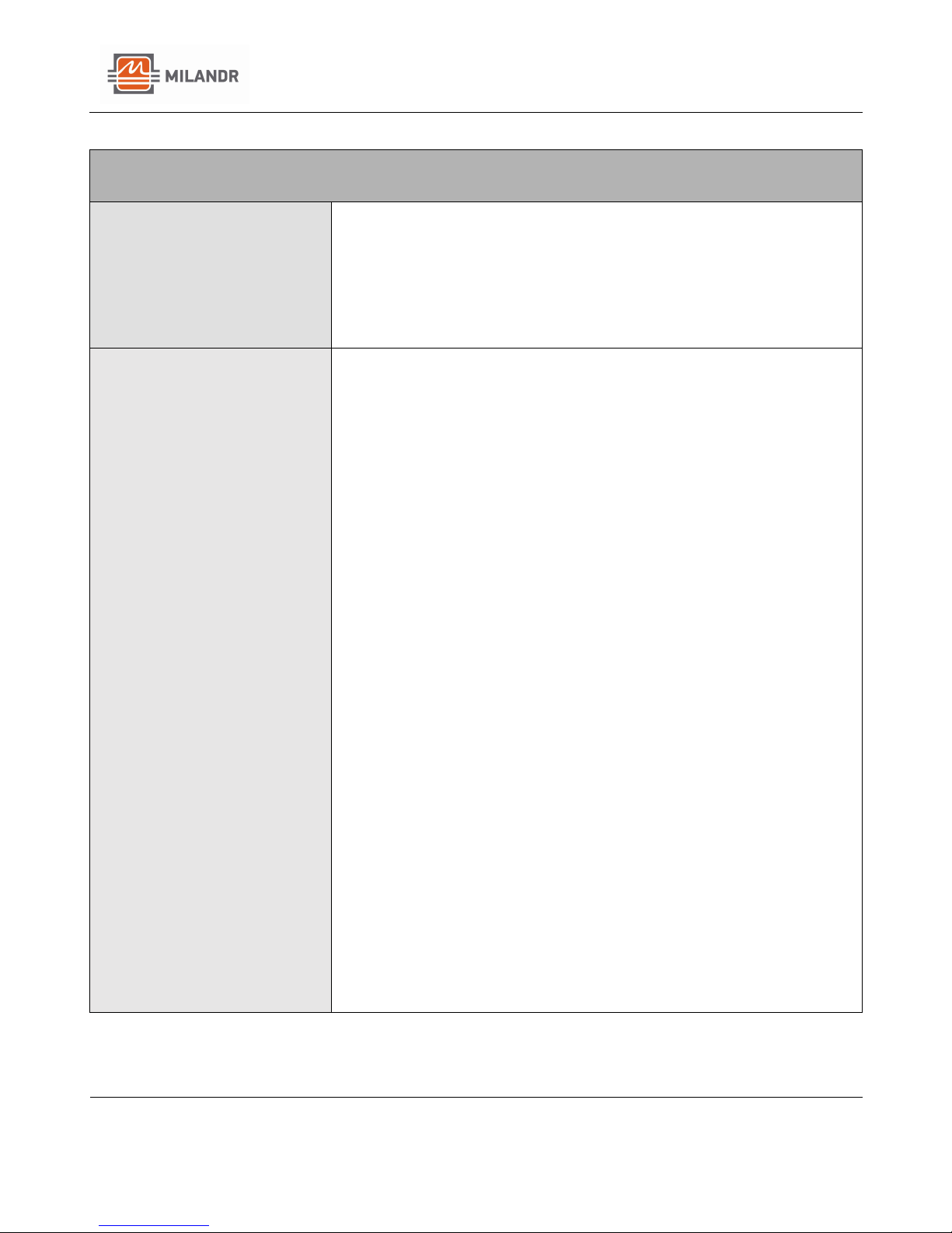
List of maintenance work, as well as frequency maintenance are
given in table 5.
Таble 5
List of Maintenance Work
Periodicity
Dust Removal form the housing and
front of the meter
*
Checking the reliability of
power and interface chains of
the meter
*
Checking the voltage on the
built-in lithium battery
*
Function Check
*
* In accordance with the schedule of preventive maintenance of
the operating organization
ATTENTION: THE WORK MUST BE CONDUCTED WITH A
CONNECTED NETWORK!
The dust should be removed from the meter surface by a clean, soft
wipe rag. To check the reliability of the power and interface circuits
of the meter you need to:
• Remove the seals from the protective covers of the terminal
blocks, and unscrew the fastening screws and remove the
protective covers;
• Remove dust from the terminal blocks with a brush;
• Tighten the screws of the terminal block to fixing the power
and interface wires chains;
• Install the protective cover of the terminal block, fix it with
two screws and to seal.
The meter has a 3.6 V lithium battery type CR2032, providing long
lasting, reliable power. The meter periodically checks the battery
voltage. If the battery voltage falls below 2.6 V, the LCD display with
a frequency of 0.5 Hz, and the battery indicator symbol flashes.
In this case the battery must be replaced.

Milandr, Inc.
Milur 107 Operation Manual
Operational Manual for Milur 107 Smart Meter
Page 16 of 16
Software Identification
Identification of software, protection of the metrologically
significant part internal BY from unauthorized settings, deliberate
and unintentional interference is provided as follows:
Metrologically significant part of the embedded software has
following identification features:
• Software name - Milur 105.hex;
• Version number of the software: 5.00 and higher;
• The checksum of the metrologically significant part of the
software
• ("Digital identifier PO ") - 0x7S29.
• The algorithm for calculating the checksum is CRC16.
To verify the integrity of the software and its compliance, it is
provided a unique identification. Identification is carried out by an
external "Milur Meter Configurator" software via communication
interface after establishing a connection with the Meter.
The check can be performed in the following way:
Under the command ‘Read from Meter’ in the "Measurements"
tab, the device determines the version of the firmware, calculates a
checksum (Digital ID of the software), and provides additional
information in the following form:
• A model of the Milur Meter,
• Version of the firmware,
• Digital identifier of the software (checksum).
Conclusion on the authenticity of the metrologically significant part
of the software is taken from the comparison of the calculated
checksum of the embedded software with the value of the above
checksum.
Table of contents
Popular Measuring Instrument manuals by other brands

Schaller
Schaller FL2 user manual

Stanley
Stanley PB-5 instructions

Braun Messtechnik
Braun Messtechnik HZ 3 Mounting instructions

Diet Fast Forward
Diet Fast Forward KETO FAST FORWARD 2.0 user manual

Shodex
Shodex OHpak SB-2000 Series Operation manual

Reed Instruments
Reed Instruments R3525 instruction manual


PCB Piezotronics
PCB Piezotronics 3711E1125G Installation and operating manual

SMC Networks
SMC Networks IN574-95 Installation & maintenance manual

Milwaukee
Milwaukee T75 user manual

SMA
SMA SUNNY WEBBOX with Bluetooth installation guide

Luciol Instruments
Luciol Instruments LOR-200 user manual

iSystem
iSystem Infineon user manual