Mill-right MEGA V FS User manual

Page 1of 33
ASSEMBLY INSTRUCTIONS FOR THE MILLRIGHT CNC MEGA V FS
Version 1.02
For additional resources, see www.millrightcnc.com/resources
Be sure to check the resources page for the most updated assembly instructions.
The resources page has a parts picture guide to further assist you in assembly.
We have a big online community. Be sure to join in the discussion.
Facebook MillRight CNC User Group
Facebook MillRight CNC Mega V Group
MillRight CNC Forum at www.millrightcnc.proboards.com
Important safety rules for operating your MillRight CNC Mega V FS:
Never place your hands near a spinning end mill or bit. Keep your hands off the gear rack!
Always wear eye and ear protection while operating your machine.
Always run a dust collector or wear a mask while performing a milling operation.
Do not leave the machine unattended while running a milling operation.
Do not operate your machine while under the influence of alcohol or drugs.
Secure long hair and loose clothing so it is not caught in spinning mechanisms.
Ensure work pieces are properly secured before running a milling operation.
Keep a fire extinguisher nearby.
Visually inspect wires prior to power up to prevent short circuits.
The Mega V FS is a big, heavy machine. Plan on spending a full weekend in assembly and seeking help with moving or
flipping heavy assemblies.
We recommend using a blue thread locker on any fastener not secured with a lock washer or lock nut.
Page 2of 33
V-Wheels
Parts
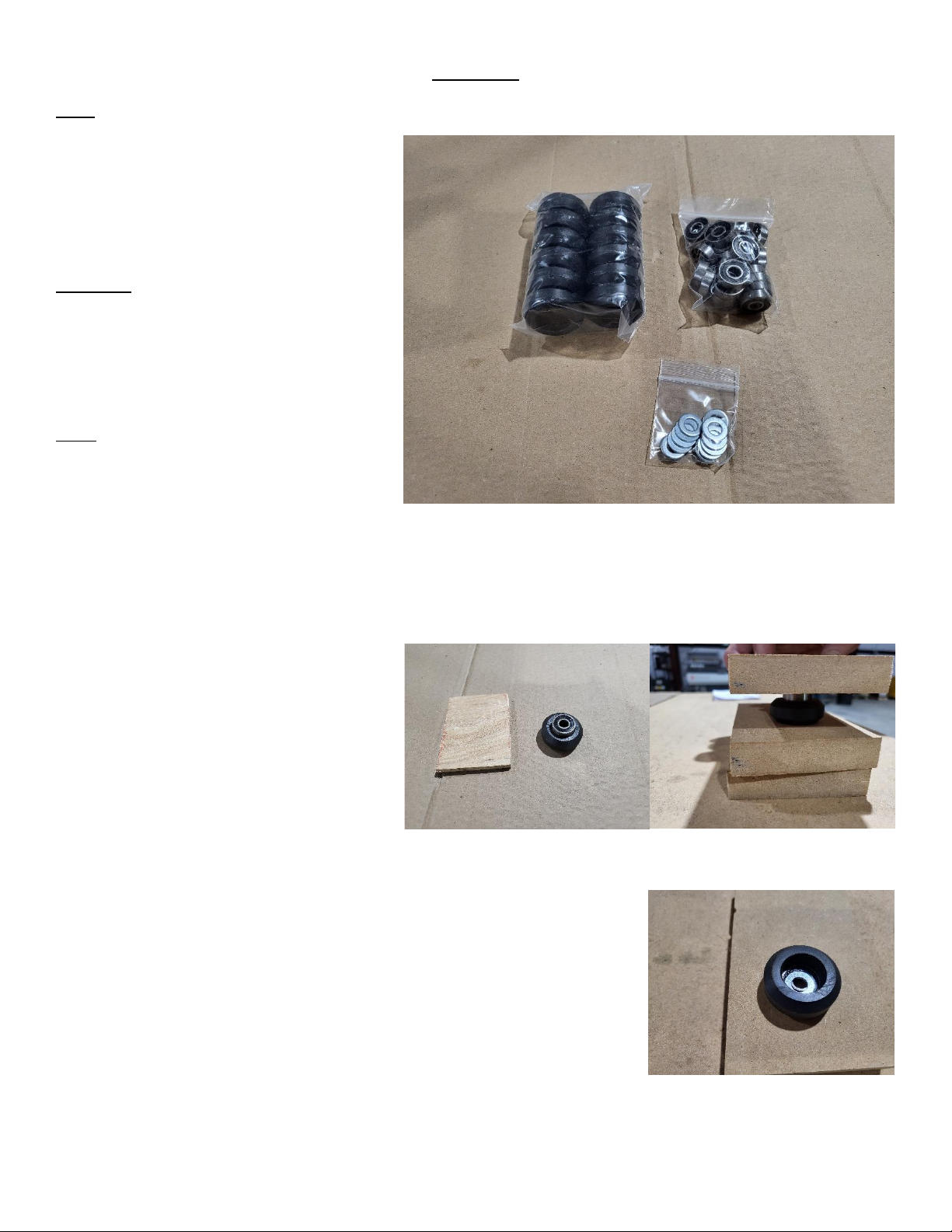
V-Wheel Kit
•V Wheel Body (12)
•608 Bearing (24)
Hardware
V-Wheel Kit
•M8 Washer (12)
Tools
Hard Surface
Something Flat to Press Bearing
Place the v-wheel body on a flat, hard
surface. Place (1) 608 bearing on top of the
v-wheel body. Using something flat, like a
scrap block of wood, press the bearing into
the v-wheel body.
Flip the v-wheel over. Place a M8 washer on the 608 bearing inside the v-
wheel. If you forget this step the bearing will not spin correctly. Fixing this
will be difficult.
Page 3of 33
Place a second 608 bearing on top of the v-wheel. Press the bearing into
the v-wheel using your impromptu tool. Pinch the inner races of both
bearings with your fingers and test that the v-wheel spins freely. Repeat
this process with the remaining v-wheel bodies. Set the v-wheels to the
side.
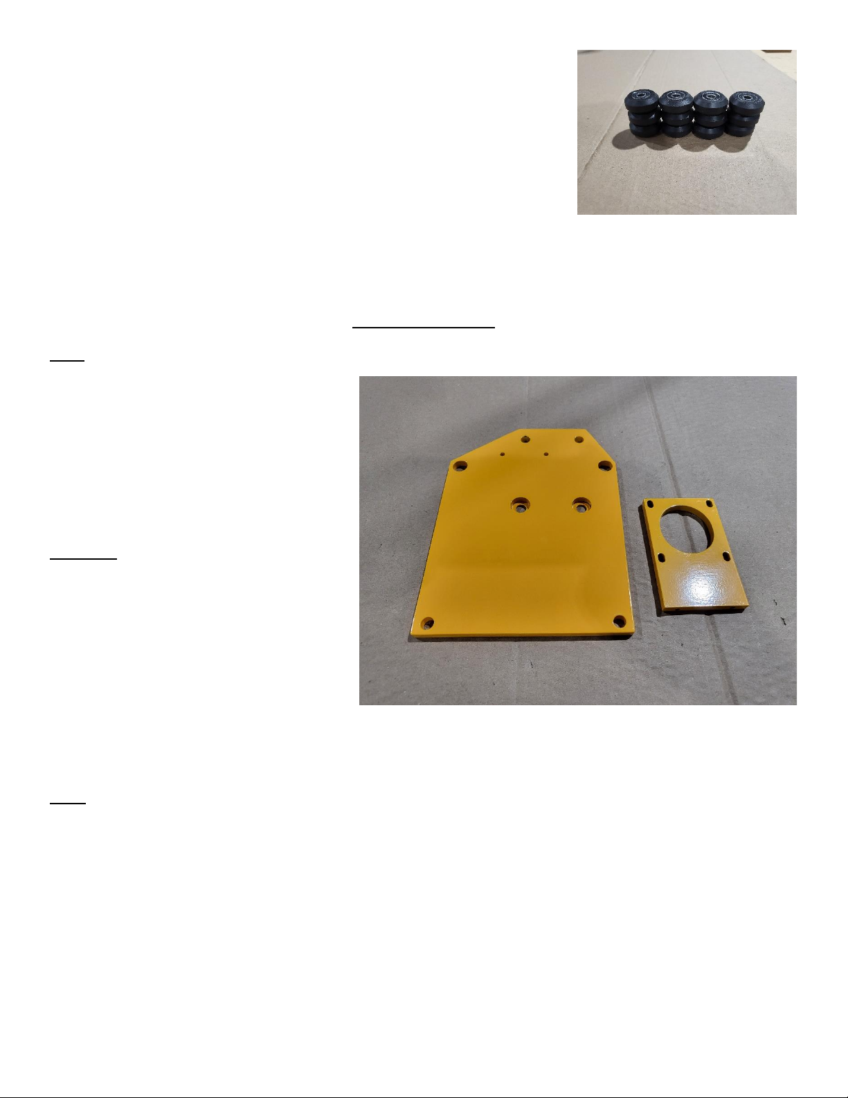
Gantry End Plates
Parts
Left Gantry End Plate
Right Gantry End Plate
X/Y Motor Mount (2)
Assembled V-Wheel (4)
Hardware
M4x12 Machine Screw (4)
M4 Split lock Washer (4)
V-Wheel Kit
•M8x40 Machine Screw (4)
•M8 Nylock (4)
•Eccentric Spacer (4)
Tools
Phillips-Head Screwdriver
Needle Nose Pliers
13mm Socket or Wrench

Page 4of 33
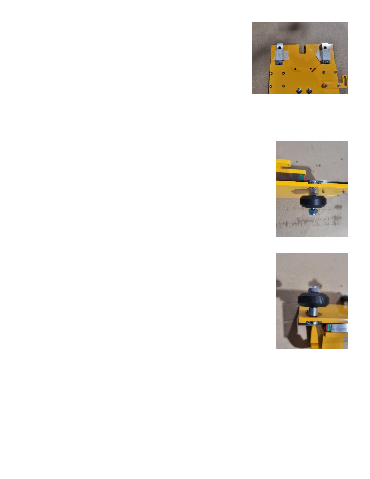
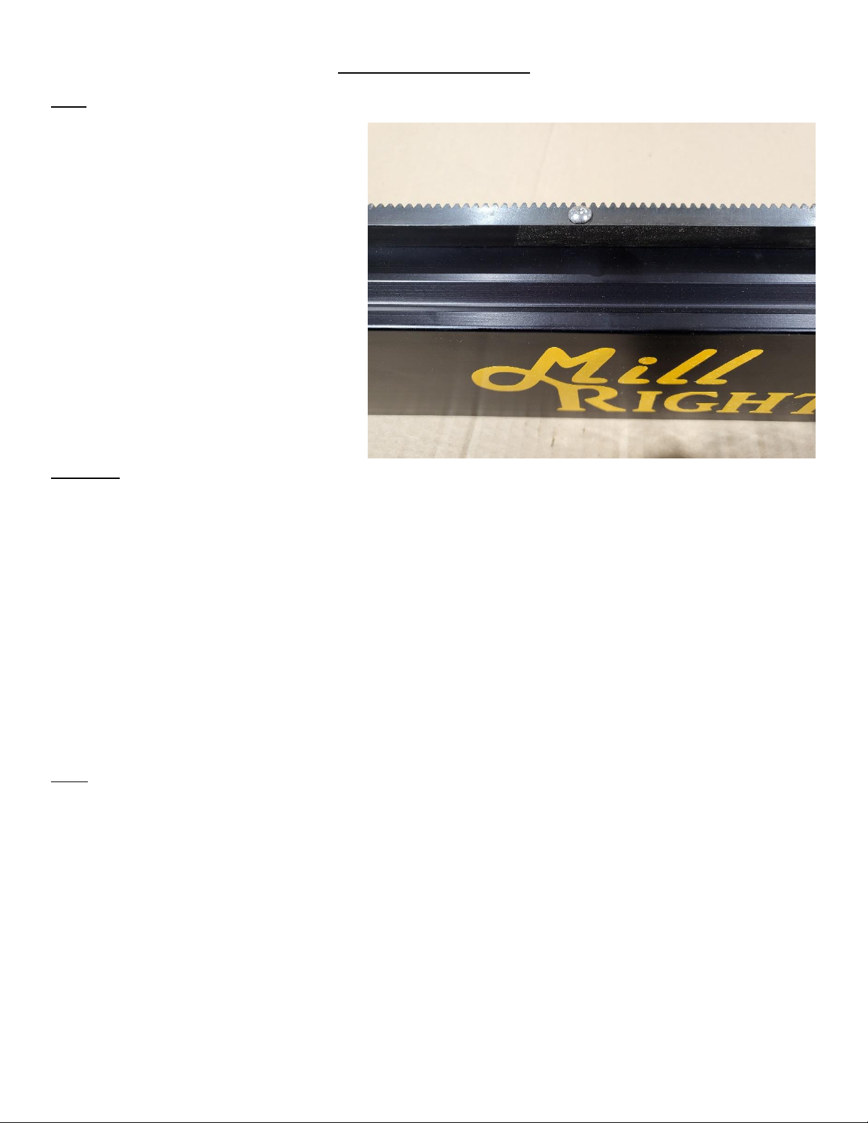
Locate the right gantry end plate. Place eccentric spacers
(2) in the large holes on the top of the gantry end plate.
The recessed pockets should be face up. Place a v-wheel on
a M8x40 machine screw. Spinning the wheel on the screw
will help to align the washer that is between the bearings.
Insert the M8x40 machine screw through the eccentric
spacer and secure with a M8 nylock nut. The v-wheel
should turn freely. The eccentric should turn with a 13mm
wrench. Repeat for the second eccentric spacer.
Repeat the process with the left gantry end plate. The recessed pockets on
the plate should be face up.
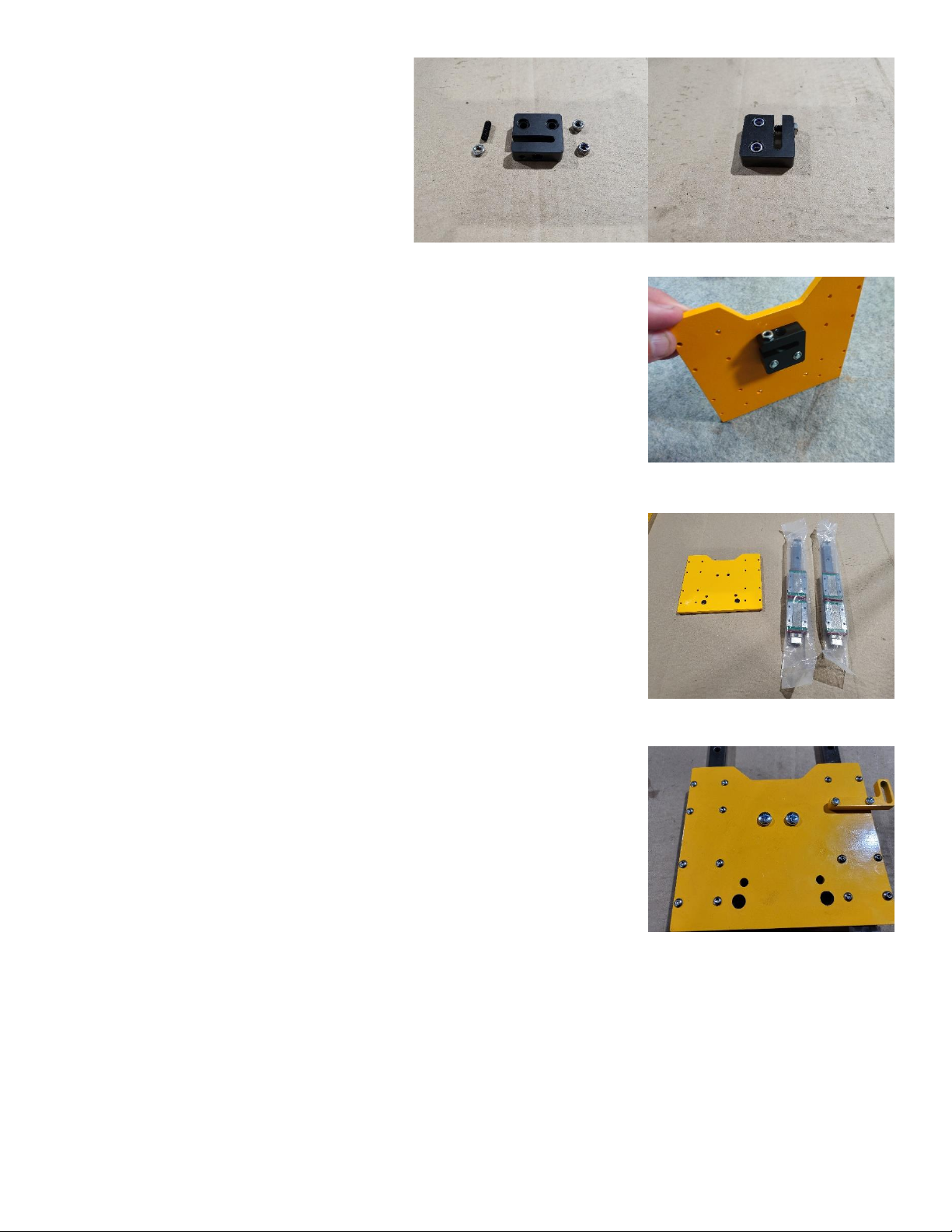
Locate a X/Z motor mount. The mount will
be installed on the same side of the gantry
end plates as the v-wheels. Place (2)
M4x12 machine screws with a M4 split lock
washer each through the back of the gantry
end plate (opposite the v-wheels) using the
two small holes located between the v-
wheels and install the motor mount.
Repeat the process on the other gantry end
plate. Place both to the side

Page 5of 33
Z Plate
Parts
Z Plate
Router Mount and Cap
Anti Backlash Nut with Hardware
Z Rail and Bearings (2) (inside box 2 single
wrapped 6060 extrusion)
Homing Kit
•Z Engager Bracket
Hardware
M3x10 Button Cap (14)
M3x16 Machine Screw (2)
M5x20 Machine Screw (2)
5/16x3/4 Button Cap Screw (2)
5/16x3/4 Button Cap Screw (2)
Tools
2mm Hex Key
2.5mm Hex Key
3mm Hex Key
3/16 Hex Key
Phillips-Head Screwdriver
Masking/Painters Tape
Page 6of 33
Locate the anti backlash nut (ABN). The ABN
will come with (2) M5 nylock nuts, a M5 grub
screw, and a M5 jam nut in the bag. Push
the nylocks into the hexagonal holes on the
face of the ABN with the nylon facing up.
Screw the grub screw into the top of the ABN
until it touches the bottom through the gap.
Cap the grub screw with the M5 jam nut. Place the ABN on the z plate and
secure using the (2) M5x20 machine screws. Make sure the nylocks can be
seen.
Locate the Z rails with bearings. The bearings will slide off the rails expelling
all ball bearings. Please proceed with caution. The rails will have plastic or
rubber blocks to keep the bearings from sliding off. Leave them in place
until told to remove them. If the blocks are not present, tape both ends of
the rails to keep the bearings from sliding off. Place the Z rails on a flat
surface with the bearings face up.
Place the Z plate on top of the bearings lining up the bearings with the 4-
hole groups on the corners of the Z plate. The ABN should be on the same
side of the Z plate as the bearings. Secure the Z plate to the bearings using
the M3x10 button cap screws. If you have purchased the Homing Switch
Option, Locate the Z engager bracket. Secure the bracket to the Z plate
with M3x16 machine screws using the two bottom holes of the 4-hole
group at the top right of the Z plate. The indention on the Z plate is the top.

Page 7of 33
Locate the router mount. Carefully turn
the Z plate on its side making sure the
bearings stay on the rails. Place (2)
5/16x3/4 button cap screws through the
back of the plate using the 2 large holes at
the bottom of the Z plate. Attach the
router mount to the Z plate and tighten the
router mount screws. Use (2)
5/16x1button caps to attach the router cap
to the router mount. Place the Z plate to the side.
X Plate
Parts
X Plate
Z Motor Mount
Screw Seat Plate
UHMW Screw Seat
178mm Lead Screw
Assembled V-Wheel (4)
4750 Motor (1)
Hardware
M5x16 Machine Screw (2)
M5 Nylock Nut (2)
M4x12 Machine Screw (6)
M4 Split Lock Washer (6)
M3x16 Machine Screw (6)
M3 Nylock Nut (6)
8x6.35 Coupler
V-Wheel Kit
•Eccentric Spacer (2)
•Standard Spacer (2)
•8x40 Machine Screw (4)
•M8 Nylock (4)
Page 8of 33
Tools
Phillips-Head Screwdriver
Needle Nose Pliers
2.5mm Hex Key
8mm Socket or Wrench
10mm Socket or Wrench
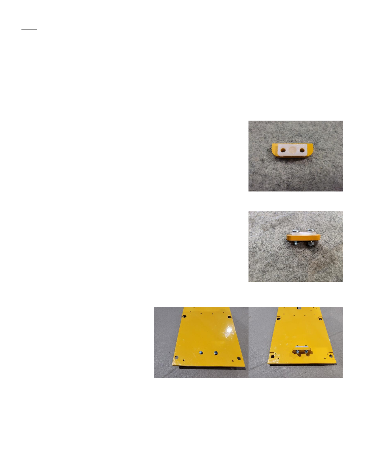
Locate your Z screw seat plate and UHMW screw seat. Place the UHMW
screw seat on top of the screw seat plate. Make sure the pocket of the
UHMW screw seat is facing up as shown.
Secure the UHMW screw seat to the screw seat plate using (2) M5x16
machine screws and (2) M5 nylock nuts. Do not over tighten or you may
deform the UHMW screw seat.
The front of the X plate is the face with the
recessed pockets. The top of the X plate is
the section with the “U” cutout, as shown
above. Place the screw seat plate on the X
plate near the bottom center set of holes.
Make sure the UHMW screw seat is
pointing towards the top of the X plate.
Place a M4 split lock washer on (2) M4x12
machine screw and insert the screws
through the back of the X plate to secure the screw seat plate to the X plate.
Page 9of 33
Place the Z plate on the front of the X plate. Line up the holes on the Z rails
with the (3) holes on each side of the X plate. (2) holes on the top on each
side and (1) hole on the bottom on each side. Carefully remove the top
plastic/rubber bearing block or tape on both rails. Insert a M3x16 machine
screw in the top hole on both rails and finger tighten a M3 nylock. Repeat
the process with the second hole on the rails. Carefully remove the
plastic/rubber bearing block or tape from the bottom of the Z rails. Insert a
M3x16 machine screw in the bottom hole on both rails and finger tighten a
M3 nylock.
Prop the X plate on its bottom using the router mount. Place (2) eccentric spacers
in the top, large holes on the back of the X plate. Insert (2) M8x40 machine screws
into the large holes in the front of the X plate and through the eccentric spacers.
Place an assembled v-wheel on the M8x40 machine screws and secure with (2) M8
nylock nuts.
Place (2) M8x40 machine screws in the large holes in the front of the X plate at the
bottom. Place standard spacers on the M8x40 machine screws, assembled v-
wheels, and secure with a M8 nylock nut.

Page 10 of 33
Locate the Z motor mount. Use the Z motor mount as a spacer for installing
the coupler onto the 4750mm motor. Tighten the pinch screw on the
6.35mm side of the coupler to attach the coupler to the motor shaft.
Thread the 178mm lead screw into the
ABN. Using (2) M4x12 machine screws with
M4 split lock washers, attach the Z motor
mount to the top of the X plate.
Locate the X/Y motor mount and lower the
Z plate to expose the two holes near the
center top of the X plate. Place a M4 split
lock washer on (2) M4x12 machine screws.
Insert the screws through the front of the X
plate and attach the X/Y motor mount to
the back of the X plate.

Page 11 of 33
Z Motor
Parts
4750mm Motor w/Coupler
Hardware
6.35mm Spacer (4)
M4x16 Machine Screw (4)
Tools
Phillips-Head Screwdriver
2.5mm Hex Key
Locate the 4750mm Motor with coupler. Place 6.35mm spacers (4) on the
mounting holes of the Z motor mount. Place the 4750mm motor with the motor
wire positioned to the back of the X/Z assembly, opposite of the router mount, onto
the spacers. Secure with (4) M4x16 machine screws.
Using a 2mm hex key, tighten the bottom screw of the coupler. This will
connect the coupler to the lead screw. Make sure the lead screw is fully
engaged with UHMW screw seat and apply light downward pressure. Place
the X/Z assembly to the side.
Page 12 of 33
Mega V Extrusion/Rack
Parts
1465 Mega V Extrusion w/Logo
2650 Mega V Extrusion (2)
Gear Rack Long (2)
Gear Rack Short
Drag Chain Mount (3)
Left Gantry End Plate
Right Gantry End Plate
X/Z Assembly
Y Mid-Span Support (2)
Hardware
Drop-In T Nut (13)
Large T Nut (32)
M5x12 Button Cap (9)
M5 Split lock Washer (13)
M5x20 Button Cap (32)
M5x25 Button Cap (4)
5/16x3/4 Button Cap (8)
Tools
Phillips-Head Screwdriver
10mm Wrench

Page 13 of 33
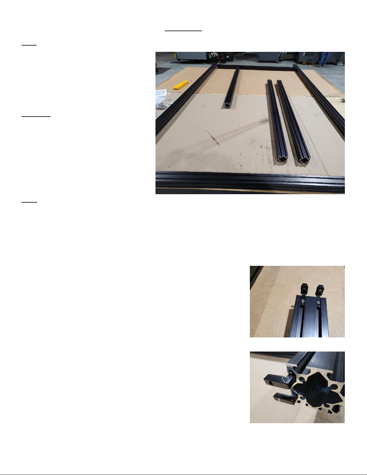
Get one section of long gear rack. Place M5x20 Button cap screw through
the holes (12) of the gear rack keeping the screws uniform. Spin a large t
nut a few turns on each screw. Leave the t nuts loose. Repeat process for
the remaining long gear rack and the short gear rack.
Slide the t nuts into the top of the Mega V extrusion with the gear rack
teeth pointing out from the extrusion, away from the v groove. Leave the
rack loose. The (2) 2650 Mega V extrusions will get the long rack. The 1465
Mega V Extrusion w/logo will get the short rack.
Designate one 2650 Mega V Extrusion as the right extrusion. Lay the
extrusion on it’s side with the rack teeth facing up. Locate a drag chain
mount. Place (3) drop-in t nuts in the groove on the opposite side of the
extrusion from the gear rack, near the left end of the extrusion. Put M5
split lock washers on (3) M5x12 button cap screws. Position the drag chain
mount with the slot facing to the left and attach the mount to the extrusion
using the M5x12 Button caps with lock washers and the drop in t nuts.
Locate the 1465 Mega V Extrusion with the logo. Lay the extrusion on it’s
side with the logo down and the rack teeth pointing up. Locate (2) drag
chain mounts. Place (6) drop-in t nuts in the groove on the opposite side of
the extrusion from the gear rack, near the right end of the extrusion. Put
M5 split lock washers on (6) M5x12 button cap screws. Position the drag
chain mounts with the slot facing to the right and attach the mounts to the
extrusion using the M5x12 Button caps with lock washers and the drop in t
nuts.

Page 14 of 33
Locate the (2) Y mid-span supports. In the middle of the 2650 Mega V
extrusion (1325mm), opposite the rack, place (2) drop-in t nuts in each
extrusion. Place M5 split lock washers on (4) M5x25 button cap screws.
Attach the Y mid-span supports to the 2650 extrusion using the M5x25
button caps with split lock washers and the drop-in t nuts. Orientation of
the Y mid-span support does not matter.
Retrieve the X/Z assembly. The mount is the bottom of the assembly, and
the motor is the top. The v-wheels will pinch the outside of the Mega V
extrusion using the v shaped slots on the top and bottom. If the v-wheels
are too tight to slide on the extrusion, use a 13mm wrench to turn the
eccentrics until the assembly slides onto the extrusion. Slide the X/Z
assembly onto the same side of the 1465 extrusion as the logo. Set the
2650 extrusion to the side being careful not to bend the drag chain mount.
Retrieve the left end plate. On the left side of the extrusion, use (4) 5/16 x
3/4 button cap screws to attach the left end plate to the extrusion. Repeat
the process on the right side with the right end plate. The end plates should
extend more from the front of the extrusion than the back. Set the 1460
Gantry to the side being carful not to bend the drag chain mounts.
Page 15 of 33
Frame Top
Parts
2650 6060 Extrusion (2)
1465 6060 Extrusion (7)
Gusset (14)
Hardware
Inside Corner Joiner (28)
Corner Joiner Set Screw (56)
M5x8 Button Cap (56)
Drop-in T Nut (56)
Tools
3mm Hex Key
3/16 Hex Key
Square
Preload the set screws in the inside corner joiners. (2) Set screws for each
corner joiner. Screw them in from the inside of the v of the joiner. Make
sure the set screw is not sticking out the back (outside v) of the corner
joiner or they will not slide down the extrusion slots.
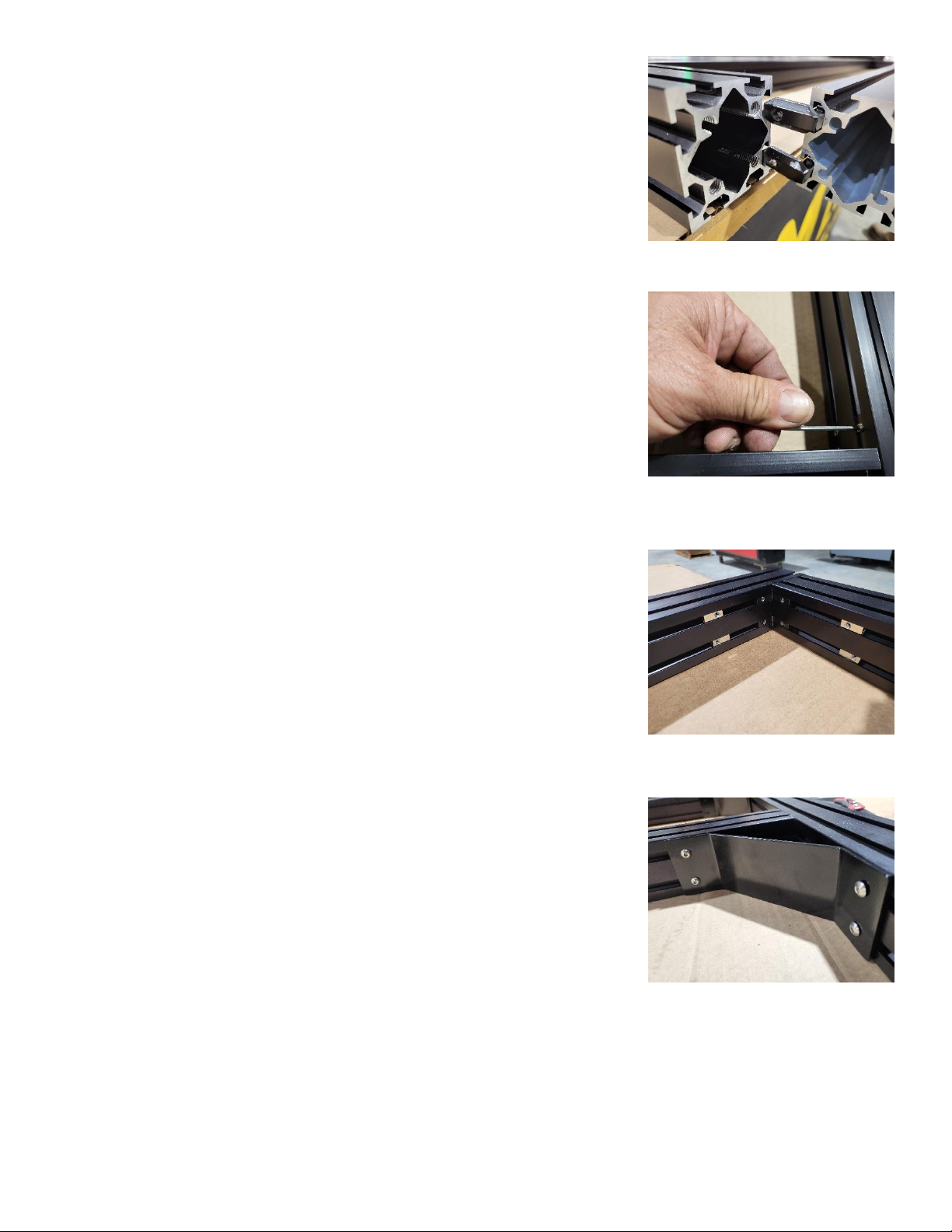
lat surface or table, lay out the (2) 2650 6060 extrusion with space for the
1465 extrusion between them. Take (1) 1465 extrusion and place (2) inside
corner joiners on each side of the extrusion (4 total for each 1465
extrusion). Make sure all corner joiners are on the same face of the
extrusion. The corner joiners will slide down the slot with one end in the
extrusion and stop at the edge of the extrusion with the other end. Make
sure the corner joiners stop at the edge of the 1465 extrusion. If they slide
down the slot, the orientation is wrong.
Page 16 of 33
Slide the 1465 extrusion into the 2650 extrusion. Repeat the process with
(5) of the remaining (6) 1465 extrusion. Keep the corner joiners pointing
the same way, towards the opposite end of the 2650 extrusion. The spacing
of the extrusion is about 371.66mm (14 5/8”) between the extrusions. The
last extrusion should be inserted into the other end of the 2650 extrusion
with the corner joiners pointing towards the opposite end.
Make sure the frame is square. Make sure the 1465 extrusion is flush with
the top of the 2650 extrusion. In the case of the front and rear 1465
extrusion, make sure the outside is flush with the ends of the 2650
extrusion. Tighten the set screws for the inside corner joiners.
The gussets will connect the 1465 extrusion to the 2650 extrusion on the
side opposite of the inside corner joiners. Place (2) drop-in t nuts, one in
each slot, on each end of the 1465 extrusions for a total of 4 drop-ins for
each extrusion. The front and back extrusions will have the gussets on the
same side as the inside corner joiners. Place (2) corresponding drop-in t
nuts in the 2650 extrusion for each set in the 1465 extrusion.
Using the M5x8 Button cap screws, attach the gussets to the 1465 Extrusion
and the 2650 extrusion. There will be (2) gussets for each 1465 extrusion,
one on either end, for a total of (14) gussets.
Page 17 of 33
Legs
Parts
Y End Plate (4)
760 6060 Extrusion (6)
Gusset (12)
Hardware
Large T Nut (8)
Drop-in T Nut (48)
Inside Corner Joiner (4)
Set Screw (8)
M5x8 Button Cap Screw (48)
M5x16 Button Cap Screw (8)
5/16x3/4” Button Cap Screw (16)
Tools
3mm Hex Key
3/16 Hex Key
Block/Brace (about 7”)
Square
Preload the set screws into the inside corner joiners, (2) for each joiner.
Slide (2) inside corner joiners into the top face of a 2650 extrusion, one
corner joiner in each slot. Repeat for the other 2650 extrusion for a total of
(4) inside corner joiners. Slide the corner joiners near the center of the
2650 extrusions.

Page 18 of 33
Pick up one end of the frame and block it up. If on a table, hang one end of
the frame (2650 extrusion) off the table. Locate a Y end plate. Using (4)
5/16x3/4 screws, attach the Y end plate to the end of the 2650 extrusion
using the 4 holes close to the smaller M5 holes. The smaller holes should
be pointed up. Repeat the process for the other 2650 extrusion. The Y end
plates will act as feet. Place something underneath to keep from scratching
the end plates. Block up the other end of the frame and repeat the process
for the other side. Check square throughout the process.
Slide (2) 760 leg extrusions onto the inside corner joiners, one leg extrusion
for each 2650. There are two tapped holes diagonally from each other on
one end of the 760 extrusions. Make sure the tapped holes on the 760
extrusions are pointing up. Leave the legs loose. The legs will need to be
adjusted when installing the subframe. Leave the legs near the center of
the 2650 extrusion.
Place (2) M5x16 button cap screws through
the outside of the y end plate and lightly
thread on a large t nut to each screw. Slide
a 760 leg extrusion onto the t nuts. Tighten
the M5x12 button caps while making sure
the leg is flush with the outside of the 2650
extrusion. Repeat for the other y end
plates and legs.
Place (2) drop-in t nuts in the grooves of the
legs, one in each slot, for each face of the
leg that is perpendicular to the 2650
extrusion and the front/rear 1450
extrusion. There will be (4) drop-in t nuts
for each leg total. Use M5x8 button caps to
install gussets on the legs using the drop-in
t nuts. There will be 2 gussets for each leg.
The 2650 Extrusion and the front/rear 1465 extrusion will need (2) corresponding t nuts for each set on the
legs.
Do not connect the middle legs to the 1465 extrusion. The middle legs will only be attached by gusset to the
2650 extrusion. Leave the gussets loose as the legs will need to be adjusted when installing the subframe.

Page 19 of 33
Subframe
Parts
1235 6060 Extrusion (4)
1465 606 Extrusion (3)
Gusset (14)
Foot Plate (6)
Leveling Feet (6)
Hardware
M5x8 Button Cap Screw (56)
5/16x3/4 Button Cap Screw (12)
Drop in T Nut (56)
Inside Corner Joiner (28)
Set Screw (56)
Tools
3mm Hex Key
3/16 Hex Key
Square
Place (2) drop-in t nuts, one in each slot, in the inside faces of each leg.
There will be (4) drop-in t nuts for each outside leg, and (6) drop-in t nuts
for each middle leg; (2) each on the left, right, and inside of the middle legs.
Attach gussets to the legs using M5x8 button caps and the drop-in t nuts.
There will be (2) gussets for each corner leg, and (3) for each middle leg.
The gussets should point up making a shelf for the subframe. The gussets
should be 430mm (about 17”) above the bed frame.

Page 20 of 33
Preload the set screws in the inside corner joiners. (2) set screws for each
corner joiner. Side the corner joiners, (2) on each side - (4) in total, in the
1456 extrusion oriented where they terminate against the end of the 1465
extrusion. Repeat this process with the 1235 extrusion.
Slide the 1465 extrusion into the front set, middle set, and rear set of legs. Sit them on the gussets. Slide the
1235 extrusion on the left and right, between the front and middle legs, and
the rear and middle legs. You may have to adjust the middle legs to allow
the 1235 extrusion to fit. Place (2) drop-in t nuts in each 1465 and 1235
extrusion to correspond with each gusset. Push the drop-in t nuts to align
with the gusset holes and secure with M5x8 button caps. Tighten all
gussets and inside corner joiner while checking square. Tighten the lower
gussets and inside corner joiners for the middle legs.
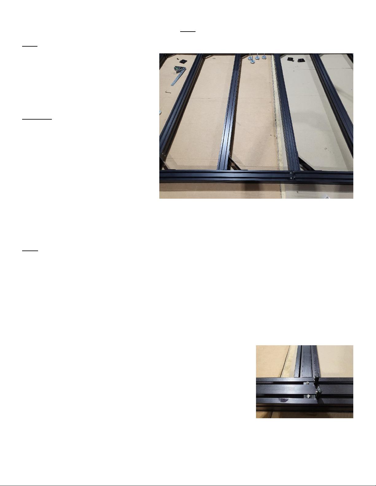
Locate the foot plate. Attach the foot plate
using (2) 5/16x3/4 button cap screws for
each leg. Locate the leveling feet. Screw
one into the center of each foot plate.
Get some help and flip the frame onto the leveling feet. Please do not attempt to do this without assistance
from others.
Table of contents
Popular Wood Router manuals by other brands

Silverline
Silverline SILVER STORM Series manual

Porter-Cable
Porter-Cable A15149 instruction manual

Mafell
Mafell LO 50 E Original operating instructions and spare parts list

Status
Status RH1200 Original instructions

Sears
Sears CRAFTSMAN 315.17380 owner's manual

Hitachi
Hitachi KM 12VC Instruction and safety manual

