Milwaukee 2730-20 User manual

M18TM FUEL™ CIRCULAR SAW
SCIE CIRCULAIRE DE M18TM FUEL™
SIERRA CIRCULAR DE M18TM FUEL™
Cat. No.
No de cat.
2730-20
OPERATOR'S MANUAL
MANUEL de L'UTILISATEUR
MANUAL del OPERADOR
TO REDUCE THE RISK OF INJURY, USER MUST READ AND UNDERSTAND OPERATOR'S
MANUAL.
AFIN DE RÉDUIRE LE RISQUE DE BLESSURES, L'UTILISATEUR DOIT LIRE ET BIEN
COMPRENDRE LE MANUEL DE L'UTILISATEUR.
PARA REDUCIR EL RIESGO DE LESIONES, EL USUARIO DEBE LEER Y ENTENDER EL
MANUAL DEL OPERADOR.

23
– If the blade becomes twisted or misaligned in
the cut, the teeth at the back edge of the blade
can dig into the top surface of the wood causing
the blade to climb out of the kerf and jump back
toward the operator.
Kickback is the result of saw misuse and/or incor-
rect operating procedures or conditions and can
be avoided by taking proper precautions as given
below:
•Maintain a firm grip with both hands on the
saw and position your arms to resist kickback
forces. Position your body to either side of the
blade, but not in line with the blade. Kickback
could cause the saw to jump backwards, but kick-
back forces can be controlled by the operator, if
proper precautions are taken.
•When blade is binding, or when interrupting
a cut for any reason, release the trigger and
hold the saw motionless in the material until
the blade comes to a complete stop. Never
attempt to remove the saw from the work or
pull the saw backward while the blade is in
motion or kickback may occur. Investigate and
take corrective actions to eliminate the cause of
blade binding.
•When restarting a saw in the workpiece, centre
the saw blade in the kerf and check that saw
teeth are not engaged into the material. If saw
blade is binding, it may walk up or kickback from
the workpiece as the saw is restarted.
•Support large panels to minimise the risk of
blade pinching and kickback. Largepanelstend
to sag under their own weight. Supports must be
placed under the panel on both sides, near the
line of cut and near the edge of the panel.
•Do not use dull or damaged blades. Unsharp-
ened or improperly set blades produce narrow
kerf causing excessive friction, blade binding and
kickback.
•Blade depth and bevel adjusting locking levers
must be tight and secure before making cut. If
bladeadjustmentshiftswhile cutting, it may cause
binding and kickback.
•Use extra caution when sawing into existing
walls or other blind areas. The protruding blade
may cut objects that can cause kickback.
Lower guard function
•Check lower guard for proper closing before
each use. Donotoperate the sawif lower guard
does not movefreely and close instantly.Never
clamp or tie the lower guard into the open
position. If saw is accidentally dropped, lower
guardmaybebent.Raisethe lower guard with the
retracting handle and make sure it moves freely
and does not touch the blade or any other part, in
all angles and depths of cut.
•Check the operation of the lower guard spring.
If the guard and the spring are not operating
properly, they must be serviced before use.
Lower guard may operate sluggishly due to dam-
aged parts, gummy deposits, or a build-up of
debris.
SPECIFIC SAFETY RULES
Cutting procedures
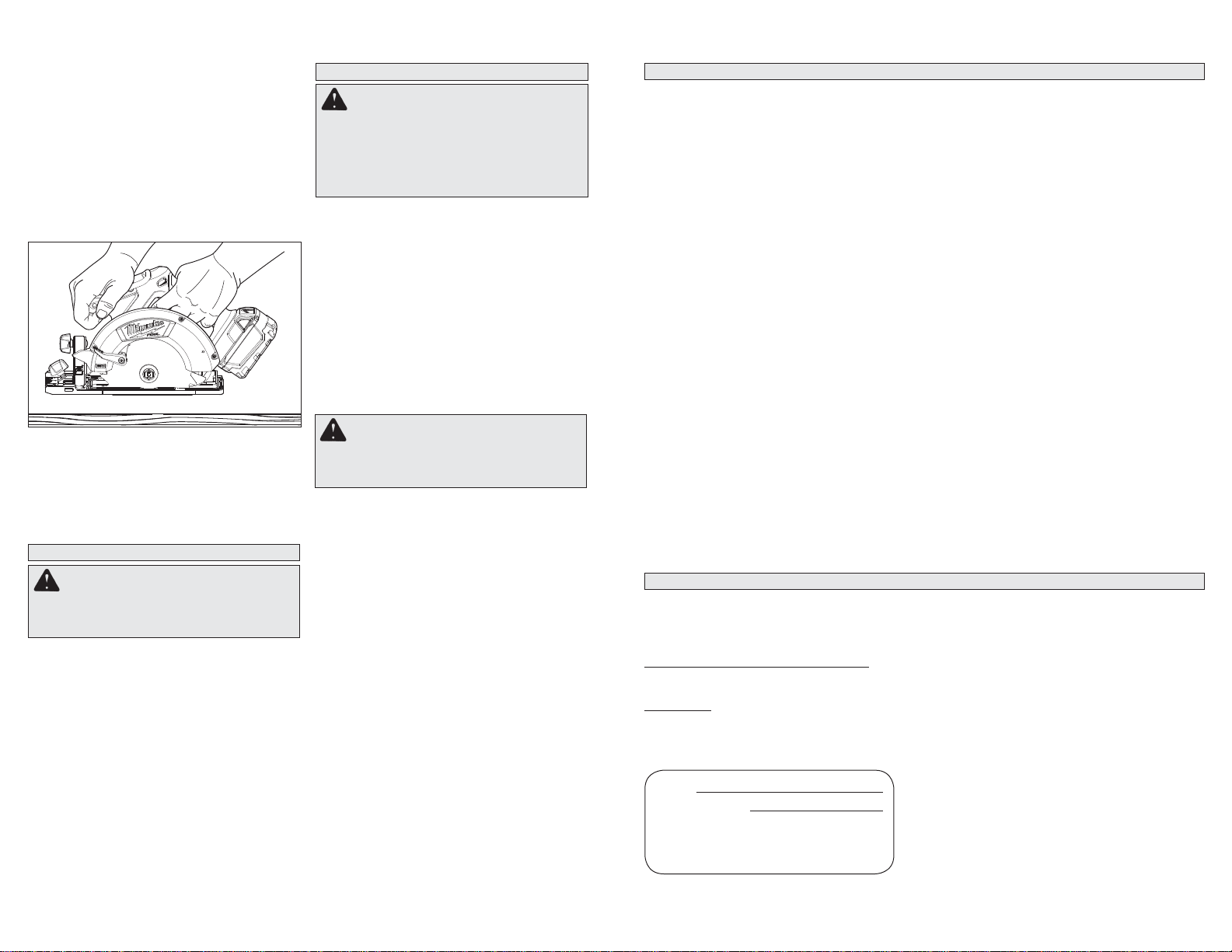
• DANGER: Keep hands away from cutting
area and the blade. Keep your second hand
on auxiliary handle, or motor housing. If both
hands are holding the saw, they cannot be cut by
the blade.
•Do not reach underneath the workpiece. The
guardcannotprotectyoufromthebladebelow the
workpiece.
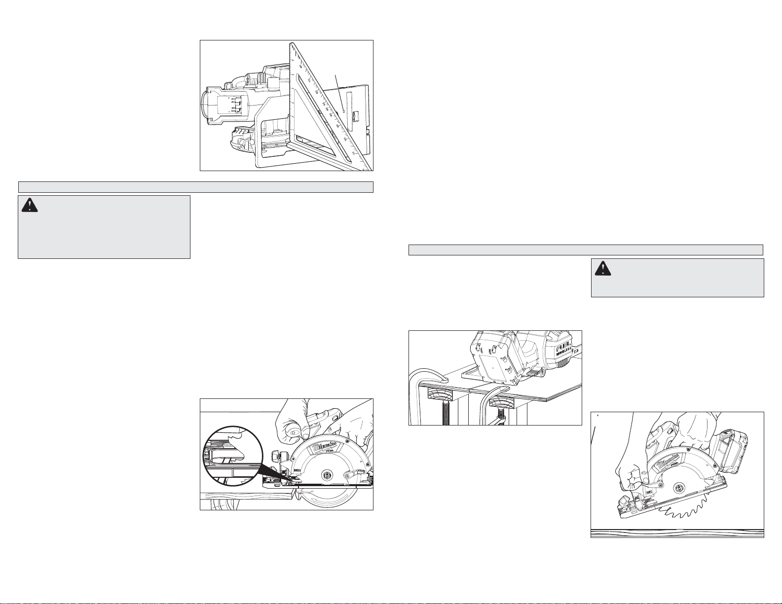
•Adjust the cutting depth to the thickness of
the workpiece. Less than a full tooth of the blade
teeth should be visible below the workpiece.
•Never hold piece being cut in your hands or
across your leg. Secure the workpiece to a
stable platform. It is important to support the
work properly to minimize body exposure, blade
binding, or loss of control.
•Hold the power tool by insulated gripping
surfaces only, when performing an operation
where the cutting tool may contact hidden
wiring. Contact with a “live” wire will also make
exposed metal parts of the power tool “live” and
could give the operator an electric shock.
•When ripping, alwaysuse a ripfence or straight
edge guide. This improves the accuracy of cut
and reduces the chance of blade binding.
•Always use blades with correct size and shape
(diamond versus round) of arbour holes.
Blades that do not match the mounting hardware
of the saw will run eccentrically, causing loss of
control.
•Never use damaged orincorrect blade washers
or bolt. Thebladewashers and bolt were specially
designed for your saw, for optimum performance
and safety of operation.
Further safety instructions for all saws
Kickback causes and related warnings
– Kickback is a sudden reaction to a pinched,
bound or misaligned saw blade, causing an un-
controlledsaw to lift upand out of theworkpiece
toward the operator;
– When the blade is pinched or bound tightly by
the kerf closing down, the blade stalls and the
motorreaction drives the unitrapidlybacktoward
the operator;
PERSONAL SAFETY
GENERAL POWER TOOL SAFETY WARNINGS
WORK AREA SAFETY
ELECTRICAL SAFETY
•Keep work area clean and well lit. Cluttered or
dark areas invite accidents.
•Do not operatepower tools in explosive atmos-
pheres, such as in the presence of flammable
liquids, gases or dust. Powertoolscreatesparks
which may ignite the dust or fumes.
•Keep children and bystanders away while
operating a power tool. Distractions can cause
you to lose control.
•Power tool plugs must match the outlet. Never
modify the plug in any way. Do not use any
adapter plugs with earthed (grounded) power
tools. Unmodified plugs and matching outlets will
reduce risk of electric shock.
•Avoid body contact with earthed or grounded
surfaces such as pipes, radiators, ranges and
refrigerators. Thereis an increased risk of electric
shock if your body is earthed or grounded.
•Do not expose powertools to rain or wet condi-
tions. Water entering a power tool will increase
the risk of electric shock.
•Do not abuse the cord. Never use the cord for
carrying, pulling or unplugging the power tool.
Keep cord away from heat, oil, sharp edges
or moving parts. Damaged or entangled cords
increase the risk of electric shock.
•When operating a power tool outdoors, use an
extension cord suitable for outdoor use. Use
of a cord suitable for outdoor use reduces the risk
of electric shock.
•If operating a power tool in a damp location
is unavoidable, use a residual current device
(RCD) protected supply. Useof an RCD reduces
the risk of electric shock.
attached to a rotating part of the power tool may
result in personal injury.
•Do not overreach. Keep proper footing and
balance at all times. This enables better control
of the power tool in unexpected situations.
•Dress properly. Do not wear loose clothing or
jewellery. Keep your hair, clothing and gloves
away from moving parts. Loose clothes, jewel-
lery or long hair can be caught in moving parts.
•If devices are provided for the connection of
dust extraction and collection facilities, ensure
these are connected and properly used. Use of
dust collection can reduce dust-related hazards.
WARNING READ ALL SAFETY WARNINGS AND ALL INSTRUCTIONS.
Failure to follow the warnings and instructions may result in electric shock, fire and/or
serious injury. Save all warnings and instructions for future reference.
The term "power tool" in the warnings refers to your mains-operated (corded) power tool or
battery-operated (cordless) power tool.
POWER TOOL USE AND CARE
•Do not force the power tool. Use the correct
power tool for your application. The correct
power tool will do the job better and safer at the
rate for which it was designed.
•Do not use thepower tool ifthe switch does not
turn it on and off. Any power tool that cannot be
controlled with the switch is dangerous and must
be repaired.
•Disconnect the plug from the power source
and/or the battery pack from the power tool
before making any adjustments, changing
accessories, or storing power tools. Such pre-
ventivesafetymeasuresreducetheriskofstarting
the power tool accidentally.
•Store idle power tools out of the reach of chil-
dren and do not allow persons unfamiliar with
the power tool or these instructions to operate
the power tool. Powertools are dangerous in the
hands of untrained users.
•Maintain power tools. Check for misalignment
or binding of moving parts, breakage of parts
and any other condition that may affect the
power tool’s operation. If damaged, have the
power tool repaired before use. Manyaccidents
are caused by poorly maintained power tools.
•Keep cutting tools sharp and clean. Properly
maintained cutting tools with sharp cutting edges
are less likely to bind and are easier to control.
•Use the power tool, accessories and tool bits
etc., in accordance with these instructions,
taking into accountthe working conditions and
the work to be performed. Use of the power tool
for operations different from those intended could
result in a hazardous situation.
•Stay alert, watch what you are doing and use
common sensewhen operatingapower tool.Do
not usea powertool whileyou are tiredor under
theinfluence of drugs, alcohol ormedication. A
moment of inattention while operating power tools
may result in serious personal injury.
•Use personal protective equipment. Always
wear eye protection. Protective equipment such
as dust mask, non-skid safety shoes, hard hat, or
hearingprotectionusedfor appropriate conditions
will reduce personal injuries.
•Prevent unintentional starting. Ensure the
switch is in the off-position before connecting
to power source and/or battery pack, picking
up or carrying the tool. Carryingpowertoolswith
yourfingerontheswitchorenergisingpowertools
that have the switch on invites accidents.
•Remove any adjusting key or wrench before
turning the power tool on. Awrench or a key left
•Recharge only with the charger specified by
the manufacturer. A charger that is suitable for
one type of battery pack may create a risk of fire
when used with another battery pack.
•Use power tools only with specifically desig-
nated battery packs. Use of any other battery
packs may create a risk of injury and fire.
BATTERY TOOL USE AND CARE
•When battery pack is not in use, keep it away
from other metal objects like paper clips,
coins, keys, nails, screws, or other small metal
objects that can make a connection from one
terminal to another. Shorting the battery termi-
nals together may cause burns or a fire.
•Under abusive conditions, liquid may be eject-
ed from the battery; avoid contact. If contact
accidentally occurs, flush with water. If liquid
contacts eyes, additionally seek medical help.
Liquidejectedfrom the battery may cause irritation
or burns. SERVICE
•Have your power tool serviced by a qualified
repair person using only identical replacement
parts. Thiswillensure that the safety of the power
tool is maintained.

45
•Lower guard should be retracted manually
only for special cuts such as “plunge cuts”
and “compound cuts.” Raise lower guard by
retracting handle and as soon as blade enters the
material, the lower guard must be released. For
all other sawing, the lower guard should operate
automatically.
•Always observe that the lower guard is cov-
ering the blade before placing saw down on
bench or floor. An unprotected, coasting blade
will cause the saw to walk backwards, cutting
whateveris in its path. Be awareofthetimeittakes
for the blade to stop after switch is released.
•Maintain labels and nameplates. These carry
important information. If unreadable or missing,
contact a MILWAUKEE service facility for a free
replacement.
•WARNING Some dust created by power sanding,
sawing, grinding, drilling, and other construction
activities contains chemicals known to cause
cancer, birth defects or other reproductive harm.
Some examples of these chemicals are:
•lead from lead-based paint
•crystallinesilicafrombricksand cement and other
masonry products, and
•arsenic and chromium from chemically-treated
lumber.
Yourriskfrom these exposures varies, depending
on how often you do this type of work. To reduce
your exposure to these chemicals: work in a well
ventilated area, and work with approved safety
equipment,such as those dustmasksthatare spe-
cially designed to filter out microscopic particles.
1. Front handle
2. Rafter hook
3. Lock-off button
4. Trigger
5. Handle
6. Lower guard lever
7. Shoe
8. Lower guard
9. Lower guard arrow
10.Blade bolt
11.Blade flange
12.Rip fence slot
13.Sight lines
14.Rip fence adjusting
knob
15.Upper guard
16.Wrench
17.Spindle lock button
18.Bevel adjusting knob
19.Bevel scale
20.Bevel pointer
21.Depth adjusting lever
Cat. No. Volts
DC No Load
RPM Blade Size Arbor Depth of Cut
At 90° Depth of Cut
at 45°
2730-20 18 5000 6-1/2" (165 mm) 5/8" 0 to 2-3/16" 0 to 1-5/8"
FUNCTIONAL DESCRIPTION
SYMBOLOGY
SPECIFICATIONS
ASSEMBLY
WARNING Recharge only with the
charger specified for the battery. For specific
charging instructions, read the operator’s
manual supplied with your charger and bat-
tery.
Inserting/Removing the Battery
To remove the battery, push in the release buttons
and pull the battery pack away from the tool.
To insert thebattery, slide the pack into the body of
the tool. Make sure it latches securely into place.
Selecting Blade
Always use sharp blades. Dull blades tend to
overload the tool and increase the chance of
KICKBACK(see"Causesand Operator Prevention
of KICKBACK"). Only use thin kerf blades with a
maximumsafeoperatingspeedgreater than the no
load RPM marked on the tool's nameplate. Read
the blade manufacturer's instructions before use.
Do not use any type of abrasive cut-off wheel or
dry diamond cutting blades.
Installing and Removing Blades
1. Remove battery pack before installing or
removing blades.
2. Place the saw on a flat surface with the blade
facing upwards. To remove the bolt from the
spindle, push in the spindle lock button. While
holdingin the spindle lockbutton,usethewrench
provided with the tool to turn the bolt clockwise.
Remove the bolt and blade flange.
3. Slide the lower guard lever up to raise the lower
guard. Remove the blade from the spindle. Al-
ways clean the spindle, upper guard and lower
guard to remove any dirt and sawdust.
NOTE:Do not removeinnerbladeflange.Larger
diameter of inner flange should face the blade.
Bolt
Outer
flange
Inner
flange
Spindle
Fig. 1
3. Raise or lower the shoe to the desired position.
Markings in 1/4" increments are located on the
inner side of the upper guard for depth setting.
For the proper depth setting, the blade should
extendnomorethan 1/8" to 1/4" below the mate-
rial being cut (Fig. 3).
4. Press down on the depth adjusting lever to
secure the shoe position.
Adjusting Bevel Angle
1. Remove battery pack.
2. To adjust the angle of the cut, hold the saw by
the handle and loosen the bevel adjusting knob
(Fig. 4).
4. To install a blade, place the blade on the spindle
with the teeth pointing in the same direction as
the arrow on the lower guard. Release the lower
guard lever.
5. Place the blade flange on the spindle and hand
tighten the bolt.
6. While holding in the spindle lock button, use the
wrench to turn the bolt counterclockwise and
tighten.
Fig. 2
WARNING Always remove battery
pack before changing or removing acces-
sories. Only use accessories specifically
recommended for this tool. Others may be
hazardous.
3. Hold the front of the shoe and rotate the saw by
the handle to the desired angle as indicated by
the markings on the bevel scale.
4. Tighten the bevel adjusting knob securely.
Fig. 4
Adjusting Depth
1. Remove battery pack.
2. To adjust the depth of the cut, hold the saw by
the handle and loosen the depth adjusting lever
by pushing it up towards the motor housing.
Volts
Direct Current
No Load Revolutions per
Minute (RPM)
Underwriters Laboratories, Inc.
United States and Canada
17
16
19
20
18
21
2
15
3
6
7
4
12 8
14
9
13 10
11
15
1/4" (6 mm)
Fig. 3

67
the workpiece as the saw is restarted.
•Support large panels to minimise the risk of
blade pinching and kickback. Largepanelstend
to sag under their own weight. Supports must be
placed under the panel on both sides, near the
line of cut and near the edge of the panel.
•Do not use dull or damaged blades. Unsharp-
ened or improperly set blades produce narrow
kerf causing excessive friction, blade binding and
kickback.
•Blade depth and bevel adjusting locking levers
must be tight and secure before making cut. If
bladeadjustmentshiftswhile cutting, it may cause
binding and kickback.
•Use extra caution when sawing into existing
walls or other blind areas. The protruding blade
may cut objects that can cause kickback.
General Operation
Always clamp the workpiece securely on a saw
horse or bench. See “APPLICATIONS” for the cor-
rectwaytosupportyourworkindifferent situations.
1. Drawacuttingline.Placethefront of the shoe on
the edge of the workpiece without making blade
contact. Hold the handle with one hand and the
front handle with the other (Fig. 6).
WARNING To reduce the risk of injury,
keep hands away from the blade and other
moving parts.Always wear safety goggles or
glasses with side shields. Use only specifi-
cally recommended accessories. Others may
be hazardous.
trigger and when the brake engages. Occasionally
thebrakemaymiss completely. If the brake misses
frequently, the saw needs servicing by an autho-
rizedMILWAUKEEservice facility.Thebrake is not
asubstitute for the guard, and youmustalwayswait
for the blade to stop completely before removing
the saw from the workpiece.
Troubleshooting
If the blade does not follow a straight line:
•Teeth are dull. This is caused by hitting a hard
object such as a nail or stone, dulling teeth on
one side. The blade tends to cut to the side with
the sharpest teeth.
•Shoe is out of line or bent
•Blade is bent
•Rip fence or guide is not being used
If the blade binds, smokes or turns blue from
friction:
•Blade is dull
•Blade is on backwards
•Blade is bent
•Blade is dirty
•Workpiece is not properly supported
•Incorrect blade is being used
2. Lineup the sight linewith your cutting line. Posi-
tion your arms and body to resist KICKBACK.
3. To start the saw, push the lock-off button down
whilepullingthetrigger.Allow the motor to reach
full speed before beginning cut.
Cutting Large Panels
Large panels and long boards sag or bend if they
are not correctly supported. If you attempt to
cut without leveling and properly supporting the
workpiece, the blade will tend to bind, causing
KICKBACK.
Support large panels. Be sure to set the depth of
the cut so that you only cut through the workpiece,
not through the supports.
Fig. 7
Fig. 6
OPERATION
APPLICATIONS
Cross-Cutting Wood
Cross-cuttingiscuttingacross the grain. Select the
proper blade for your job.Advance the saw slowly
to avoid splintering the wood.
Ripping Wood
Ripping is cutting lengthwise with the grain. Select
the proper blade for your job. Use a rip fence for
rips 4" wide or less. To install the rip fence, slide
the bar through the rip fence slot in either side of
the shoe. The width of the cut is the distance from
the inside of the blade to the inside edge of the rip
fence. Adjust the rip fence for the desired width,
and lock the setting by tightening the rip fence
adjusting knob.
When ripping widths greater than 4", clamp or tack
1" lumber to workpiece and use the inside edge of
the shoe as a guide.
Plunge Cutting
Plunge cuts are made in the middle of the work-
piecewhen it can notbe cut from anedge. Werec-
ommend using a Sawzall®reciprocating saw or jig
saw for this type of cut. However, if you must use a
circularsawtomake a plunge cut, USE EXTREME
CAUTION. To maintain control of the saw during
plunge cutting, keep both hands on the saw.
1. Beginning at a corner, line up the sight line with
yourcuttingline.Tiltthesawforward,firmlyfixing
the front of the shoe on the workpiece (Fig. 8).
The blade should be just above cutting line, but
not touching it. Raise the lower guard using the
lower guard lever.
WARNING To reduce the risk of elec-
tric shock, check work area for hidden pipes
and wires before making plunge cuts.
Bevel
adjustment
screw
Fig. 5
Adjusting the Blade to Shoe
The shoe has been adjusted at the factory to a 90°
setting. Inspect the saw regularly to make sure the
blade is 90° to the shoe.
1. Remove battery pack.
2. Set the bevel pointer to zero.
3. To make sure the blade is 90° to the shoe, place
saw on the blade side and retract lower guard.
Place a square against the blade and shoe to
inspect the degree setting (Fig. 5).
4. To adjust the degree setting, loosen the bevel
adjustingknob.Turnthe bevel adjustment screw
in or out until the blade is at a 90° angle with the
shoe.
5. Tighten the bevel adjusting knob securely.
Causesand Operator Prevention of KICKBACK:
KICKBACK is a sudden reaction to a pinched,
bound or misaligned saw blade, causing an un-
controlled saw to lift up and out of the workpiece
toward the operator.
When the blade is pinched or bound tightly by the
kerf closing down, the blade stalls and the motor
reaction drives the unit rapidly back toward the
operator.
If the blade becomes twisted or misaligned in
the cut, the teeth at the back edge of the blade
can dig into the top surface of the wood causing
the blade to climb out of the kerf and jump back
toward operator.
KICKBACK is the result of saw misuse and/or
incorrect operating procedures or conditions and
can be avoided by taking proper precautions as
given below:
•Maintain a firm grip with both hands on the
saw and position your arms to resist kickback
forces. Position your body to either side of the
blade, but not in line with the blade. Kickback
could cause the saw to jump backwards, but kick-
back forces can be controlled by the operator, if
proper precautions are taken.
•When blade is binding, or when interrupting
a cut for any reason, release the trigger and
hold the saw motionless in the material until
the blade comes to a complete stop. Never
attempt to remove the saw from the work or
pull the saw backward while the blade is in
motion or kickback may occur. Investigate and
take corrective actions to eliminate the cause of
blade binding.
•When restarting a saw in the workpiece, centre
the saw blade in the kerf and check that saw
teeth are not engaged into the material. If saw
blade is binding, it may walk up or kickback from
4. While cutting, keep the shoe flat against the
workpiece and maintain a firm grip. Do not force
the saw through the workpiece. Forcing a saw
can cause KICKBACK.
5. If making a partial cut, restarting in mid-cut or
correcting direction, allow the blade to come to
a complete stop. To resume cutting, center the
blade in the kerf, back the saw away from cut-
ting edge a few inches, push the lock-off button
down while pulling the trigger and re-enter the
cut slowly.
6. If the saw binds and stalls, maintain a firm grip
and release the trigger immediately. Hold the
saw motionless in the workpiece until the blade
comes to a complete stop.
7. After finishing a cut, be sure the lower guard
closes and the blade comes to a complete stop
before setting the saw down.
Electric Brake
The electric brake engages when the trigger is
released, causing the blade to stop and allowing
you to proceed with your work. Generally, the saw
blade stops within two seconds. However, there
may be a delay between the time you release the
Fig. 8

89
Fig. 9
ACCESSORIES
For a complete listing of accessories refer to your
MILWAUKEE Electric Tool catalog or go online
to www.milwaukeetool.com. To obtain a catalog,
contact your local distributor or service center.
WARNINGAlways removebatterypack
before changing or removing accessories.
Onlyuseaccessoriesspecificallyrecommend-
ed for this tool. Others may be hazardous.
Maintaining Tool
Keep your tool, battery pack and charger in good
repairbyadoptingaregularmaintenanceprogram.
After six months to one year, depending on use,
return the tool, battery pack and charger to A
MILWAUKEE service facility for:
•Lubrication
•Mechanical inspection and cleaning (gears, spin-
dles, bearings, housing, etc.)
•Electricalinspection(batterypack,charger,motor)
•Testing to assure proper mechanical and electrical
operation
If the tool does not start or operate at full power
withafully charged battery pack, clean the contacts
on the battery pack. If the tool still does not work
properly, return the tool, charger and battery pack,
to a MILWAUKEE service facility for repairs.
MAINTENANCE
Cleaning
Cleandust and debris from charger andtoolvents.
Keep tool handles clean, dry and free of oil or
grease. Use only mild soap and a damp cloth to
cleanthetool,batterypackandchargersincecertain
cleaningagents and solvents areharmfultoplastics
and other insulated parts. Some of these include
gasoline, turpentine, lacquer thinner, paint thinner,
chlorinatedcleaning solvents, ammonia andhouse-
hold detergents containing ammonia. Never use
flammable or combustible solvents around tools.
Repairs
For repairs, return the tool, battery pack and
charger to the nearest service center.
WARNING To reduce the risk of per-
sonal injury and damage, never immerse your
tool, battery pack or charger in liquid or allow
a liquid to flow inside them.
WARNING To reduce the risk of injury,
always unplug the charger and remove the
battery pack from the charger or tool before
performing any maintenance. Never disas-
semble the tool, battery pack or charger.
Contact a MILWAUKEE service facility for
ALL repairs.
TECHTRONIC INDUSTRIES' warranty is for 5 year since the original purchase date.
This warranty card covers any defect in material and workmanship on this Power Tool.
To make this warranty valid, present this warranty card, sealed/stamped by the distributor or store where you pur-
chased the product, to theAuthorized Service Center (ASC). Or, if this card has not been sealed/stamped, present the
original proof of purchase to the ASC.
Call toll-free 1 800 832 1949 to find the nearest ASC, for service, parts, accessories or components.
Procedure to make this warranty valid
Take the product to the ASC, along with the warranty card sealed/stamped by the distributor or store where you pur-
chased the product, and there any faulty piece or component will be replaced without cost for you. We will cover all
freight costs relative with this warranty process.
Exceptions
This warranty is not valid in the following situations:
a) When the product is used in a different manners from the end-user guide or instruction manual.
b) When the conditions of use are not normal.
c) When the product was modified or repaired by people not authorized by TECHTRONIC INDUSTRIES.
Note: If cord set is damaged, it should be replaced by an Authorized Service Center to avoid electric risks.
SERVICE AND ATTENTION CENTER
Av Presidente Mazarik 29 Piso 7, 11570 Chapultepec Morales
Miguel Hidalgo, Distrito Federal, Mexico
Ph. 52 55 4160-3547
IMPORTEDAND COMMERCIALIZED BY:
TECHTRONIC INDUSTRIES MEXICO, .S.A. DE C.V.
Av Presidente Mazarik 29 Piso 7, 11570 Chapultepec Morales
Miguel Hidalgo, Distrito Federal, Mexico
LIMITED WARRANTY - USA AND CANADA
LIMITED WARRANTY - MEXICO, CENTRAL AMERICA AND CARIBBEAN
Model:
Date of Purchase:
Distributor or Store Stamp:
Every MILWAUKEE power tool (including cordless product – tool, battery pack(s) - see separate & distinct
CORDLESS BATTERY PACK LIMITED WARRANTY statements & battery charger and Work Lights*) is war-
ranted to the original purchaser only to be free from defects in material and workmanship. Subject to certain
exceptions, MILWAUKEE will repair or replace any part on an electric power tool which, after examination, is
determined by MILWAUKEE to be defective in material or workmanship for a period of five (5) years* after the
date of purchase unless otherwise noted. Return of the power tool to a MILWAUKEE factory Service Center
location or MILWAUKEE Authorized Service Station, freight prepaid and insured, is required. A copy of the
proof of purchase should be included with the return product. This warranty does not apply to damage that
MILWAUKEE determines to be from repairs made or attempted by anyone other than MILWAUKEE authorized
personnel, misuse, alterations, abuse, normal wear and tear, lack of maintenance, or accidents.
*The warranty period for, Job Site Radios, M12™ Power Port, M18™ Power Source, and TradeTitan™ Indus-
trial Work Carts is one (1) year from the date of purchase. The warranty period for a LED Work Light and LED
Upgrade Bulb is a limited LIFETIME warranty to the original purchaser only, if during normal use the LED bulb
fails the Work Light or Upgrade Bulb will be replaced free of charge.
*This warranty does not cover Air Nailers & Stapler, Airless Paint Sprayer, Cordless Battery Packs, Gasoline
Driven Portable Power Generators, Hand Tools, Hoist – Electric, Lever & Hand Chain, M12™ Heated Jackets,
Reconditioned product and Test & Measurement products. There are separate and distinct warranties avail-
able for these products.
Warranty Registration is not necessary to obtain the applicable warranty on a MILWAUKEE power tool product.
The manufacturing date of the product will be used to determine the warranty period if no proof of purchase is
provided at the time warranty service is requested.
ACCEPTANCE OF THE EXCLUSIVE REPAIR AND REPLACEMENT REMEDIES DESCRIBED HEREIN IS A
CONDITIONOFTHECONTRACTFORTHEPURCHASEOF EVERYMILWAUKEEPRODUCT.IFYOUDONOT
AGREE TO THIS CONDITION, YOU SHOULD NOT PURCHASE THE PRODUCT. IN NO EVENT SHALL MIL-
WAUKEEBE LIABLEFORANYINCIDENTAL,SPECIAL,CONSEQUENTIALOR PUNITIVEDAMAGES,ORFOR
ANY COSTS,ATTORNEY FEES, EXPENSES, LOSSES OR DELAYSALLEGED TO BEASACONSEQUENCE
OFANYDAMAGETO,FAILUREOF,OR DEFECTINANYPRODUCTINCLUDING,BUTNOTLIMITEDTO,ANY
CLAIMSFOR LOSS OF PROFITS. SOMESTATES DONOTALLOW THE EXCLUSION OR LIMITATIONOF IN-
CIDENTALOR CONSEQUENTIALDAMAGES,SOTHEABOVE LIMITATION OREXCLUSIONMAYNOTAPPLY
TOYOU.THISWARRANTYIS EXCLUSIVEANDIN LIEUOFALLOTHER EXPRESSWARRANTIES,WRITTEN
OR ORAL. TO THE EXTENT PERMITTED BY LAW, MILWAUKEE DISCLAIMS ANY IMPLIED WARRANTIES,
INCLUDING WITHOUT LIMITATIONANY IMPLIED WARRANTYOF MERCHANTABILITY OR FITNESS FORA
PARTICULARUSEOR PURPOSE;TOTHEEXTENTSUCH DISCLAIMERISNOTPERMITTED BYLAW, SUCH
IMPLIED WARRANTIESARE LIMITED TO THE DURATION OFTHEAPPLICABLE EXPRESS WARRANTYAS
DESCRIBEDABOVE.SOMESTATESDO NOTALLOWLIMITATIONSONHOWLONGANIMPLIED WARRANTY
LASTS, SO THE ABOVE LIMITATION MAY NOT APPLY TO YOU, THIS WARRANTY GIVES YOU SPECIFIC
LEGAL RIGHTS, AND YOU MAY ALSO HAVE OTHER RIGHTS WHICH VARY FROM STATE TO STATE.
This warranty applies to product sold in the U.S.A. and Canada only.
Please consult the ‘Service Center Search’ in the Parts & Service section of MILWAUKEE’s website www.mil-
waukeetool.com or call 1.800.SAWDUST (1.800.729.3878) to locate your nearest service facility for warranty
and non-warranty service on a Milwaukee electric power tool.
2. To start the saw, push the lock-off button down
whilepullingthetrigger.Allow the motor to reach
full speed before beginning cut. Using the front
of the shoe as a hinge point, gradually lower the
backendofthe saw into the workpiece. Release
thelowerguardleverandgraspthefronthandle.
3. When the shoe rests flat against workpiece,
advance the saw to the far corner (Fig. 9). Re-
lease the trigger and allow the blade to come to
a complete stop before removing it from work-
piece. Repeat the above steps for each side of
the opening. Use a Sawzall® reciprocating saw,
jig saw or small hand saw to finish the corners
if they are not completely cut through.
Other manuals for 2730-20
1
Table of contents
Languages:
Other Milwaukee Circular Saw manuals