manuals.online logo
Brands
  1. Home
  2. •
  3. Brands
  4. •
  5. Milwaukee
  6. •
  7. Drill
  8. •
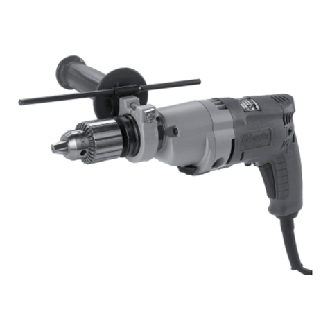
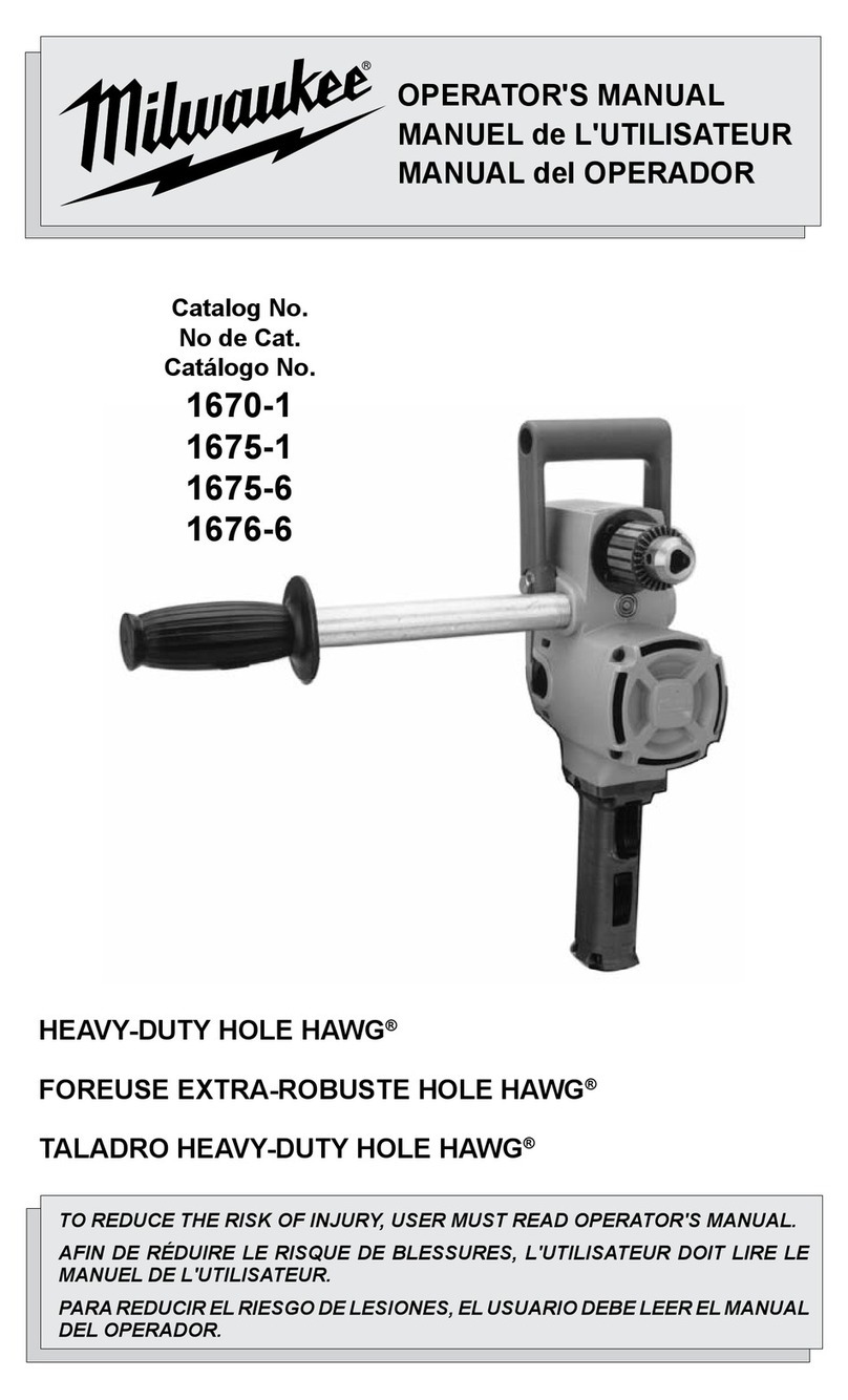
  9. Milwaukee 1670-1 User manual

Milwaukee 1670-1 User manual

Other manuals for 1670-1

2

This manual suits for next models

3

Other Milwaukee Drill manuals

Milwaukee V 28 PD User manual

Milwaukee

Milwaukee V 28 PD User manual

Milwaukee PD2-18 User manual

Milwaukee

Milwaukee PD2-18 User manual

Milwaukee 2902-20 User manual

Milwaukee

Milwaukee 2902-20 User manual

Milwaukee 1854-1 User manual

Milwaukee

Milwaukee 1854-1 User manual

Milwaukee PLH 30 XE User manual

Milwaukee

Milwaukee PLH 30 XE User manual

Milwaukee PLH 30 XE Operation instructions

Milwaukee

Milwaukee PLH 30 XE Operation instructions

Milwaukee M12 2415-20 User manual

Milwaukee

Milwaukee M12 2415-20 User manual

Milwaukee M18 FPD User manual

Milwaukee

Milwaukee M18 FPD User manual

Milwaukee PD2-18 User manual

Milwaukee

Milwaukee PD2-18 User manual

Milwaukee M12 BDD-402C User manual

Milwaukee

Milwaukee M12 BDD-402C User manual

Milwaukee M4 D User manual

Milwaukee

Milwaukee M4 D User manual

Milwaukee C18 RAD-0 User manual

Milwaukee

Milwaukee C18 RAD-0 User manual

Milwaukee HD28 PD/0 User manual

Milwaukee

Milwaukee HD28 PD/0 User manual

Milwaukee M18 CBLPD-422 User manual

Milwaukee

Milwaukee M18 CBLPD-422 User manual

Milwaukee 162-1001 Guide

Milwaukee

Milwaukee 162-1001 Guide

Milwaukee 1001-1 User manual

Milwaukee

Milwaukee 1001-1 User manual

Milwaukee K 540 S User manual

Milwaukee

Milwaukee K 540 S User manual

Milwaukee 4000442205 User manual

Milwaukee

Milwaukee 4000442205 User manual

Milwaukee R-600 Guide

Milwaukee

Milwaukee R-600 Guide

Milwaukee MDP 41 User manual

Milwaukee

Milwaukee MDP 41 User manual

Milwaukee PLD 12 X User manual

Milwaukee

Milwaukee PLD 12 X User manual

Milwaukee 2410-059 User manual

Milwaukee

Milwaukee 2410-059 User manual

Milwaukee V 18 H User manual

Milwaukee

Milwaukee V 18 H User manual

Milwaukee PD 705 User manual

Milwaukee

Milwaukee PD 705 User manual

Popular Drill manuals by other brands

Stanley FatMax FME140 Original instructions

Stanley

Stanley FatMax FME140 Original instructions

Black & Decker MATRIX BDCDMT120C instruction manual

Black & Decker

Black & Decker MATRIX BDCDMT120C instruction manual

DeWalt D25134 manual

DeWalt

DeWalt D25134 manual

Skil 2431 Original instructions

Skil

Skil 2431 Original instructions

Bort 93728410 user manual

Bort

Bort 93728410 user manual

GreenWorks DDG407 Operator's manual

GreenWorks

GreenWorks DDG407 Operator's manual

Panasonic EY7460 - DRILL DRIVER 21.6V operating instructions

Panasonic

Panasonic EY7460 - DRILL DRIVER 21.6V operating instructions

Mueller E-5 operating instructions

Mueller

Mueller E-5 operating instructions

Bosch GSB Professional 18-2 RE Original instructions

Bosch

Bosch GSB Professional 18-2 RE Original instructions

Clarke CON18LI Operation & maintenance instructions

Clarke

Clarke CON18LI Operation & maintenance instructions

Makita 8280D technical information

Makita

Makita 8280D technical information

Stanley SCH20 user manual

Stanley

Stanley SCH20 user manual

Makita BDF456 instruction manual

Makita

Makita BDF456 instruction manual

Makita LXFD01 instruction manual

Makita

Makita LXFD01 instruction manual

Black & Decker LDX220 instruction manual

Black & Decker

Black & Decker LDX220 instruction manual

GMC HD1400K instruction manual

GMC

GMC HD1400K instruction manual

POWERBOR PB1000E owner's manual

POWERBOR

POWERBOR PB1000E owner's manual

Festool T18+3 instructions

Festool

Festool T18+3 instructions

manuals.online logo
manuals.online logoBrands
  • About & Mission
  • Contact us
  • Privacy Policy
  • Terms and Conditions

Copyright 2025 Manuals.Online. All Rights Reserved.

Installing Bits into Keyed Chucks (Fig. 1)
1. Unplug tool.
2. Open the chuck jaws
wide enough to insert the
bit. Be sure the bit shank
and chuck jaws are clean.
Dirt particles may prevent
the bit from lining up prop-
erly.
3. Insert the bit into the chuck. Center the bit in the chuck jaws
and lift it about 1/16” off of the bottom. Then, tighten the
chuck jaws by hand to align the bit.
4. Place the chuck key in each of the three holes in the chuck,
turning it clockwise as shown. Tighten securely.
5. To remove the bit, insert the chuck key into one of the
holes in the chuck and turn it counterclockwise.
Bit Selection
 Use sharp bits. Sharp bits are less likely to bind when drilling.
 Use the proper bit for the job. There are many types of bits
designed for specific purposes. Check the informa
tion on the bit’s packaging for proper usage.
 Do not use bits larger than the rated capacity of the drill.
Gear damage or motor overload may result. See
Specifications on page 4.
Removing and replacing
Quik-Lok®Cords (Fig. 2)
MILWAUKEE’S exclusive
Quik-Lok® Cords provide
instant field replacement or
substitution.
1. Unplug tool from electri-
cal outlet.
2. To remove the Quik-Lok®
Cord, turn the cord nut 1 /4
turn to the left and pull it out.
3. To replace the Quik-Lok Cord, align the connector keyways
and push the connector in as far as it will go. Turn the cord nut
1/4 to the right to lock. (See Fig. 2)
Pipe Handle (Fig. 3)
The pipe handle may be used on either side of the tool. Thread
pipe handle into one of the threaded holes in the motor hous-
ing. (See Fig. 3)
Spade Handle (Fig. 4)
The spade handle can be attached to the tool
in three positions as shown in Fig. 4.
Remove the hex head screws which secure
the handle. Remove the handle and move it
to the desired position. To mount the handle
in position C, it is necessary to reverse the
mounting holes by turning the handle
around.
Milwaukee Tool
Heavy-Duty Hole Hawg®
Model Numbers: 1670-1, 1675-1, 1678-20, 1679-20
Operating Instructions
Page 1
RenTrain INC RenTrain INC
To reduce the risk of injury, always unplug tool
before attaching or removing accessories. Use
only specifically recommended accessories.
Others may be hazardous.
WARNING!
ASSEMBLY
Fig. 1
Fig. 2
Fig. 3
Fig. 4 A
B
C
(Continued on next page)
Bit binding (Fig. 5)
Bit binding (Contined)
If the bit binds, the drill will suddenly react in the opposite
direction of the rotation of the bit. Figure 5 shows the path of
reaction, (B) if the drill bit binds while being driven in for-
ward (A). The operator should reduce the chances of a sud-
den reaction by following the instructions listed below.
The operator should also prepare for a sudden reaction by
holding securely using the pipe handle or bracing against a
solid fixed object.
See bracing instructions are on page 3.
To reduce the chance of bit binding
•Use sharp bits. Sharp bits are less likely to bind
when drilling.
•Use the proper bit for the job. There are many types
of bits designed for specific purposes.
•Use the proper speed for the size bit. Larger bits
should be run at the lower speed (specifications on
page 3). Driving larger bits at high speeds will
increase the chance of the bit binding and increase
the chance of reaction.
•Avoid drilling warped, wet, knotty, and or pitchy
material if possible.
•Avoid drilling in material that you suspect contains
hidden nails or other things that may cause the bit to
bind.
The direction of reaction is always opposite of the direction of
bit rotation.
Reaction is even more likely to occur when enlarging already
existing holes and at the point when the bit breaks through the
other side of the material.
(Continued on next page)
Operating Instructions (continued)
Page 2
RenTrain INC RenTrain INC
To reduce the risk of personal injury when
drilling, hold tool by insulated gripping
surfaces when performing an operation where
the cutting tool may contact hidden wiring or
its own cord. Contact with a “live” wire will
make exposed metal parts of the tool “live”
and shock the operator.
WARNING!
When drilling with a single speed drill or in HI
with a two-speed drill, always hold the drill
securely using the pipe handle, or brace the
drill against a solid fixed object in preparation
for a sudden reaction. When drilling in LO with
a two-speed drill, always brace the drill against
a solid fixed object in preparation for a sudden
reaction.
When drilling, never use your body to brace
drill.
Never put your hands (or other body parts)
between the part of the drill being braced and
the object it is being braced against. Hands (or
other body parts) that are in the path of the
reaction can be pinched, crushed and broken.
See Bracing Instructions, Page 3 Figures 6 & 7.
WARNING!
OPERATION
B
A
When drilling in forward, the bit will rotate in a clockwise
direction. If the bit binds in the hole, the bit will come to a
sudden stop and drill will suddenly react in a counterclock-
wise direction.
Figure 6 shows two examples of a Hole Hawg® properly
braced for forward rotation.
A Forward (clockwise) rotation
B. Reaction
C. Brace drill with pipe handle here
D. Brace drill with motor housing here
If the bit binds, the pipe handle or the motor housing braced
against the stud will hold the drill in position.
When drilling in reverse, the bit will rotate in a counterclock-
wise direction. If the bit binds in the hole, the bit will come
to a sudden stop and the drill will suddenly react in a clock-
wise direction.
Figure 7 shows two examples of the Hole Hawg® properly
braced for reverse rotation.
A Reverse (counterclockwise) rotation
B. Reaction
C. Brace drill with pipe handle here
D. Brace drill with motor housing here
If the bit binds, the pipe handle or the motor housing braced
against the stud will hold the drill in position.
Operating Instructions (continued)
Page 3
RenTrain INC RenTrain INC
B
B
B
B
C
C
A
AA
A
DD
Fig. 7
Fig. 6
Shifting Speeds (Fig. 8)
Catalog Nos. 1675-1, 1678-20 and 1679-20 have a gear shift
lever on the right side of the gear case. The arrow in Fig. 8
indicates shift lever rotation.
The high setting (1200 RPM HI) is the low torque setting and
is designed for driving Selfeed bits 1-3/8” in diameter and
smaller.
The low setting (300 RPM LO) is the high torque setting and
is designed for driving Selfeed bits 1-1/2” in diameter and larg-
er. See specifications, page 4.
Always turn off the switch and shift while the tool is coasting
to a stop. Never shift the drill while it is moving at full speed,
when it is under load, or when it is stopped.
Speed Control Dial (Fig. 9)
Catalog number 1678-20 is fur-
nished with a Speed Control
Dial (Fig. 9A) to provide elec-
tronic speed control in addition
to the gearing speed change
described above. (The trigger
does not control the speed - it
only turns the tool on and off).
The dial is located on the rear of
the handle. The dial has posi-
tions numbered 1-8. Position 8
provides full speed at no load.
Position 1 provides approxi-
mately 25% of the full no load
speed. Reduced speed can be
useful for starting bits and obtaining the optimum speed
for a given bit size. Do not adjust the speed while drilling.
This tool is furnished with Electronic Feedback to provide
a more constant speed under load.
Reversing (Fig 10.)
A reversing switch is located below the trigger switch (A),
above for Cat. No. 1678-20 (B), for removal of bits from holes.
Permit the motor to come to a complete stop before reversing.
Reversing the tool with the gears in motion may cause severe
damage. When removing selfeed bits from partially drilled
holes, a flick of the trigger switch will free the threaded pilot
screw. When the threads are loose, lift the bit from the work-
piece with the motor stopped.
Drilling
Before drilling, clamp material down securely. A poorly secured
piece of material may result in personal injury or inaccurate
drilling. When drilling light gauge metal or wood, use a wooden
block to back up material to prevent damage to workpiece.
Center the hole to be drilled with a center punch to give the bit a
start and to prevent it from “walking.” Lubricate the drill bit with
cutting oil when drilling iron or steel. Use a coolant when drilling
nonferrous metals such as copper, brass or aluminum.
To start a selfeed bit, run the threaded feed screw into the work
by flicking the trigger switch, permitting the bit to coast until the
teeth contact the work surface. Align the bit properly before pro-
ceeding. This will reduce cocking and jamming when starting. To
reduce jamming on breakthrough, decrease the drilling pressure
when the feed screw point breaks through the workpiece.Proceed
with steady, even pressure.
Operating Instructions (continued)
Page 4
RenTrain INC RenTrain INC
Fig. 8
Fig. 9
Fig. 10
A
B
A
Catalog
Number
Volts
AC
Only
SPECIFICATIONS
With
Selfeed
Bit
Speed No Load
RPM
With
Auger
Bit
With Ship
Auger Bit
Capacity
Wood
Steel
1670-1 120 - 900 7/16” 1-1/2” 1-1/2” 2-9/16”
1675-1 120
High
Low
1200
300
5/16”
1/2”
1-1/8”
1-1/2”
1-1/4”
1-1/2”
1-3/8”
4-5/8”
1678-20 120
High
Low
300-1200
75-300
5/16”
1/2”
1-1/8”
1-1/2”
1-1/4”
1-1/2”
1-3/8”
4-5/8”
1679-20 120
High
Low
1200
300
5/16”
1/2”
1-1/8”
1-1/2”
1-1/4”
1-1/2”
1-3/8”
4-5/8”
With
Twist
Bit