manuals.online logo
Brands
  1. Home
  2. •
  3. Brands
  4. •
  5. Milwaukee
  6. •
  7. Drill
  8. •
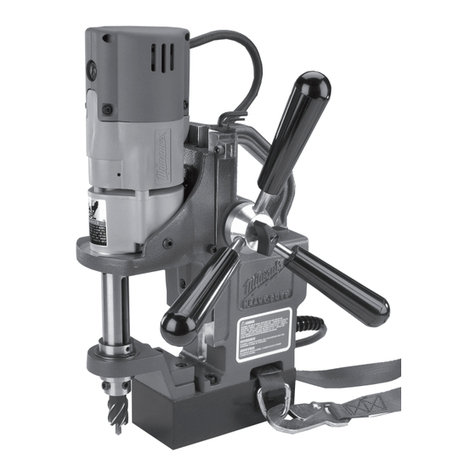
  9. Milwaukee Dymodrill Guide

Milwaukee Dymodrill Guide

This manual suits for next models

1

Other Milwaukee Drill manuals

Milwaukee PH 28 X User manual

Milwaukee

Milwaukee PH 28 X User manual

Milwaukee M12 CDD User manual

Milwaukee

Milwaukee M12 CDD User manual

Milwaukee HDE 6 RQ User manual

Milwaukee

Milwaukee HDE 6 RQ User manual

Milwaukee 2601-20 User manual

Milwaukee

Milwaukee 2601-20 User manual

Milwaukee M18 FUEL ONE-KEY ONEPD3 User manual

Milwaukee

Milwaukee M18 FUEL ONE-KEY ONEPD3 User manual

Milwaukee M18 CPD User manual

Milwaukee

Milwaukee M18 CPD User manual

Milwaukee MDP 41 User manual

Milwaukee

Milwaukee MDP 41 User manual

Milwaukee K 540 S User manual

Milwaukee

Milwaukee K 540 S User manual

Milwaukee 0100-20 User manual

Milwaukee

Milwaukee 0100-20 User manual

Milwaukee 1000-1 Guide

Milwaukee

Milwaukee 1000-1 Guide

Milwaukee R-600 Guide

Milwaukee

Milwaukee R-600 Guide

Milwaukee M18 2801-20 User manual

Milwaukee

Milwaukee M18 2801-20 User manual

Milwaukee M18 BLDD User manual

Milwaukee

Milwaukee M18 BLDD User manual

Milwaukee M18 User manual

Milwaukee

Milwaukee M18 User manual

Milwaukee PD2E 22 RS User manual

Milwaukee

Milwaukee PD2E 22 RS User manual

Milwaukee 5371-20 User manual

Milwaukee

Milwaukee 5371-20 User manual

Milwaukee 0613-20 User manual

Milwaukee

Milwaukee 0613-20 User manual

Milwaukee HEAVY DUTY M18 BLHACD26 User manual

Milwaukee

Milwaukee HEAVY DUTY M18 BLHACD26 User manual

Milwaukee 58-01-0010 User manual

Milwaukee

Milwaukee 58-01-0010 User manual

Milwaukee PFH24 E User manual

Milwaukee

Milwaukee PFH24 E User manual

Milwaukee PD2E 24 RST User manual

Milwaukee

Milwaukee PD2E 24 RST User manual

Milwaukee M12 FPD User manual

Milwaukee

Milwaukee M12 FPD User manual

Milwaukee M18 FUEL FMDP User manual

Milwaukee

Milwaukee M18 FUEL FMDP User manual

Milwaukee M18 FUEL 2804-20 User manual

Milwaukee

Milwaukee M18 FUEL 2804-20 User manual

Popular Drill manuals by other brands

Stanley FatMax FME140 Original instructions

Stanley

Stanley FatMax FME140 Original instructions

Black & Decker MATRIX BDCDMT120C instruction manual

Black & Decker

Black & Decker MATRIX BDCDMT120C instruction manual

DeWalt D25134 manual

DeWalt

DeWalt D25134 manual

Skil 2431 Original instructions

Skil

Skil 2431 Original instructions

Bort 93728410 user manual

Bort

Bort 93728410 user manual

GreenWorks DDG407 Operator's manual

GreenWorks

GreenWorks DDG407 Operator's manual

Panasonic EY7460 - DRILL DRIVER 21.6V operating instructions

Panasonic

Panasonic EY7460 - DRILL DRIVER 21.6V operating instructions

Mueller E-5 operating instructions

Mueller

Mueller E-5 operating instructions

Bosch GSB Professional 18-2 RE Original instructions

Bosch

Bosch GSB Professional 18-2 RE Original instructions

Clarke CON18LI Operation & maintenance instructions

Clarke

Clarke CON18LI Operation & maintenance instructions

Makita 8280D technical information

Makita

Makita 8280D technical information

Stanley SCH20 user manual

Stanley

Stanley SCH20 user manual

Makita BDF456 instruction manual

Makita

Makita BDF456 instruction manual

Makita LXFD01 instruction manual

Makita

Makita LXFD01 instruction manual

Black & Decker LDX220 instruction manual

Black & Decker

Black & Decker LDX220 instruction manual

GMC HD1400K instruction manual

GMC

GMC HD1400K instruction manual

POWERBOR PB1000E owner's manual

POWERBOR

POWERBOR PB1000E owner's manual

Festool T18+3 instructions

Festool

Festool T18+3 instructions

manuals.online logo
manuals.online logoBrands
  • About & Mission
  • Contact us
  • Privacy Policy
  • Terms and Conditions

Copyright 2025 Manuals.Online. All Rights Reserved.

1 42-90-0210 Water Hose Fitting (1)
2 45-80-0060 Shut Off Valve (1)
3 06-57-1050 Retaining Nut (1)
4 45-88-1140 Thrust Washer (2)
5 43-06-0160 Clutch Disc-Outer (3)
6 43-06-0150 Clutch Disc-Inner (5)
7 43-76-0051 Water Swivel Hsg. w/ 06-83-2430 Scr. (1)
8 40-50-2150 Disc Spring (4)
9 45-06-0635 Seal (2)
10 45-88-8565 Washer (Bag of 2) (1)
13 38-50-6020 Spindle (1)
16 34-80-3800 Retaining Ring (1)
17 02-20-2515 Ball Bearing (1)
18 06-82-9202 1/4-20 x 4-1/4" Taptite T-30 (4)
19 28-14-1870 Gear Case Assy.(Inc. 06-65-1535 Pin) (1)
20 45-36-1520 Spindle Spacer (1)
21 32-75-3440 Spindle Gear (1)
22 02-50-4830 Needle Bearing (1)
23 02-04-1205 Ball Bearing (4)
24 36-66-3751 Pinion Shaft Assy. (1)
25 06-42-1600 Woodruff Key (1)
26 32-40-1581 Intermediate Gear (1)
27 40-50-6300 Shifting Spring (2)
28 44-70-0100 Shifting Plunger (2)
29 32-60-2011 Pinion Gear (1)
30 45-88-0520 Thrust Bearing Washer (1)
31 02-80-1800 Thrust Bearing (1)
32 32-10-0061 Clutch Gear Assembly (1)
33 06-42-2000 Woodruff Key (1)
34 36-14-0061 Clutch Shaft (1)
35 45-88-0530 Thrust Bearing Washer (1)
36 02-80-5000 Thrust Bearing (1)
37 32-10-0051 Clutch Gear Assembly (1)
38 45-88-0510 Thrust Bearing Washer (2)
39 02-80-1200 Thrust Bearing (1)
40 45-98-0090 Shifting Yoke (1)
41 14-13-0210 Diaphragm Assy.(Inc. 06-65-1155 Pin) (1)
42 30-15-0272 Shift Cam (1)
43 43-44-0580 Foam Gasket (2)
FIG. PART NO. DESCRIPTION OF PART NO. REQ.
44 06-65-0840 1/8 x 3/4" Groove Pin (1)
45 25-60-0056 Shifting Knob (1)
46 02-04-1229 Ball Bearing (1)
47 16-76-0325 230 V Armature (1)
48 22-84-0790 Fan (1)
49 42-14-0291 Baffle (1)
50 02-04-1041 Ball Bearing (1)
51 06-82-9152 10-24 x 2-3/4" Pan Hd. Sem. T-25 (2)
52 18-74-0120 220 V. Field (1)
53 23-16-1410 Motor Insulator (1)
54 22-20-0680 Brush Tube (2)
55 22-18-0706 Carbon Brush Assembly (2)
56 06-82-8835 8-32 x 5/16" Pan Hd. Sem.T-20 (2)
57 22-56-0470 Terminal Block (1)
58 22-38-0140 Wire Trap (1)
59 31-17-0200 Cord Clamp (1)
60 06-82-7326 8-16 x 1" Pan Hd. Plastite T-20 (2)
61 23-37-0150 Control Assy. (See Bull. 58-03-0020) (1)
62 06-72-1720 Service Rivet (2)
63 12-99-1875 Service Nameplate (1)
64 22-32-0350 Brush Cover (2)
65 06-82-5316 8-32 x 1/2" Pan Hd. Slt. Taptite T-20 (2)
66 28-50-6363 Motor Housing (1)
67 06-82-5266 4-40 x 1/4" Pan Hd. TaptiteT-10 (2)
68 12-98-3060 Instruction Plate (1)
69 06-95-5200 8-32 x 5/16" Slt. Hex Hd. Screw (1)
49-96-4700 1-3/8" Open End Wrench (1)
49-96-0050 3/32" Hex Socket Wrench (1)
49-96-0085 3/16" Hex Socket Wrench (1)
45-56-0210 Strap And Buckle (1)
61-10-0660 Retaining Nut Spanner Tool (1)
FOR MOUNTING DRILL MOTOR USE:
06-75-3090 1/4-20 x 7/8" Socket Hd. Screw (4)
06-97-4050 1/4" Split Ring Lock Washer (4)
FIG. LUBRICATION
19 18 Oz. Type "J" Grease, No. 49-08-4220.
FIG. PART NO. DESCRIPTION OF PART NO. REQ.
MILWAUKEE ELECTRIC TOOL CORPORATION
13135 W. LISBON RD., BROOKFIELD, WI 53005
Drwg.2
WIRING INSTRUCTION
REVISED BULLETIN DATE
SPECIFY CATALOG NO. AND SERIAL NO. WHEN ORDERING PARTS
SERVICE PARTS LIST BULLETIN NO.
STARTING
SERIAL NO.
55-16-5200
CATALOG NO. 4005-5 865A
April 2003
DYMODRILL with INTERNAL CLUTCH
0
00
EXAMPLE:
Component Parts (Small #)
Are Included When Ordering
The Assembly (Large #).
58-03-0020
SEE THE REVERSE SIDE
FOR THE SERVICING
OF THE INTERNAL
CLUTCH MECHANISM
Servicing the Clutch Mechanism-
Torque Value for the Clutch Mechanism Retaining Nut (fig. no. 3).
Grease / Lubrication — when assembling the internal clutch component parts:
the Clutch Discs (fig. nos. 5 and 6), Thrust Washers (fig. no. 4) and
Disc Springs (fig. no. 8) are to be lightly coated with grease
(Cat. No. 49-08-4220 type ‘J’) during their assembly
into the spindle gear.
Grease / Lubrication specification includes
coating internal bore of the spindle gear.
4 45-88-1140 Thrust Washers (2)
5 43-06-0160 Clutch Discs-Outer (3)
6 43-06-0150 Clutch Discs-Inner (5)
8 40-50-2150 Spring Discs (4)
32-75-3430 Spindle Gear (1)
Service note: the assembly torque for the Clutch Mechanism Retaining Nut,
No. 06-57-1050 (fig. no. 3), which insures the static torque required to slip
the clutch mechanism, as lubricated, should be 25-30 ft-lbs (34-41 Nm).
With the gear case separated from the diaphragm & motor housing of the
Clutch Dymo-Drill motor —
•insert & engage a 61-10-0660 retaining nut spanner with the notches
in the 06-57-1050 clutch adjustment retaining nut.
•with a 1/2" hex socket bit driver attached to a torque wrench,
interlock the male hex with the female hex found in the threaded end
of the dymo-drill spindle.
•turn the torque wrench clockwise 33
33
3, observing the torque reading and
tighten the clutch adjustment retaining nut on the rear of the spindle
shaft until a value of 25-30 ft-lbs (34-41 Nm) is obtained.
Retaining Nut Spanner
Service Tool
No. 61-10-0660
1/2" Hex Bit Socket Driver,
Snap-On #psa16,
Pronto #5441½
or equivalent