Mindsets MSK 500 Parts list manual

B.Y.O. Seismometer
Build your own
Seismometer
MSK 500 & MSK 501
ASSEMBLY & USAGE GUIDE

B.Y.O. Seismometer
PARTS
This seismometer was designed in collaboration with the British Geological Survey’s school
seismology project: www.bgs.ac.uk/ssp
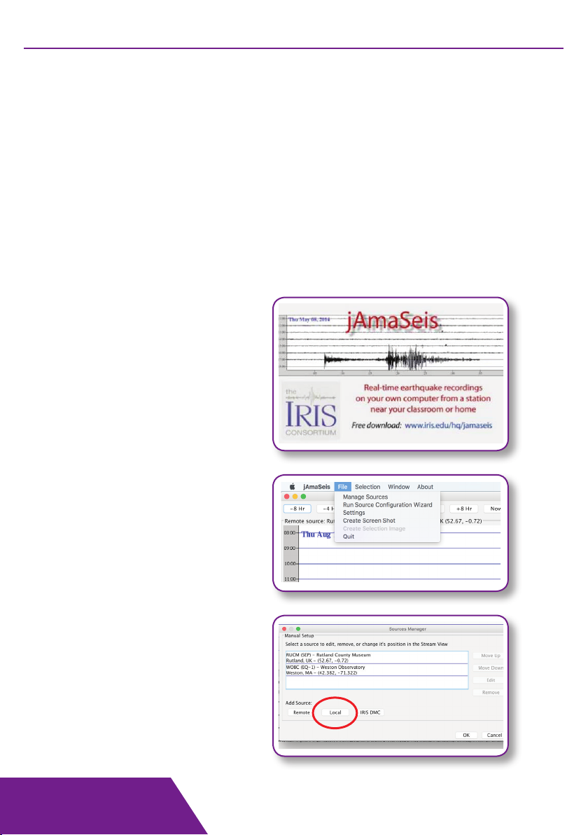
The simple design converts vertical ground vibrations into voltages and works in the
frequency range 1-2Hz up to 25 Hz. When combined with the mindsets digitiser and the
free educational datalogging software jAmaseis, the system allows schools and home
users to set up their own seismic monitoring station.
www.iris.edu/hq/jamaseis/
www.bgs.ac.uk/discoveringGeology/hazards/earthquakes/locatingQuakes.html
* Not included.

B.Y.O. Seismometer
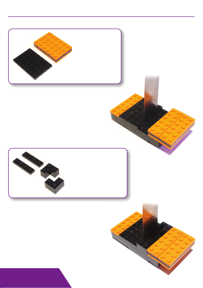
HINGE ASSEMBLY
Take one orange 2x6 plate and
place one black 2x2 plate in the
middle.
Place two black 1x2 plates onto
the ends of the orange piece.
Make two of these.
Place the two pieces from the
previous step side-by-side and
press the pre-assembled purple
tile sections into place.
There should be a gap between
the sections as shown here.
Required:
4 x Orange 2x6 plate
2 x Black 2x2 plate
4 x Black 1x2 plate
2 x Pre-assembled purple
taped tile sections.
Note the pre-taped purple tile
pieces.
Do not remove the tape.

B.Y.O. Seismometer
Take the two orange 2x6 plates
and press them on top.
This completes the hinge section.
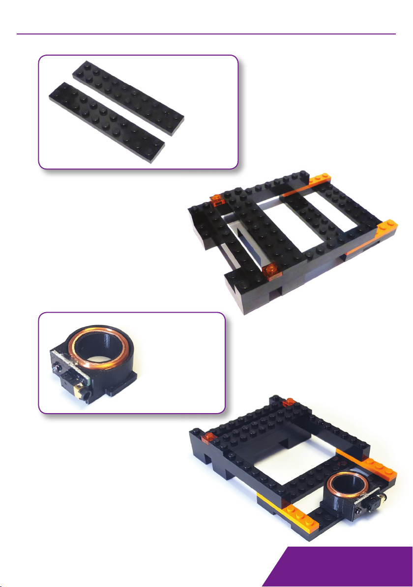
Required:
1 x Black 4x6 plate
2 x Black 1x10 block
1 x Orange 2x6 plate
Place the two black 1x10 blocks onto
the black 4x6 plate with two studs
overhanging one end as shown.
Take the orange 2x6 plate and place it
across the other end of the two 1x10
blocks.
ARMATURE ASSEMBLY

B.Y.O. Seismometer
Place one black 2x4 block onto the
black 4x6 plate at the end closer to
the orange piece.
Stand the flat metal spring up against
this block as shown here.
Place the second black 2x4 block
onto the remaining space on the
black 4x6 plate up against the
metal spring.
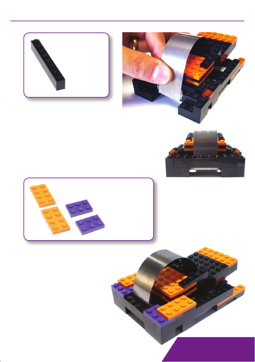
ARMATURE ASSEMBLY
Required:
2 x Black 2x4 block
1 x Steel spring strip
B.Y.O. Seismometer
Required:
2 x Black 2x2 corner block
2 x Black 1x4 plate
Place the two black corner pieces
onto the black 1x10 blocks next to the
hinge section.
Ensure that the face of these corner
pieces that is two studs long is against
the hinges.
See Fig.1.
Press the black 4x6 plate onto the top
alongside the orange 2x6 plate.
Push the hinge section onto the two
end studs of the black 1x10 blocks.
Required:
1 x Hinge section
1 x Black 4x6 plate
ARMATURE ASSEMBLY

B.Y.O. Seismometer
Required:
1 x Large rare earth magnet
1 x Small rare earth magnet
2 x Purple 1x1 stud
1 x Grey 1x1 stud
Press the small rare earth magnet into the
bottom of the grey 1x1 stud.
Turn this grey stud back up the correct way and
press the two purple 1x1 studs onto the top.
Place one black 1x4 plate across the
corner section and one side of the
hinge. Do this on both sides.
HINGE
HINGE
Fig.1
ARMATURE ASSEMBLY
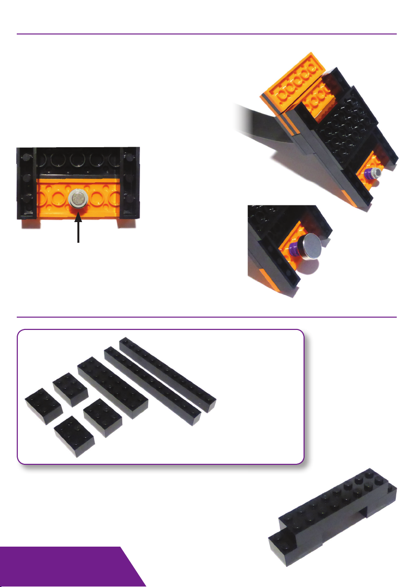
B.Y.O. Seismometer
Turn the armature section over and press this
small purple and grey section into the middle
circle of the orange 2x6 plate.
Note: This plate is at the
opposite end to the hinge plates.
Place the large rare
earth magnet onto
the small magnet.
Note: Take care
when handling
the large magnet
as it is very strong
and fingers can
get pinched!
Fit the black 2x8 block onto two of the black
2x3 blocks so that the 2x8 block is stepped
back by one stud at both ends.
Central circle.
Required:
2 x Black 1x12 block
1 x Black 2x8 block
4 x Black 2x3 block
ARMATURE ASSEMBLY
BASE ASSEMBLY
B.Y.O. Seismometer
Fit a black 1x6 plate onto an orange 1x6
plate so that all six studs are covered.
Do this twice.
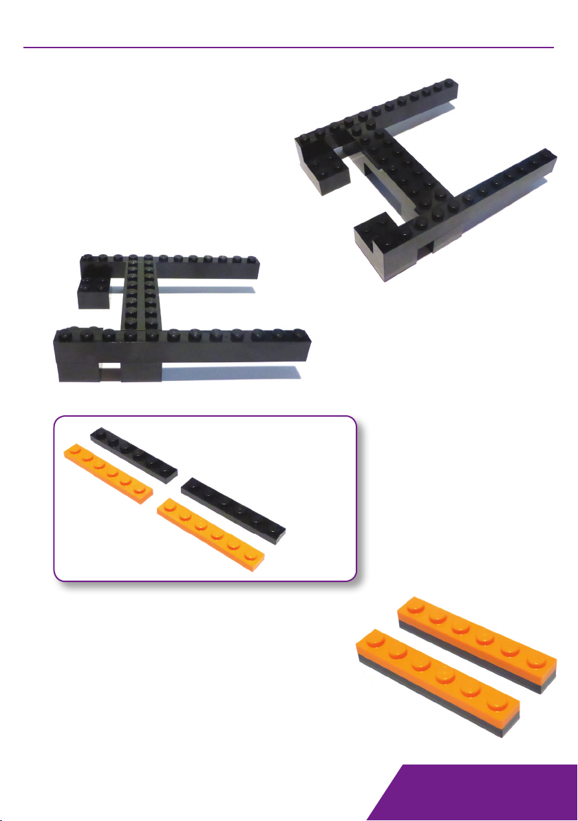
Place the black 1x12 blocks onto the
remaining ends of the 2x3 blocks
so that three ‘nobbles’ are over at one
end and seven are over the other end.
Fit the remaining black 2x3 blocks
under the side which has the three
studs. There should be a single
stud space between 2x3 blocks on both
sides.
Required:
2 x Black 1x6 plate
2 x Orange 1x6 plate
BASE ASSEMBLY
B.Y.O. Seismometer
Fit each of these parts to the
underneath of the 1x12 blocks
at the opposite ends to the 2x3
blocks.
The orange pieces should be
connected by three studs and
three protruding.
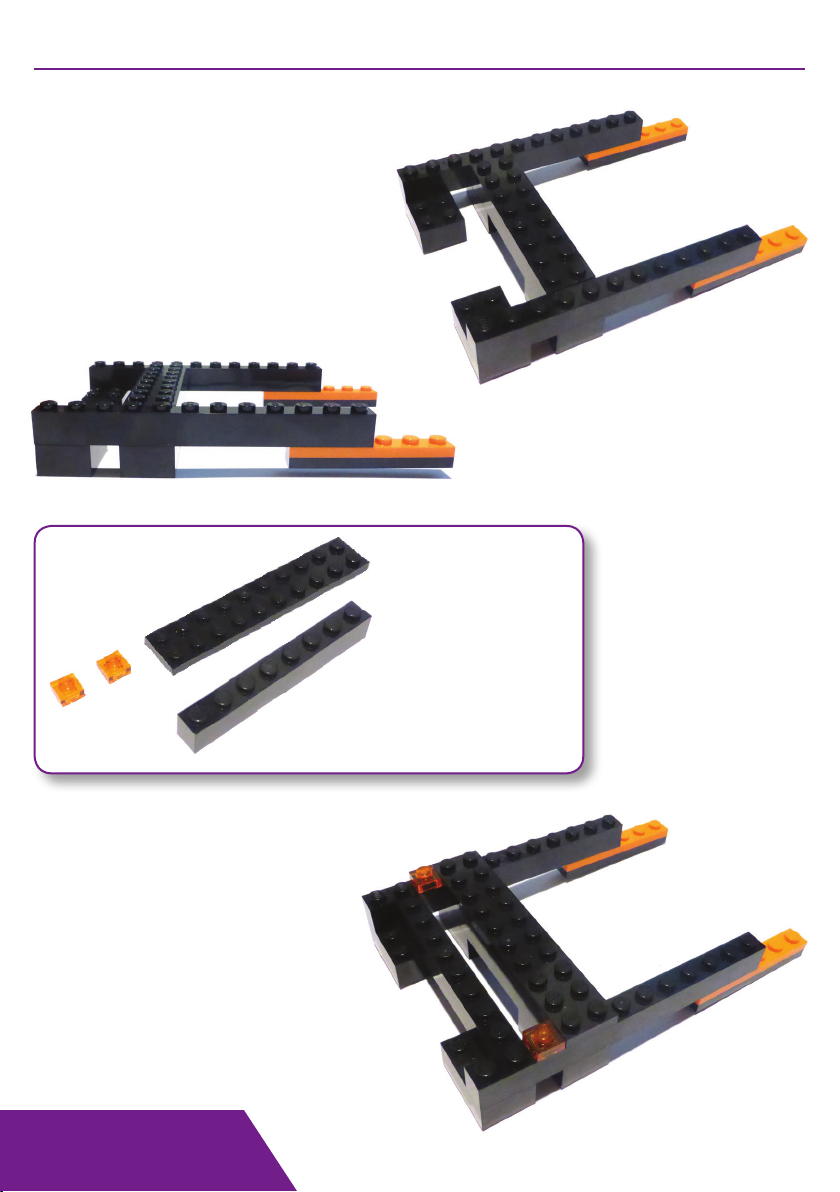
Place the black 2x10 plate onto
the 2x8 block and across the 1x12
blocks to lock them into position.
Fit the transparent orange tiles onto
the 1x12 blocks immediately next
to the 2x10 plate leaving a two stud
gap at the ends.
The 1x8 block is then fitted onto the
2x3 blocks one stud from the end of
the structure.
Required:
1 x Black 2x10 plate
1 x Black 1x8 block
2 x Transparent
orange 1x1 plate
BASE ASSEMBLY
B.Y.O. Seismometer
Fit the black 2x10 plates
underneath the black and
orange 1x6 plates so that each
one is level with the ends of
these plates, leaving a two
stud gap in between.
Required:
2 x Black 2x10 plate
BASE ASSEMBLY
Required:
1 x Coil assembly
Press the coil assembly onto
the 2x10 plate at the front of
the base so that it is central.

B.Y.O. Seismometer
FINAL ASSEMBLY
The rear of the hinge section (the
end with the flexible orange 2x6
section) is placed onto the black
2x10 plate which is on top of the
base section.
There should be a 2 stud gap at
both ends of this piece.
Check that the large
magnet can freely move
within the coil assembly.
It’s position can be
moved/adjusted easily
by hand.
The base section and
hinge section should now
be complete.
B.Y.O. Seismometer
Required:
1 x Black 1x8 block
FINAL ASSEMBLY
Required:
2 x Orange 2x4 plate
2 x Purple 2x3 plate
Press the two purple 2x3 plates
onto the back corners of the
base section.
They should be four studs
apart.
The orange 2x4 plates are
then placed on top of the
purple plates as shown.
Bend the steel spring back so that it
is against the side surface of the black
1x8 block already in place.
Push another 1x8 block in place next to the
existing one to sandwich the spring in place.
The spring may protrude below
the 1x8 blocks as shown here, right.
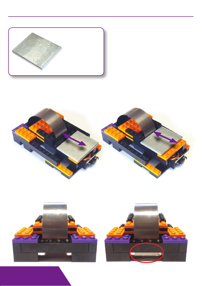
B.Y.O. Seismometer
Required:
1 x Steel weight
Position the steel weight onto the front platform as shown.
Ideally, the top of the large magnet should hover level with the top edge of the coil.
To achieve this the weight can be positioned further forward or backward and you may
need to remove one of the small purple studs holding the magnets.
The steel spring can be slid further down between the
1x8 blocks to adjust the tension of the spring.
The further it is pressed down, the tighter the spring.
SETTING UP THE SEISMOMETER
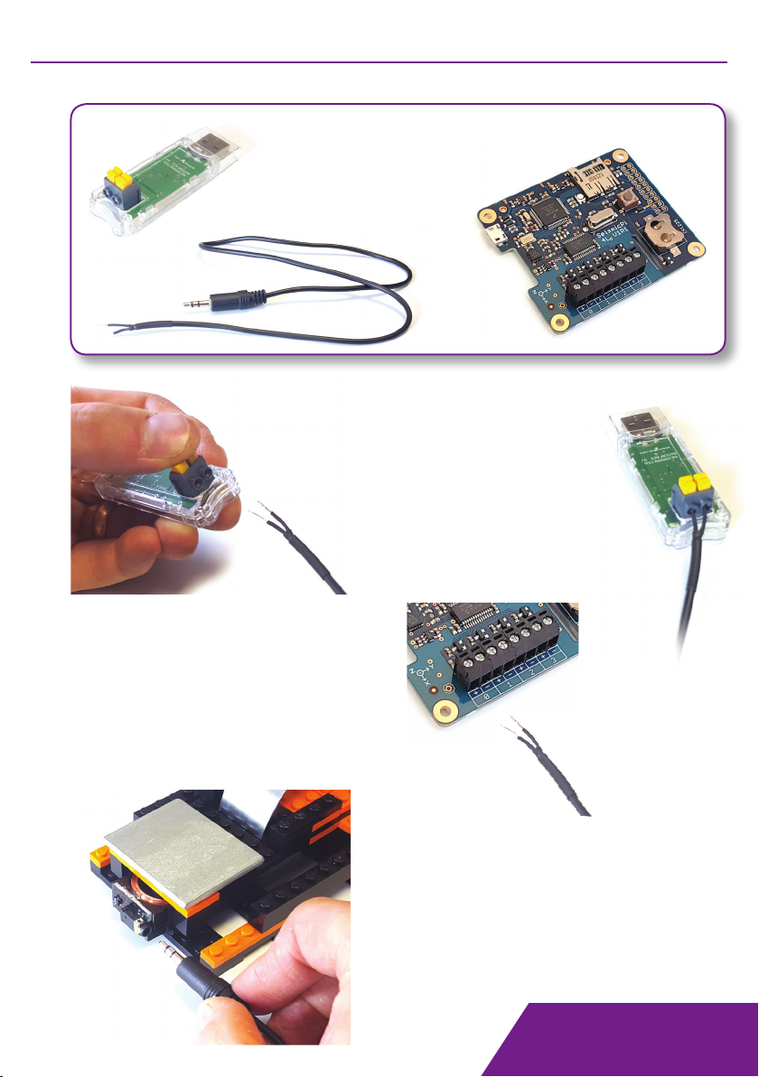
B.Y.O. Seismometer
SeismicPi HAT:
Loosen the two screws for input ‘0’.
Insert the bare wires into the holes
in the side of the terminal block and
retighten the screws.
Connect the other end of
this lead to the socket on
the coil assembly.
CONNECTING THE SEISMOMETER
USB Seismometer Interface:
Firmly press the yellow buttons down to
open the holes of the terminal block.
Feed the bare wires into the two holes and
release the yellow terminals.
Check that both wires are held securely.
Required:
Either:
1 x USB seismometer Interface OR;
1 x SeismicPi HAT
1 x 3.5mm audio lead
B.Y.O. Seismometer
Driver installation
On Windows systems a driver needs to be installed to allow the interface to show as a
Virtual Com Port. The driver file can be downloaded from www.mindsetsonline.co.uk.
When the device is connected for the first time, Windows will ask for a driver.
Enter the location of the driver file, and Windows should then complete the installation.
Note: it may be necessary to disable ‘require driver signing’ in Windows.
The USB seismometer interface appears as a Virtual Com Port when connected via USB,
hence can be used with software such as jAmaseis, which can be found at:
www.iris.edu/hq/jamaseis/
jAmaseis Setup
Open jAmaseis
File -> Manage sources
Add local source
USING THE SEISMOMETER
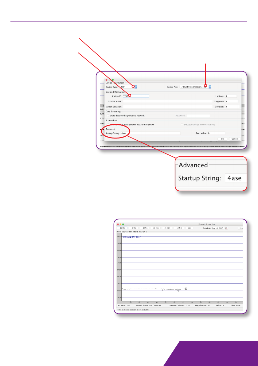
B.Y.O. Seismometer
Set device type to SEP
Enter a station ID
(Other information
is optional).
Startup String:
USB Interface. Use ‘4a’:
• Gain to x4
• Sample rate to 20.032 SPS
SeismicPi HAT. Use ‘4ase’:
• Gain to x4
• Sample rate to 32 SPS
• Single channel
• External input.
OK to confirm & OK to exit
the sources manager.
Your stream should now be
added to the stream view.
Select device port if more than
one is available.
Note: Device must be plugged
in for it to appear here.
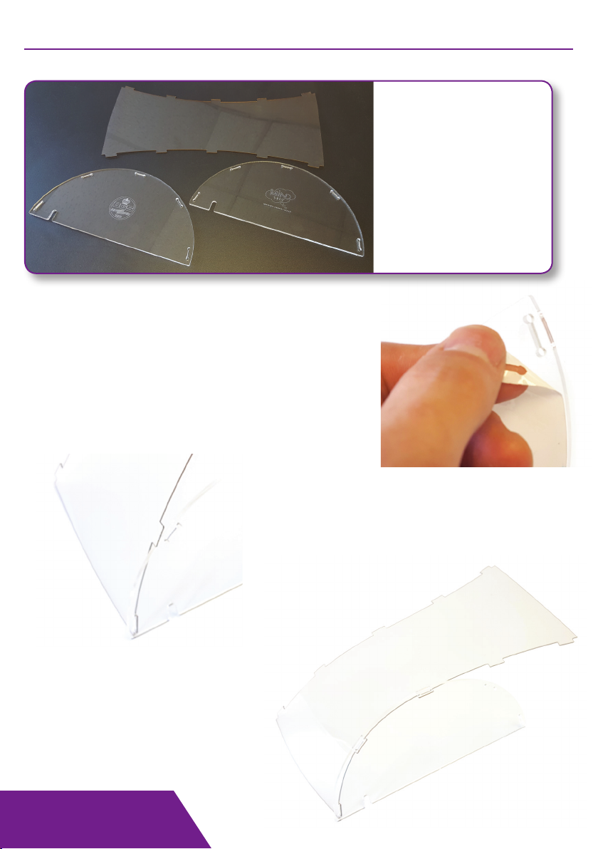
B.Y.O. Seismometer
Required:
1 x Transparent top piece
2 x Transparent side piece
DOME ASSEMBLY
Take the long top piece and starting at
one end, start inserting the tabs into the
slots on one of the side pieces.
Ensure the logo is on the outer face.
One-by-one, insert each tab until
all five are in place.
This must be done gently to avoid
any damage to the side pieces.
Peel the protective film from each piece.
This is best achieved by scratching your nail along the
edge of the material to roughen up the coating and
then peeling back.
Putting some sticky tape onto the coating with the
tape hanging over the edge can also be helpful.

B.Y.O. Seismometer
DOME ASSEMBLY
Repeat the process for the
opposite side.
Once all tabs are in place, the
structure will be rigid and stable.
When placing the dome over
the seismometer, make sure the
connection wire is in one of the
slots provided so that the dome
can still sit flat.

B.Y.O. Seismometer
Designed, Manufactured and supplied by:
Mindsets (UK) Ltd
01992 716 052
www.mindsetsonline.co.uk
© 2018 Mindsets (UK) Ltd
This manual suits for next models
1
Table of contents
Popular Toy manuals by other brands


Jamara
Jamara Islander EP instruction manual

Power Wheels
Power Wheels J8760 Owner's manual with assembly instructions

Thames & Kosmos
Thames & Kosmos Gyroscopes & Flywheels Experiment manual

HobbyZone
HobbyZone HobbyZone instruction manual

Mega Bloks
Mega Bloks Pirates of the Caribbean manual

Accucraft trains
Accucraft trains D&RGW K37 2-8-2 instruction manual


