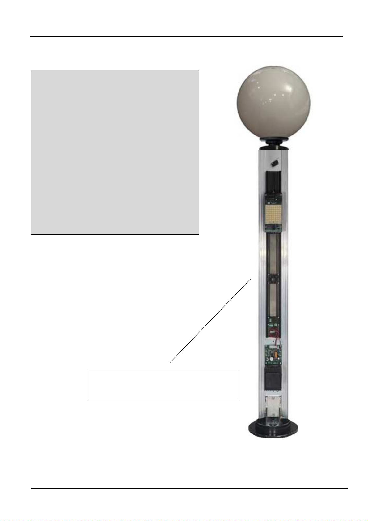
MITECH Garden/Tower-MICRO Series Technical specifications

Garden/Tower-MICRO Rev. 2 - 03/2015 –
MITECH srl reserves the right to change the information in this document without warning.
English
Series
G
GG
G
G
GG
GA
AA
A
A
AA
AR
RR
R
R
RR
RD
DD
D
D
DD
DE
EE
E
E
EE
EN
NN
N
N
NN
N-
--
-
-
--
-T
TT
T
T
TT
TO
OO
O
O
OO
OW
WW
W
W
WW
WE
EE
E
E
EE
ER
RR
R
R
RR
R
M
MM
M
M
MM
MI
II
I
I
II
IC
CC
C
C
CC
CR
RR
R
R
RR
RO
OO
O
O
OO
O
Use and installation manual

Garden/Tower-Magnus Use and installation manual Page 2di 20
Index
Anti-intrusion column 3
Main com onents 4
Additional com onents 5
General installation instructions 6
Mounting o tions 6
Wall mounting 6
Ground mounting 7
Fixing the column to the base 8
Inserting the cover and closing the column 9
Mounting the lam 10
Exam les of installation 11
Exam le of how to rotect an inde endent building 12
Column su ly 13
Microwave Barrier Detection System 14
Introduction 14
Technical s ecifications and connections
15
Warnings and general characteristics 16
Notes 17-18-19

Garden/Tower-MICRO Use and installation manual Page 3of 20
Anti-intrusion column
View of the
column
without
protection cover
IMPORTANT
- Power the device using the
13.8 Vdc stabilised voltage only.
- In order for the column to work
correctly, ensure the power voltage
never falls below 12 Vdc.
- It is imperative you switch on the
temperature control system for both
internal and external installations
(power –supply 24Vac).

Garden/Tower-MICRO Use and installation manual Page 4of 20
Main com onents
2
3
1
4
Part
PartPart
Part
Quantity
QuantityQuantity
Quantity
Description
DescriptionDescription
Description
1 1 Aluminum profile
2 1 IR polycarbonate cover
3 1 Upper cover
1 Lower cover
5 1 Receiver or transmitter
microwave device
6 1 Tamper
5
6

Garden/Tower-MICRO Use and installation manual Page 5of 20
Additional com onents
1A
3
8
2
5
6
1B
4
7
Components included
Components includedComponents included
Components included
(TW = Tower – GAR = Garden)
Part
PartPart
Part
Quantity
QuantityQuantity
Quantity
Description
DescriptionDescription
Description
1A
(TW e GAR)
1
Ground fixing base
1B
(TW e GAR)
1
Wall fixing base
2
(TW e GAR)
1
Bracket
3
(TW e GAR)
Screws with
washers
(TW e GAR)
3
Clamps
5
(solo GAR)
1
Upper lamp cover
6
(solo GAR)
1
Lamp holder
Optional
OptionalOptional
Optional
Pa
PaPa
Pa
rt
rtrt
rt
Quantity
QuantityQuantity
Quantity
Description
DescriptionDescription
Description
7
(only GAR)
GAR
LAMP
CO/WH
Globe
(32 cm diameter, colour
cognac CO or white WH)
8
(TW e GAR)
GAR
POW
Dual power supply
unit
(normally supplied
separately, on request
it can be inserted inside
the column)
9
(only TW)
TW
CAP-PR
A
nti
-
removal
pressure cap
9

Garden/Tower-MICRO Use and installation manual Page 6of 20
General installation instructions
1. After installing the column, make sure that it is perfectly closed with the watertight
covers supplied.
2. Make sure that the path between the sensors is free and that there are no obstacles
that could affect the communication between the optical assemblies of the transmitters
and receivers that could interfere with the beams (i.e. branches, plants, leaves, snow,
etc).
3. Verify that the optical path of the transmitter used by the receiver column is not exposed
to direct sunlight at dawn and sunset.
4. If possible, do not use switching power supplies that cause disturbance to power
supplies when amplified by optically synchronized systems.
Mounting o tions
Columns may be mounted in two ways:
1. with a specific wall mounting base
2. with a specific ground mounting base.
Which in turn may be fixed in two ways:
•with clamps, fixing the base to a plinth
•with fixing gussets
Wall mounting
Wall mountingWall mounting
Wall mounting
Drill 4 holes of Ø 8 mm in the wall, level with the
base fixing holes.
Insert TE M8 steel gussets (not supplied) and fix
the base
200
210
Ø
33

Garden/Tower-MICRO Use and installation manual Page 7of 20
Ground mounting
Ground mountingGround mounting
Ground mounting
with clamps, fixing the base to a plinth
This fixing method is the most secure.
It requires a cement base in which to anchor
the clamps provided.
Ensure the plinth contains a tube (Ø 20 mm)
through which to thread the cables.
with fixing gussets
Drill 3 holes of Ø 8 mm in the ground, level
with the base fixing holes.
Insert TE M8 steel gussets (not supplied) and
fix the base.
210
200
210
Ø
33
200
Ø33
200

Garden/Tower-MICRO Use and installation manual Page 8of 20
Fixing the column to the base
Insert the lower cover into the base guide.
Insert the aluminium profile into the base
guide and into the relevant slot in the lower
cover.
Insert the connecting bracket between the
lower cover and the aluminium profile.
Screw 2 TE M6x20 screws through the
bracket and the base and 2 TE M6x25 screws
through the bracket and the profile.
M6x25
M6x20
squadretta

Garden/Tower-MICRO Use and installation manual Page 9of 20
Inserting the cover and closing the column
Insert the polycarbonate cover from above,
making it slide down as far as the column
base and inserting it into the lower cover.
Place the upper cover and screw it to the
column by means of 2 O-ring screws (supplied).

Garden/Tower-MICRO Use and installation manual Page 10 of 20
Mounting the lam
Place the specific upper cover that connects to the
lamp holder, ensuring the power cables are properly
threaded.
Screw the cover to the column by means of
2 O-ring screws (supplied).
Connect the wires to the lamp holder terminal.
Fix the lamp holder to the cover using the 2
Allen screws found at the sides
(5 mm spanner).
Insert the bulb.
Place the lamp shade on the supporting base
and turn it clockwise.
Fix it in place using the screw found on the
supporting base.
Viti a
brugola
vite

Garden/Tower-MICRO Use and installation manual Page 11 of 20
Exam les of installation
4 sides perimeter check
4 sides perimeter check4 sides perimeter check
4 sides perimeter check
solution 1: 8 terminal columns (each column has only one TX or RX device).
4 sides perimeter check
4 sides perimeter check4 sides perimeter check
4 sides perimeter check
solution 2: 4 complete bidirectional columns (each column has a TX + one RX device).
Check of just one side
Check of just one sideCheck of just one side
Check of just one side
solution 3: 2 terminal columns (each column has just one TX or RX device)
To be used when it is sufficient to protect just one side because the remaining perimeter is already protected or
inaccessible.
TX RX
TX
RX
RX TX
TX
TX
RX
RX
PROTECTED
AREA
TX RX
RX TX
TX
RX TX
RX
PROTECTED
AREA
PROTECTED
AREA

Garden/Tower-MICRO Use and installation manual Page 12 of 20
Example of how to protect an independent building
Example of how to protect an independent buildingExample of how to protect an independent building
Example of how to protect an independent building
The electromagnetic waves transmitted are high frequency to guarantee maximum protection.
WARNINGS
Ensure no interference is caused by the presence of photocells for
automatic gates or microwave sensors, as these may blind the barriers
(ex. video infrared lighting for night vision)
high frequency
electromagnetic waves
transmitted by the columns
columns

Garden/Tower-MICRO Use and installation manual Page 13 of 20
Column su ly
Example of supply of RX terminal column using the GAR POW dual power supply unit.
220 Vac
6 5 4 3 2 1
GND
-12 Vdc
+12 Vdc
Vin
WARNINGS
To function correctly the column needs 230 Vac filtered and stabilized
voltage supply.
Therefore check the electrical system before powering up.
GARPOW
MICROWAVE

Garden/Tower-MICRO Use and installation manual Page 14 of 20
Microwave Barrier Detection System
Introduction
IntroductionIntroduction
Introduction
The current manual uses the following abbreviations:
DZ -detection zone
TU -transmitting unit
RU -receiving unit
TU and RU are placed at the opposite ends of the guarded area.
TU emits electromagnetic waves in the direction of RU. RU receives these waves, processes
them into an electric signal and analyses this signal.
The person who crosses the DZ, triggers the modulation of the signal at the entry of the RU.
The depth of the modulation and the form of signal depend on the size and mass of the
person, the place where the area is crossed, the relief of the land and the speed of movement.
IMPORTANT
To use, no aligning kit or programming software are required.
RU
TU
CONNECTOR
TU
RU
COVER not used not used
ALARM not used ALARM N.C.
contact
SERIAL
GND/B/A serial
communication serial
communication
POWER
GND Vin power
12 / 36 VDC power
12 / 36 VDC

Garden/Tower-MICRO Use and installation manual Page 15 of 20
Technical s ecifications and connections
Parametro Valore
Lobo dimensions:
- height
- opening
max 2,50 m
max 1,0 m
Operating temperature da -40°C a +65°C
DZ length da 1 a 200 m
Range of detection speeds da 0,1 a 10,0 m/s
Range of working supply voltage da 12 a 36 Vdc
Maximum current required at the working supply voltage of 24V
- TX
- RX
80 mA
100 mA
Maximum recovery time of the stand-by system after notification of an alarm 10 s
Parameters of signal, switched with the contacts of the output circuit:
- maximum current, constant or alternate
- maximum voltage
30 mA
72 V
Minimum signal duration 5 s
Operating frequency da 24.00 a 24.25 GHz
C
CC
Connections
onnectionsonnections
onnections
After fixing the base (see the installation options on p. 6 and how to fix the column to the base
on p. 8 of the manual) and powering the column (see page 15), follow the following
instructions:
1. carry out the manual adjustment of the device by rotating the TU and RU units in the
desired direction till the alarm signal switches off.
To carry out the adjustment, loosen the fixing screws of the TU and RU units.
Take care, the rotations must be slow and gradual.
Never rotate violently.
2. Once the adjustment has been completed, tighten the fixing screws of the TU and RU
units.

Garden/Tower-MICRO Use and installation manual Page 16 of 20
WARNINGS
1. When carrying out the work for preparing the detector for use as well as in using it, the current
rules on technical safety have to be observed in the use of electric installations.
2. The emission level of the TU of the detector, in accordance with the effective norms for personal
safety of those, who are professionally, allows non-stop working.
To guarantee the maximum reliability of the sensor operation, the horizontal distance between the
DZ axis and the edge of the exclusion zone must be:
- at least 1.2m for a section up to 50m long
- at least 1.5m for a section between 50m and 100m long
3. In the exclusion zone the maximum height of the unevenness of the ground and the snow and
grass cover shall not exceed 0.3 m
The use of the sensor is admitted when the snow or grass cover exceeds the stated value.
However the sensor might not pick up a person that is moving on the snow or grass. In this
case the unit height must be modified. If the above requirements are not complied with, the
characteristics of the device might be altered.
4. If the maximum level of the signal received is reached during the adjustment, when the units are
directed towards reflective surfaces (fences, ground, etc.), it is necessary to change the position
and orientation of the aerials.
5. A possible cause for the false alarms of the device might be the RU unit receiving the emissions of
different Tus.
6. Carry out testing for no less than 3 days and check the crossing sensing at least twice in 24 hours.
7. The device works properly and does not give false alarms even in the event of disturbances
caused by:
a) the movement of a person at the following distances from the DZ axis:
- 1.5m in length on a 50m surface;
- 2.0m in length on a 100m surface;
b) the movement in the DZ of small animals (birds) at a distance greater than 3m from the TU or
RU units.
General characteristics
GARDEN/TOWER
MICRO
Max. operating range outdoors 100 m (200 m on request)
Min. operating range outdoors 5 m
Column height 1,5 m – 2,0 m - 2,5 m – 3,0 m
Power-supply 12Vdc – recommended 13,8 Vdc
Maximum absorption 570 mA (TX 200 mA – RX 370 mA)
model column by 3 meters in height
Operating temperature –35°C +70°C
Vertical alignment angle 30°
Horizontal alignment angle 180°
Detection system AND / OR on Tx and Rx AND remote
Alarm output Contact of exchange relay NC/NA
Tamper output NC contact
MW signal High frequency electromagnetic waves
Lobe height 2,5 m
Lobe opening 1,0 m
Serial communication
RS485
MW alignment Manual
LED indicators Power supply, blinding, heating, low signal,
alarm, detection
MW LED warning Alarm
Class of protection IP 65
Full warranty 2 years

Garden/Tower-MICRO Use and installation manual Page 17 of 20
NOTES:
…………………………………………………………………………………………………………..
…………………………………………………………………………………………………………..
…………………………………………………………………………………………………………..
…………………………………………………………………………………………………………..
…………………………………………………………………………………………………………..
…………………………………………………………………………………………………………..
…………………………………………………………………………………………………………..
…………………………………………………………………………………………………………..
…………………………………………………………………………………………………………..
…………………………………………………………………………………………………………..
…………………………………………………………………………………………………………..
…………………………………………………………………………………………………………..
…………………………………………………………………………………………………………..
…………………………………………………………………………………………………………..
…………………………………………………………………………………………………………..
…………………………………………………………………………………………………………..
…………………………………………………………………………………………………………..
…………………………………………………………………………………………………………..
…………………………………………………………………………………………………………..
…………………………………………………………………………………………………………..
…………………………………………………………………………………………………………..
…………………………………………………………………………………………………………..
…………………………………………………………………………………………………………..
…………………………………………………………………………………………………………..
…………………………………………………………………………………………………………..
…………………………………………………………………………………………………………..
…………………………………………………………………………………………………………..
…………………………………………………………………………………………………………..
…………………………………………………………………………………………………………..
…………………………………………………………………………………………………………..
…………………………………………………………………………………………………………..
…………………………………………………………………………………………………………..
…………………………………………………………………………………………………………..
…………………………………………………………………………………………………………..
…………………………………………………………………………………………………………..

Garden/Tower-MICRO Use and installation manual Page 18 of 20
…………………………………………………………………………………………………………..
…………………………………………………………………………………………………………..
…………………………………………………………………………………………………………..
…………………………………………………………………………………………………………..
…………………………………………………………………………………………………………..
…………………………………………………………………………………………………………..
…………………………………………………………………………………………………………..
…………………………………………………………………………………………………………..
…………………………………………………………………………………………………………..
…………………………………………………………………………………………………………..
…………………………………………………………………………………………………………..
…………………………………………………………………………………………………………..
…………………………………………………………………………………………………………..
…………………………………………………………………………………………………………..
…………………………………………………………………………………………………………..
…………………………………………………………………………………………………………..
…………………………………………………………………………………………………………..
…………………………………………………………………………………………………………..
…………………………………………………………………………………………………………..
…………………………………………………………………………………………………………..
…………………………………………………………………………………………………………..
…………………………………………………………………………………………………………..
…………………………………………………………………………………………………………..
…………………………………………………………………………………………………………..
…………………………………………………………………………………………………………..
…………………………………………………………………………………………………………..
…………………………………………………………………………………………………………..
…………………………………………………………………………………………………………..
…………………………………………………………………………………………………………..
…………………………………………………………………………………………………………..
…………………………………………………………………………………………………………..
…………………………………………………………………………………………………………..
…………………………………………………………………………………………………………..
…………………………………………………………………………………………………………..
…………………………………………………………………………………………………………..
…………………………………………………………………………………………………………..
…………………………………………………………………………………………………………..

Garden/Tower-MICRO Use and installation manual Page 19 of 20
…………………………………………………………………………………………………………..
…………………………………………………………………………………………………………..
…………………………………………………………………………………………………………..
…………………………………………………………………………………………………………..
…………………………………………………………………………………………………………..
…………………………………………………………………………………………………………..
…………………………………………………………………………………………………………..
…………………………………………………………………………………………………………..
…………………………………………………………………………………………………………..
…………………………………………………………………………………………………………..
…………………………………………………………………………………………………………..
…………………………………………………………………………………………………………..
…………………………………………………………………………………………………………..
…………………………………………………………………………………………………………..
…………………………………………………………………………………………………………..
…………………………………………………………………………………………………………..
…………………………………………………………………………………………………………..
…………………………………………………………………………………………………………..
…………………………………………………………………………………………………………..
…………………………………………………………………………………………………………..
…………………………………………………………………………………………………………..
…………………………………………………………………………………………………………..
…………………………………………………………………………………………………………..
…………………………………………………………………………………………………………..
…………………………………………………………………………………………………………..
…………………………………………………………………………………………………………..
…………………………………………………………………………………………………………..
…………………………………………………………………………………………………………..
…………………………………………………………………………………………………………..
…………………………………………………………………………………………………………..
…………………………………………………………………………………………………………..
…………………………………………………………………………………………………………..
…………………………………………………………………………………………………………..
…………………………………………………………………………………………………………..
…………………………………………………………………………………………………………..
…………………………………………………………………………………………………………..
…………………………………………………………………………………………………………..

Garden/Tower-MICRO Use and installation manual Page 20 of 20
MITECH S.r.l.
Main Office:
Via Roncaglia, 14 - 20146 Milano -Italy
Telefono: +39 02.48006383
Fax: +39 02.48025620
Production site:
Via Ramazzone, 23
43010 - Fontevivo (Parma) - Italy
Email: tech@mitech-security.com
www.mitech-security.com
Table of contents
Popular Outdoor Light manuals by other brands

CristalRecord
CristalRecord NASSIRA 60W quick start guide

Clarke
Clarke SAL100B Assembly & operating instructions

JONATHAN Y
JONATHAN Y JYL6203A quick start guide

Westinghouse
Westinghouse 63487 instruction manual

HumanTechnik
HumanTechnik lisa operating instructions

Maretti
Maretti GROUND ROUND 18 quick start guide