Mitsubishi MOTORS Lancer Evolution-VIII Instruction manual


LANCER
EVOLUTION VIII
FOREWORD
This manual contains details of the main changes to the ’03
model Lancer Evolution VIII. Since only differences to the
Lancer Evolution VII have been included, lease use this
manual in conjunction with the relevant ages in the material
reviously ublished.
We recommend that work is carried out with careful
reference to this manual, to ensure that servicing is done
correctly and quickly, so that vehicle erformance is
maintained.
This manual is based on the current model (January 2003).
Please bear in mind that as a result of subsequent changes
to vehicle s ecifications, some information may not
corres ond to more recently ublished details.
All the units shown in this manual follow the internationally
recognised SI unit system. Please note that the ractice of
using the old units together with SI units has been dro ed.
(Please note, however, that figures and units s ecified on
various forms may still use the old units)
January 2003
MITSUBISHI MOTOR CORPORATION
CONTENTS
General
Engine
Fuel
Engine Cooling
Intake and E haust
Engine Electrical
Engine and Emission Control
Manual Transmission
Front A le
Rear A le
Engine and Transmission Mounting
Body
E terior
Interior and SRS Airbag
Chassis Electrical
00
11
13
14
15
16
17
22
26
27
32
42
51
52
54
Any o inions, requests, or questions concerning this
manual, should be written on the ‘Servicing Comment Form’
at the end, and sent to us by fax.

Related materials
WARNING REGARDING SERVICING OF VEHICLES FITTED WITH SRS AIR BAGS · SEAT BELTS WITH
PRE-TENSIONERS
Warning
1. Improper servicing or maintenance of any SRS air bag or pretensioner fitted seatbelt component, or
related parts, could cause major injury as a result of the unintentional setting-off (incorrect
deployment) of the SRS air bag or pretensioner fitted seatbelt, or non-operation.
2. When they could be subject to the effects of heat during the painting process, please remove the
SRS-ECU, driver side air bag module, passenger side air bag module, pretensioner fitted seatbelt,
and clock spring, as follows:
• 93°C and above: driver side air bag module, passenger side air bag module, clock spring
• 90°C and above: pretensioner fitted seat belts
3. Service or maintenance of any SRS air bag or pretensioner fitted seatbelt components or related
parts must be performed by an authorised MITSUBISHI dealer.
4. This manual must be consulted (with special reference to Chapter 52B SRS Air Bag) before
any servicing or maintenance is carried out on SRS air bag or pretensioner fitted seatbelt
components or related parts.
Note
Sections titles with an asterisk (*) indicate areas where s ecial attention must be aid to SRS airbags and retensioner fitted
seatbelts.
Title No. Issue date
New model manuals
• Mirage, Lancer
• Mirage, Lancer
• Mirage, Lancer
• Mirage, Lancer
• Lancer
• Mirage, Lancer
• Lancer
• Lancer
• Lancer Sedia
• Lancer Sedia
• Lancer Evolution VII
• Lancer Sedia
• Lancer Sedia
• Lancer Evolution VII
• Lancer Sedia
• Lancer Evolution VII
1036F30
1036F31
1036F32
1036F33
1036F34
1036F35
1036F36
1036F37
1036K30
1036K31
1036K32
1036K33
1036K34
1036K35
1036K36
1036K37
10/1995
1/1996
8/1996
7/1997
1/1998
10/1998
1/1999
12/1999
5/2000
7/2000
1/2001
5/2001
5/2001
1/2002
5/2002
1/2003
Worksho Manuals
• Lancer Sedia
• Lancer Sedia (su lement)
• Lancer Evolution VII (su lement)
• Lancer Sedia (su lement)
• Lancer Sedia (su lement)
• Lancer Evolution VII (su lement)
• Lancer Sedia (su lement)
1036k00
1036K01
1036K02
1036K03
1036K04
1036K05
1036K06
5/2000
7/2000
1/2001
5/2001
10/2001
1/2002
5/2002
Body edition Worksho Manuals
• Mirage, Lancer (su lement)
• Lancer Sedia
• Lancer Sedia (su lement)
• Lancer Evolution VII (su lement)
• Lancer Sedia (su lement)
1036F32
1036K50
1036K51
1036K52
1036K53
8/1996
5/2000
7/2000
5/2001
10/2001
Electrical Wiring Diagrams Worksho Manuals
• Lancer Evolution VIII 1036K77 1/2003
Engine Worksho Manuals
• 4G6 engine
• 4G6 engine (su lement) 1039G46
1039G63 1/2001
1/2003
Transmission Worksho Manual
• W5M51 manual transmission
• W5M51 manual transmission (su lement)
• W6MAA manual transmission
1039M17
1039M22
1039M23
1/2001
1/2003
1/2003

GENERAL - MODEL LINE-UP, APPLIED VEHICLES 00-1
SECTION 00
GENERAL
CONTENTS
Model line-up
Note
[] New model [] Continued model [X] Discontinued model
Applied vehicles
GH-CT9A: CT9A-0200001 ~
Model line-up..............................................1
Applied vehicle numbers ..........................1
Troubleshooting and Inspection ..............2
Model Version ’03 Model Grade Engine Model Transmission Fuel System
GH-CT9A SNDFZ
SYGFZ
SJDFZ
SJGFZ
X
RS
GT-A
RS
GSR
4G63
(2 000 DOHC 16 valve
intercooler turbo)
W5M51 (4WD, 5M/T)
W5A51 [4WD, INVECS-II
S orts mode 5 A/T (with
steering shift switch)
W6MAA (4WD, 6 M/T)
MPI
GENERAL - TROUBLESHOOTING AND INSPECTION
00-2
TROUBLESHOOTING AND INSPECTION
Diagnosis Functions
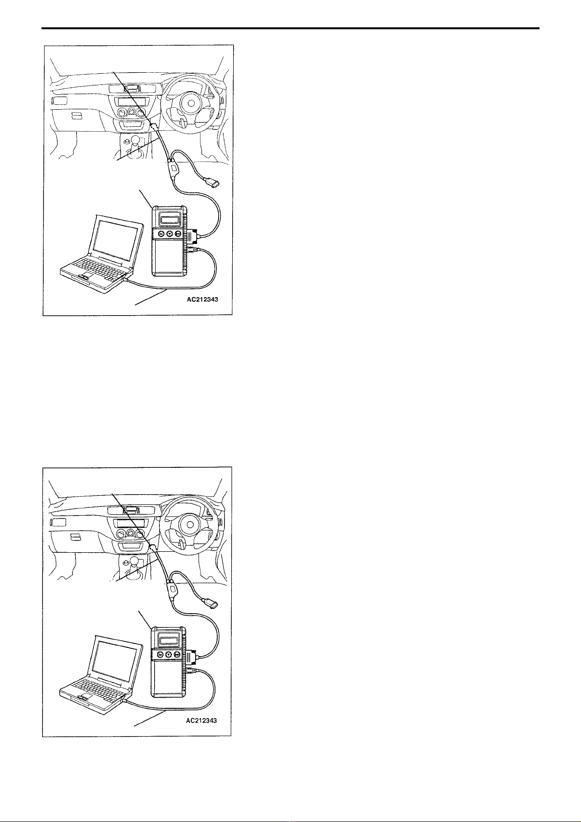
Reading Diagnosis Code
Connect the MUT-III to 16 in diagnosis connector and read diagnosis code
as described below.
NB. Please refer to the User Manual for a detailed ex lanation of how to
use the MUT-III.
(1) Check that the ignition switch is in the LOCK (OFF) osition.
(2) Connect s ecial V.C.I. (MB991824) and PC with s ecial USB cable
(MB991827).
(3) Connect s ecial MUT-III main harness B (MB991911) to V.C.I.
(4) Connect MUT-III main harness B to vehicle diagnosis connector.
(5) Turn V.C.I. ower switch ON.
(6) After switching V.C.I. ON, the green V.C.I. indicator light should come on.
(7) Start u the PC MUT-III system, and turn vehicle switch to the ON
osition.
(8) Read diagnosis code.
(9) When disconnecting, turn ignition switch to LOCK (OFF) osition, and
follow reverse rocedure.
Diagnosis Code Deletion
Connect MUT-III to diagnosis connector in the same way as for ‘Reading
Diagnosis Codes’, then delete diagnosis codes.
MUT-III main harness B
USB cable
Diagnosis connector
MUT-III main harness B
USB cable
Diagnosis connector
V.C.I.
V.C.I.

4G6 ENGINE – GENERAL, SEALANTS, SPECIAL TOOLS 11A-1
SECTION 11A
ENGINE
CONTENTS
4G6 ENGINE
General
The servicing information s ecified below accom anies changes to the 4G63-MPI-T/C engine installed on the new Lancer
Evolution VIII. Other servicing information remains the same.
• The crank angle sensor and O2sensor connector have been changed
• The timing belt front cover is now s lit into 2
Sealants
Note
( ) are original roducts
Special Tools
Tool
Number Name Function
MD998772 Valve s ring com ressor Valve s ring com ression
MD998737 Valve stem seal installer Valve seal stem installation
General .......................................................1
Sealants .....................................................1
Special Tools .............................................1
Engine adjustment ....................................2
1. Checking com ression ressure .....................2
Camshaft, valve stem seals .....................2
Timing belt, timing belt B........................11
Location Name
Rocker cover
Rocker cover gasket
Cylinder head
Semi-dry sealant: Three Bond 1207D (MZ100168) (contains
150g)
Camshaft end seal Semi-dry sealant: Three Bond 1211 (MZ100057) (contains
100g)
Camshaft osition sensor su ort Semi-dry sealant: Three Bond 1207F (MZ100191) (contains
150g)

4G6 ENGINE – SPECIAL TOOLS, ENGINE ADJUSTMENT, CAMSHAFT, VALVE STEM SEAL
11A-2
Tool Number Name Function
Camshaft oil seal insertion
ENGINE ADJUSTMENT
1. Checking compression pressure
The crank angle sensor connector osition has been
changed.
CAMSHAFT, VALVE STEM SEAL
Removal and Fitting
Caution
1. When Brembo brake callipers are used, there is concern over paint peeling off, so when doing servicing work,
make sure they are not scratched by other components and tools. Furthermore, if any brake fluid gets onto the
calipers, it should be wiped off immediately.
2. The fitting and removal of parts marked with an * should be carried out for each cylinder.
Jobs to do before removal and after fitting
• Removal and fitting of undercover (refer to Cha ter 51 Front Bum er)
• Checking drive belt tension <only after fitting>
• Draining and filling of coolant
• Removal and fitting of air duct
• Removal and fitting of air i e C (refer to Cha ter 15 Intercooler)
• Removal and fitting of timing belt (refer to P.11A-12)
crank angle sensor
connector
MD998713 Camshaft
Oil seal
Installer

4G6 ENGINE- CAMSHAFT , VALVE STEM SEAL 11A-3
Removal rocedure
1. Breather hose
• Air bag ASSY
(refer to Cha ter 15-2 Secondary Air Control
System)
2. Centre cover
• Ignition coil
(refer to Cha ter 16 Ignition
Equi ment)
3. O2sensor connector
4. Crank angle sensor connector
5. Connecting the control harness
6. PCV hose
7. Radiator u er hose
8. Camshaft osition sensor connector
9. Connecting earth cable
10. Rocker cover ASSY
11. Camshaft end seal
12. S ark lug hole gasket
13. Rocker cover gasket
A N
M
L
K
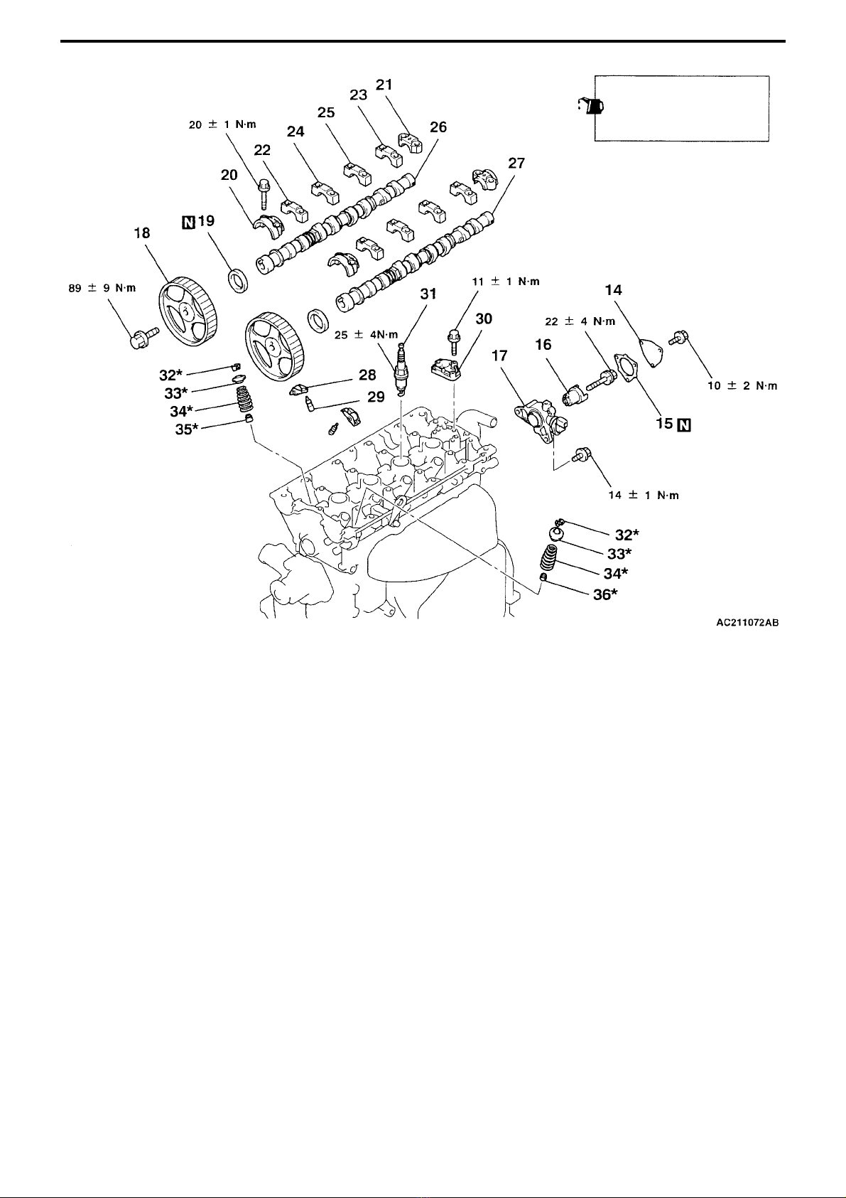
14. Camshaft osition sensor
su ort cover
15. Camshaft osition sensor
su ort cover gasket
16. Camshaft osition sensing
cylinder
17. Camshaft osition sensor
su ort
18. Camshaft s rocket
19. Camshaft oil seal
20. Camshaft bearing ca front
21. Camshaft bearing ca rear
22. Camshaft bearing ca No.2
23. Camshaft bearing ca No.5
24. Camshaft bearing ca No.3
25. Camshaft bearing ca No.4
26. Inlet camshaft
27. Exhaust camshaft
28. Rocker arm
29. Lash adjuster
30. Oil delivery body
31. S ark lug
32. Valve s ring retainer lock
33. Valve s ring retainer
34. Valve s ring
35. Inlet valve stem seal
36. Exhaust valve stem seal
When assembling, a ly
engine oil to all sliding
arts
J
I
B H
G
F
F
F
F
F
F
E
E
D
C C
B
A
A
4G6 ENGINE – CAMSHAFT, VALVE STEM SEAL
11A-4

4G6 ENGINE- CAMSHAFT , VALVE STEM SEAL 11A-5
Lubricant and seal application locations
<View of rocker cover lower surface>
Semi-dry sealant: Three Bond 1207D
<View from A>
Semi-dry sealant: Three
Bond 1207D
Engine oil
(Li art)
Rocker
Cover
Cylinder
head
Semi-dry sealant: Three Bond 1211
Semi-dry sealant: Three Bond 1207F
Ø 3mm
<View of cylinder head u er surface>
Semi-dry sealant: Three Bond 1207D
4G6 ENGINE – CAMSHAFT, VALVE STEM SEAL
11A-6
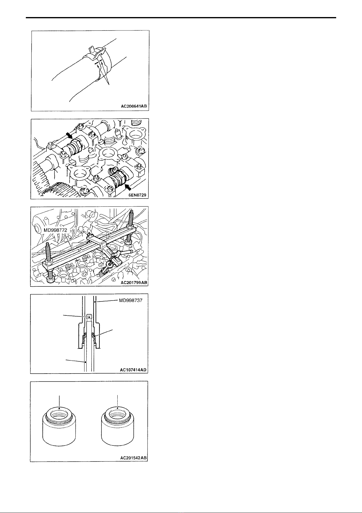
MAIN POINTS REGARDING REMOVAL
ADETACHING RADIATOR UPPER HOSE
Align the matching marks on radiator u er hose and hose clam , then
detach radiator u er hose.
BREMOVING CAMSHAFT SPROCKETS
Hold camshaft hexagonal art with a wrench, loosen mounting bolt, and
remove camshaft s rocket.
CREMOVING VALVE SPRING RETAINER LOCK
Com ress valve s ring using the s ecial valve s ring com ressor tool
(MD998772), and remove valve s ring retainer lock.
CAUTION
When removing the valve spring retainer lock, all cylinder pistons
should be in the top dead centre position. If pistons are not in the
top dead centre position, valves could fall into the cylinders.
ASSEMBLY - MAIN POINTS
AFitting e haust valve stem seals/inlet valve stem seals
1. A ly a small quantity of engine oil to valve stem seals
2. Place the valve stem into the guides, then insert a new valve stem
seal into the valve guide using the s ecial valve stem seal installer
(MD998737).
CAUTION
(1) Valve stem seals cannot be re-used.
(2) If valve stem seals are not fitted correctly, it could lead to oil
leaking down, so the special valve stem seal installer tool
(MD998737) should be used for fitting.
Note
Check the colours on the rubber arts to identify inlet valve stem seals
and exhaust valve stem seals.
Matching marks
Valve
Valve guide
Valve stem
seal
Colour of main
body: grey Colour of main body:
greenish grey colour
Inlet side Exhaust side
4G6 ENGINE- CAMSHAFT , VALVE STEM SEAL 11A-7
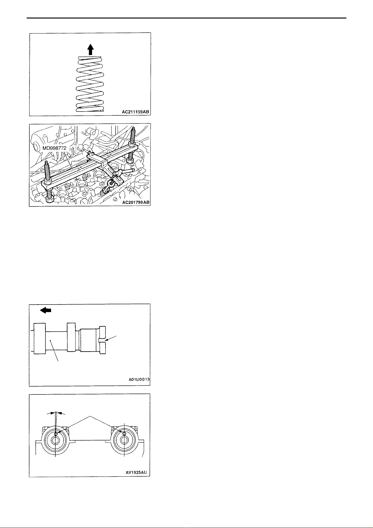
B FITTING VALVE SPRING
Fit so that the valve s ring small radius end is on the rocker arm side.
CFITTING VALVE SPRING RETAINER LOCK
Com ress the valve s ring using the same valve s ring com ressor tool
(MD998772) as the one used for removal and fit the valve s ring retainer
lock.
D FITTING LASH ADJUSTER
CAUTION
When re-using lash adjuster, without fail wash and check before fitting.
(Refer to Engine Worksho Manual)
EFITTING EXHAUST CAMSHAFT / INLET CAMSHAFT
1. Remove any sealant adhering to the cylinder head.
2. A ly engine oil to camshaft cams and journals.
3. Fit camshaft to cylinder head.
CAUTION
Do not get intake and e haust sides the wrong way round.
The e haust camshaft has a slit on the rear end.
F FITTING CAMSHAFT BEARING CAP No.4/ FITTING
CAMSHAFT BEARING CAP No.3/ FITTING CAMSHAFT BEARING
CAP No.5/ FITTING CAMSHAFT BEARING CAP No.2/ FITTING
CAMSHAFT BEARING CAP REAR/ FITTING CAMSHAFT
BEARING CAP FRONT
1. Set the camshaft dowel ins in the osition shown in the diagram.
Rocker arm side
Engine front direction
Slit
Exhaust camshaft
A rox. 3° Dowel ins
Intake side Exhaust side

4G6 ENGINE – CAMSHAFT, VALVE STEM SEAL
11A-8
2. The camshaft bearing ca s No.2~5 are the same sha e, so check the
identification marks before fitting in the direction shown in the diagram,
in order to avoid getting bearing ca number, and intake and exhaust
sides, mixed u .
Identification marks (stam ed on front and on bearing ca s No.2~5)
I: Intake side
E: Exhaust side
3. A ly sealant to the 6 ositions indicated in the diagram on the u er
surface of the cylinder head.
Semi-dry sealant: Three Bond 1207D
4. Fit camshaft bearing ca s so that front marks are in the direction
indicated.
5. Check the identification marks on the camshaft bearing ca fronts, so
that, as with bearing ca s No.2~5, there are no mistakes over intake
and exhaust sides.
6. Gradually tighten the bearing ca mounting bolts, 2~3 turns at a time, to
the s ecified torque.
Tightening torque: 20 ± 1 N·M
7. Check that the rocker arm is fitted correctly.
NB. Wi e away any traces of sealant squeezed out.
GFITTING CAMSHAFT OIL SEAL
1. A ly engine oil around the entire circumference of the oil seal li .
2. Insert oil seal using the s ecial camshaft oil seal installer tool
(MD998713), as shown in the diagram.
HAs when removing, hold the camshaft hexagonal art with a
wrench, then tighten the mounting bolts to the torque s ecified.
Tightening torque: 89 ± 9 N·M
Engine forward
direction
Bearing ca
No.2
Intake side
Exhaust side
marks
Engine forward direction
Engine forward
direction Front mark

4G6 ENGINE – CAMSHAFT, VALVE STEM SEAL 11A-9
IFITTING CAMSHAFT POSITION SENSOR SUPPORT
1. Remove any sealant on the camshaft osition sensor su ort.
2. A ly sealant to the camshaft osition sensor su ort flange, as
shown in the diagram, then fit to the cylinder head.
Semi-dry sealant: Three Bond 1207F
3. Tighten camshaft osition sensor su ort mounting bolts to the
torque s ecified.
Tightening torque: 14 ± 1 N·M
JFITTING CAMSHAFT POSITION SENSING CYLINDER
1. Set the exhaust camshaft dowel in in the osition shown in the
diagram (No.1 cylinder com ression to dead centre)
Note
It will turn slightly in a counter-clockwise direction, under ressure
from the exhaust valve s ring.
2. As shown in the diagram, fit the camshaft osition sensing cylinder
vain (small), so that it is a roximately 45° relative to the exhaust
camshaft dowel in.
3. Tighten the camshaft osition sensing cylinder mounting bolts to the
torque s ecified.
Tightening torque: 22 ± 4 N·M
KFITTING ROCKER COVER GASKET
1. Remove any sealant on the rocker cover gasket.
2. A ly sealant to 4 locations on the rocker cover lower surface, as
shown in the diagram.
Semi-dry sealant: Three Bond 1207D
3. Fit the rocker cover gasket to the rocker cover.
Vain (small)
A rox. 45° Dowel in
Vain (large)

4G6 ENGINE – CAMSHAFT, VALVE STEM SEAL
11A-10
LFITTING CAMSHAFT END SEALS
A ly sealant to the locations on the camshaft end seal, as shown in the
diagram, then fit to the cylinder head.
Semi-dry sealant: Three Bond 1211
MFITTING ROCKER COVER ASSY
1. A ly sealant to the 6 locations on the rocker cover gasket, as shown
in the diagram.
Semi-dry sealant: Three Bond 1207D
2. Fit the rocker cover ASSY to the cylinder head.
NCONNECTING RADIATOR UPPER HOSE
1. Insert radiator u er hose as far as the rotrusion on the water outlet
fitting.
2. Align the radiator u er hose and hose clam matching marks to fit the
radiator u er hose.
Cylinder head
Engine forward direction
Protrusion
Water outlet
fitting Matching mark

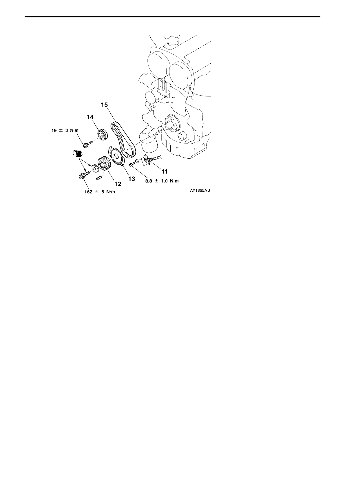
4G6 ENGINE – TIMING BELT, TIMING BELT B 11A-11
TIMING BELT and TIMING BELT B
Removal and Fitting
Caution
When Brembo brake callipers are used, there is concern over paint peeling off, so when doing servicing work, make
sure they are not scratched by other components and tools. Furthermore, if any brake fluid gets onto the calipers, it
should be wiped off immediately.
Jobs to do before removal and after fitting
• Removal and fitting of undercover (refer to Cha ter 51 Front Bum er)
• Removal and fitting of LH side cover
• Checking drive belt tension <only after fitting>
• Removal and fitting of crank shaft ulley
• Removal and fitting cross member bar
• Removal and fitting of front exhaust i e
Removal procedure
1. Timing belt front u er cover
2. Water um ulley
3. Idler ulley
4. Drive belt auto-tensioner
5. Timing belt front lower cover
• Timing belt tension adjustment
6. Timing belt
7. Tensioner ulley
8. Connecting earth cable
9. Auto-tensioner
10. Idler ulley
G
A F
E
D
4G6 ENGINE – TIMING BELT, TIMING BELT B
11A-12
11. Crank angle sensor
12. Crank shaft s rocket
13. Crank shaft sensing blade
• Timing belt B tension adjustment
14. Timing belt B tensioner
15. Timing belt B
B C
C
B
A
C A
Note
Carry out removal and fitting in accordance with existing
instructions
(Engine oil)


MPI (Multipoint Injection)
SECTION 13A
13A-1
CONTENTS
General..................................................................... 2
Special tools ............................................................3
Troubleshooting ......................................................5
Injectors ...................................................................100
Engine control registers and relays.......................102
MPI - GENERAL
13A-2
General
The following changes have been made to vehicles fitted with the 4G63-DOHC-T/C engine. Otherwise the system remains the
same.
• The engine ECU has been changed
• An immobiliser system has been fitted
• A lated metal delivery i e has been ado ted
• Fuel um relay mounting osition has been changed
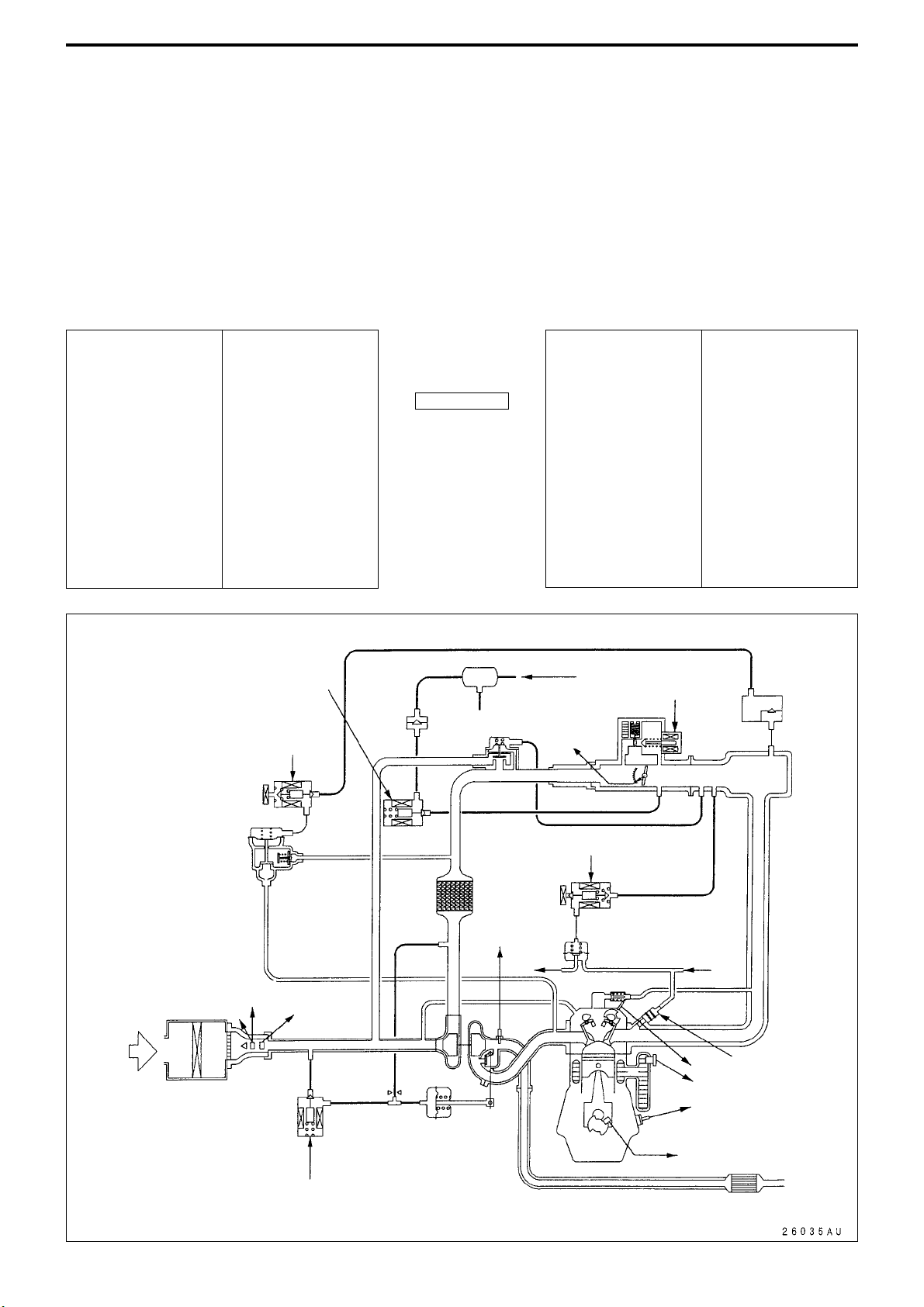
MPI SYSTEM DIAGRAM
Canister
✩2. ISC servo Vacuum
tank
By- ass
valve
Check
valve
✩5. Purge control
solenoid valve
✩6. Secondary air control
solenoid valve
Secondary air valve ✩3. Fuel ressure control solenoid valve
★1. O2
sensor Fuel
ressure
regulator
From
fuel
um
Intake
★2. Air flow sensor
★7. Barometric ressure sensor ★3. Intake
air tem .
sensor
✩4. Waste gate solenoid valve
Waste gate
actuator
Catalytic converter
★6. Crank angle sensor
★8. Water tem . sensor
✩1. Injector
From fuel tank
★4. Throttle
osition
sensor
Engine ECU
★1. O2 sensor
★2. Air flow sensor
★3. Intake air tem .
sensor
★4. Throttle osition
sensor
★5. Cam osition
sensor
★6. Crank angle
sensor
★7. Barometric
ressure sensor
★8. Water tem .
sensor
★9. Knock sensor
• Power su ly
• Ignition switch IG
• Ignition switch ST
• Vehicle s eed
sensor
• A/C switch
• A/C load signal
• Power steering
fluid ressure switch
• Alternator FR signal
• Intercooler water
s ray switch (auto)
• Intercooler water
s ray switch (manual)
✩1. Injector
✩2. ISC servo
✩3. Fuel ressure
control solenoid valve
✩4. Waste gate
solenoid valve
✩5. Purge control
solenoid valve
✩6. Secondary air
control solenoid valve
• Engine control relay
• Fuel um relay 2,3
• A/C relay
• Ignition coil
• Fan controller
• Condenser fan Relay
(HI)
• Condenser fan relay
(LO)
• Engine warning light
• Diagnosis out ut
• Alternator G terminal
• Intercooler water
s ray relay
• Intercooler water
s ray lam
• Tachometer
➩➩
★5. Cam osition sensor
★9. Knock sensor
To fuel
tank
Other manuals for Lancer Evolution-VIII
1
Table of contents


