Mitsubishi JT-S2AP-W-NE User manual

−1−
Read the manual thoroughly before beginning installation to ensure the unit is installed safely and correctly.
Local installation standards should be obeyed and installation should be performed by the dealer or a qualified professional.
The "INSTRUCTION MANUAL" is for the customer. Be sure to hand it to the customer.
INSTALLATION MANUAL For Dealers and Installers
Location of Model Name display
Location of power supply
voltage display
Single-phase 220 – 240V AC
INDEX
Safety Precautions …………………………………… 2
■Checking the installation environment ………… 3
Parts to be installed …………………………………… 4
■Main unit ………………………………………… 4
■Accessories ……………………………………… 5
■Required items …………………………………… 5
Use environment ……………………………………… 6
■Required space for installation ………………… 6
■Suitable walls …………………………………… 6
■Installation position ……………………………… 6
Installation procedure ………………………………… 7
■Fixing the installation panel …………………… 8
■Fixing the base…………………………………… 8
■Removing the terminal cover …………………… 9
■Wiring……………………………………………… 9
■Checking the setting …………………………… 11
■Attaching the front cover………………………… 12
Checking after installation …………………………… 13
■Removing the front cover after installation …… 13
Test Run ………………………………………………… 14
Instructions given to customer ……………………… 14
Hand dryer
1511876HB7401
GB
Unit colour -W (White) -S (Silver)
MODEL
JT-S2AP-W-NE
JT-S2AP-S-NE Heater Model
JT-S2A-W-NE Heater-less Model

−2−
Prohibited
Do not
disassemble
Prohibited
●
Do not install when the unit (power
cable) is electrified.
Doing so may result in electric shocks.
Important !
Follow
instructions
Safety Precautions
●
The dangers arising from improper handling and the extents of the dangers are classified and explained as shown
below.
Caution The following may lead to minor injuries or damage
to property if the unit is handled incorrectly.
Warning The following may lead to death or serious
personal injury if handled incorrectly.
●
Do not install in locations where they
may be leakages of combustible gas.
This may cause fires.
●
Do not install in locations where salt
damage may occur or where corrosive,
neutral or reductive gases are present.
This may cause malfunctions.
●
Do not scratch, damage, process,
excessively bend, pull, twist or bundle
the power cable.
Please also refrain from placing heavy
objects onto it or trapping it.
Failure to do so may damage the power
cable, causing fires or electric shocks.
●Do not attempt any disassembly or
modification of the unit that is not
expressly stated in this manual.
Doing so may result in fires, electric
shocks or injuries.
●Do not use in a hot location such as a
shower room, where condensation may
form on the unit or where water may
splash directly onto the unit.
This may cause electric shocks or
malfunctions.
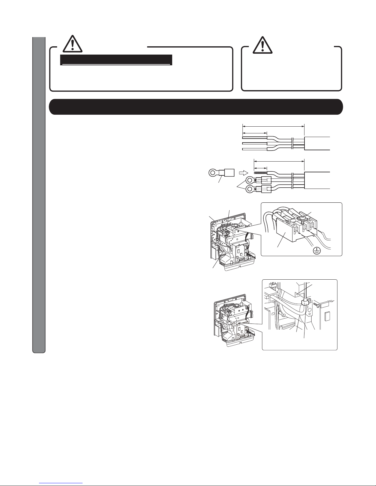
●Wiring work is to be done by a certified
electrical worker in accordance with
technical standards for electrical
equipment and int e rna l wiring
regulations.
Incorrect wiring work may cause electric
shocks or fires.
●Use single-phase 220 – 240V AC power.
Using the incor rect power supply may cause
fires, electric shocks or malfunctions.
●
Use exclusive wiring for the power
source.
Using this unit with other devices on a
branch socket may cause abnormal heat,
which may cause fires.
●Be sure to install a ground-fault circuit
interrupter.
Failure to do so may result in electric shocks.
●The unit shall be installed in accordance
with national wiring regulations.
●A means for disconnection must be
incorporated in the fixed wiring in
accordance with wiring rules.
Do not use
in the baths/
shower room
Important !
Follow
instructions
●
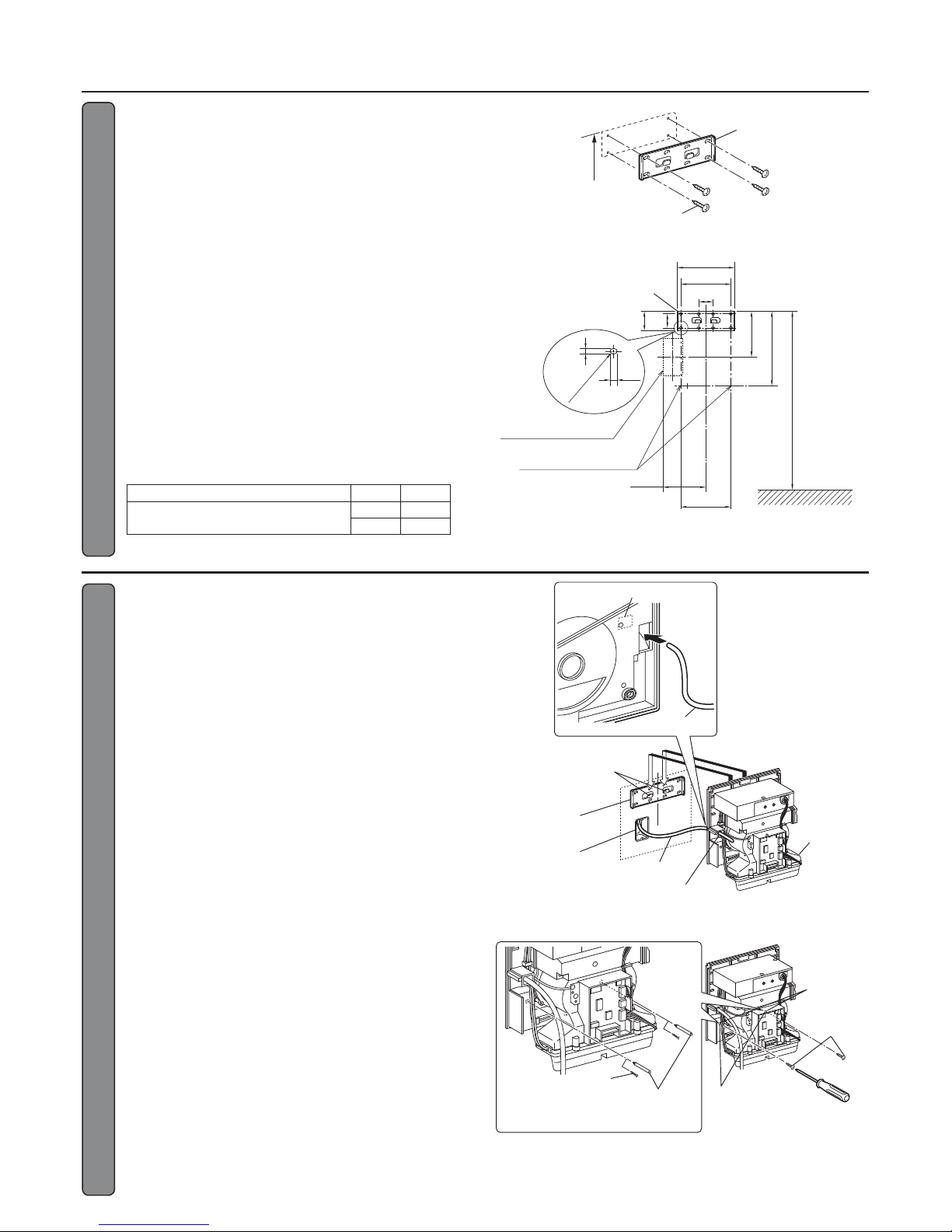
Install securely in a location strong
enough to support the weight of the
unit.
Injuries may be caused if the unit falls off
the wall.
●Wear gloves when installing the unit.
Not doing so may result in injuries.

−3−
Single-phase 220 – 240V AC power is used.
Using the incorrect power supply may cause fires, electric shocks or malfunctions.
Safety Precautions (continued)
Warning
■Checking the installation environment
Do not install the unit in the following types of locations.
(This may cause malfunctions.)
●Outdoors ●Locations where the temperature could be lower than 0C.
●Locations where there is a lot of dust. ●Locations where the temperature could be higher than 40C.
●Locations where there is a lot of condensation. ●Locations where salt damage may occur.
●Locations where the unit is in direct or strong sunlight (may cause the sensor to malfunction).
●In vehicles (including ships and airplanes)
●Locations where corrosive, neutral or reductive gasses are present.
(This may shorten the working life of the unit and/or cause malfunctions.)
●Near food or tableware ●Locations where the unit may come into direct contact with water.
●Kitchens
(Where there is a risk of water splashing.)
●Rooms that have a sterilisation basin, swimming pools and baths.

−4−
AIR SPEED
HEATER
ON OFF
HIGH STD
Air speed switch
Hand drying
area
Air inlet
Base
Front cover
Main unit
Power light
Settings
switches
Heater switch ※
Nozzle Sensor
TERMINAL
BLOCK
HOLE FOR
POWER CORD
(REAR)
69*4
91
77
260*7
160*5 2
21*6
231*2
149*3
290*1
140
100
250
<External dimensions>
■Front
Unit (mm)
●Refer to "Use environment". (Page 6)
■Rear
Power cord hole Main unit
NOTE
NOTE
Parts to be installed
■Main unit ※Shaded areas in the figure indicate antibacterial material (excluding outlet nozzle areas).
Front cover※
※The front cover of JT-S2AP is not antibacterial.
※JT-S2A does not have the heater switch.
●Prevent scratching on the front cover. Rust may form on the scratched area.
(JT-S2AP only)
●Please refer to "Heater ON/OFF setting" (Page 11) while turning the heater on/off.
●Please refer to "Air speed HIGH/STD setting" (Page 11) while adjusting the air speed.
Front cover
mounting screw
JT-S2A
*1: 292
*2: 233
*3: 151
*4: 71
*5: 162
*6: 23
*7: 262

−5−
■Accessories
■Required items
Screwdriver
Longer than 150mm
Pen
Screw anchor ……6 Wall reinforcement
※To mark position to insert metal
screw plugs in the wall.
※Use on concrete walls ※Reinforces walls made of
materials other than concrete.
■Prepare if required
※Not needed if the internal wiring is
complete.
Single wire for internal wiring
(Cable core: between 1.0mm² and 2.5mm²)
Parts to be installed (continued)
Mounting screws………………6
(5 ×30 Type 1 tapping screws)
Installation panel……………1 Cord clip mounting
screw (4 ×14)……… 1
Cord clip……… 1

−6−
Use environment
Top side
Right
side
Left side
Front
side Main unit Air inlet
Below side
54
149
A
209
40
120
140
140
40
160
10
7
R3.5
■Required space for installation
Caution Be sure to secure at least the
distances listed in the righthand
table from walls, flammable
(combustible) materials and so
on.
■Suitable walls
●When installing on a wall, select a wall with a flat and
even surface.
●When installing on a concrete wall, use commercially
available metal screw plugs.
●Reinforce any walls made with materials other than
concrete before installation.
■Installation position
●Refer to "Installation position guide" and "Installation
diagram" and install the unit in an easily accessible
position.
If it is installed at a low position, it may become wet
when the sink is being washed.
If water enters the unit, it may cause damage or
cause the acoustic materials to absorb water and
allow bacteria to grow.
●Do not install the main unit in locations such as
those near mirrors or walls.
This may lead to water drops flying to undesirable
areas during the drying of the hands.
●Do not install the main unit in locations such as
those near food or eating utensils.
This may lead to water drops flying to undesirable
areas during the drying of the hands.
●Avoid locations where people or doors might bump
into the unit.
Unit (mm)
Location Isolation
distance
Above 150
Left 100
Right 100
Front Open
Below Open
■Installation position guide
Installation panel
Guide from floor to
installation position
Men : 1355
Women: 1255
Unit (mm)
■Installation diagram
Installation panel
Installation hole in detail
Floor
surface
Mounting hole position
below the unit
Conduit box
Unit (mm)
Recommended A measurement during installation
Space below the unit A
When there are no objects below Men 1355
Women 1255
Unit (mm)

−7−
Warning
Single-phase 220 – 240V AC
power is used.
Using the incorrect power supply may cause fires, electric shocks or
malfunctions.
Caution
●
Do not install when the unit (power
cable) is electrified.
Doing so may result in electric
shocks.
For confirmation
□Single-phase 220 –240V AC power is being used (using the incorrect power supply may cause fires, electric
shocks or malfunctions).
□The ground fault circuit interrupter is attached (not attaching a ground fault circuit interrupter may result in
electric shocks).
□The power cable has a 1.0 mm2to 2.5 mm2core.
1
Confirm that the severing of wires
during fixed wiring work is in
accordance with wiring regulations.
●Follow the illustration on the right for the internal
wiring.
●The power cable forces out the main unit and
does not allow proper installation if the conduit
box is not used.
Power cable
Conduit box
About 250
Unit (mm)
Installation procedure
2
1 .Remove the front cover mounting
screw (1).
3. Remove the ground wire fixing screw
(1) from the base and remove the
front cover.
(JT-S2AP only)
2. Disengage the tab of the upper part
of the front cover.
①Attach the installation panel to the hook of
the main unit
②Hold down the installation panel and put your
hand on the claw hook to remove the front
cover
Front cover
Hook Installation panel Front cover
Claw hook
Main unit
Front cover
mounting screw
Front cover
Ta b
Base Base
Ground wire fixing
screw
Ground wire
Front cover
NOTE
●Prevent scratching on the front cover. Rust
may form on the scratched area.
(JT-S2AP only)

−8−
Installation procedure (continued)
4
1. Push the power cable for exclusive
wiring through the power cord hole
at the rear of the base.
2. Engage the base with the 2 hooks on
the installation panel.
3. Check that the 2 hooks on the front
cover are hooked in the base.
4. Check that the power cable is not
trapped behind the base.
5. While lightly pressing the base against
the wall, fix it with the accessory
mounting screws (5x30) (2).
●To install the unit on a concrete wall, before
fixing the base, embed commercially available
wall plugs into the wall with the following
procedure.
①Temporarily put the base on the installation
panel.
②Mark the position of the hole in the wall
through the mounting screw hole with a pen.
③Remove the base and embed the
commercially available wall plugs into the
marked positions.
●Reinforce any walls made with materials other
than concrete before installation.
Base
Power cable
Power cord hole
Power cord hole
Power cable
Conduit box
Installation
panel
Panel hooks
(2 locations)
Installation
hole
Mounting screws
(5 ×30)
(Accessories)
Plugging marks
on the wall
Plug positioning
Mounting screws (5 ×30)
(Accessories)
Mark the wall in
2 places
■Fixing the base
54
149
A
209
40
120
140
140
40
160
10
7
R3.5
Installation panel
Installation hole in detail
Floor
surface
Mounting hole position
below the unit
Conduit box
Unit (mm)
A
3
Fix the installation panel onto the wall
with 4 accessory mounting screws
(5 ×30).
●The "Installation position guide" illustrated on the
right is recommended.
●When installing on a wall, select a wall with a flat
and even surface.
●When installing on a concrete wall, use
commercially available metal screw plugs.
●Reinforce any walls made with materials other
than concrete before installation.
Installation panel
Mounting screws (5 ×30)
(Accessories)
■Installation position guide
Recommended A measurement during installation
Unit (mm)
Space below the unit A
When there are no objects below Men 1355
Women 1255
■Fixing the installation panel

−9−
6
Warning
Single-phase 220 – 240V AC power is used.
Using the incorrect power supply may cause fires, electric shocks
or malfunctions.
Caution
●Make sure that the main unit
does not fall as the base is not
attached to the wall with screws.
Injuries may be caused if the unit
falls off the wall.
Installation procedure (continued)
5
1. Remove the terminal cover mounting
screw (1) and remove the terminal
cover.
※Be careful not to lose the cord bushing.
Cord bushing
Base
Terminal cover
Screw
L
N
Connect the power cable to the
terminal block. (Ensure the polarity)
1. Remove 12mm (single wire) or 8mm
(stranded wire) of wire sheath from
the end.
2. Fix the power cable to the terminal block.
●When stranded wire is used for the power
cable, attach an insulated ring tongue terminal
using an appropriate tool.
●Proper torque is 1.2N·m
3. Check that the power cable is
securely fixed to the terminal block.
4. Use the cord clip mounting screw
hole to fix the power cable with the
accessory cord clip and mounting
screw (4 ×14).
●Proper torque is 1.2N·m
●Fix it where the external wire sheath of the
power cable is when it is fixed in the cord clip
mounting position.
Terminal block
Base
Power cable
Terminal block
Screw
Cord clip
mounting
screw hole
Power cable
Cord clip (Accessory)
Insulated ring tongue
terminal
■Single wire
80
12
73
8
■Stranded wire
Unit (mm)
JT-S2A
■Removing the terminal cover
■Wiring

−10 −
L
N
6
1. Remove 12mm (single wire) or 8mm
(stranded wire) of wire sheath from
the end.
2. Fix the power cable to the terminal block.
●When stranded wire is used for the power
cable, attach an insulated ring tongue terminal
using an appropriate tool.
●Proper torque is 1.2N·m
4. Check that the power cable and
ground wire are securely fixed to the
terminal block.
5. Fix the power cable and ground
wire using the accessory cord clip,
mounting screw (4x14) and cord clip
mounting screw hole.
●Proper torque is 1.2N·m
●Clip the sheathed portions of the power cable
and ground wire with the cord clip.
3.
Fix the ground wire to the terminal block.
●Proper torque is 1.2N·m
Terminal block
Base
Power cable
Terminal block
Screw
Cord clip
mounting
screw hole
Power cable
Cord clip (Accessory)
Insulated ring tongue
terminal
■Single wire
80
12
73
8
■Stranded wire
Unit (mm)
Installation procedure (continued)
Warning
Single-phase 220 – 240V AC power is used.
Using the incorrect power supply may cause fires, electric shocks
or malfunctions.
Caution
Make sure that the main unit
does not fall as the base is not
attached to the wall with screws.
Injuries may be caused if the unit
falls off the wall.
Connect the power cable to the terminal
block. (Ensure the polarity)
JT-S2AP

−11 −
AIR SPEED
HEATER
ON OFF
HIGH STD
7
1. Check the heater and air speed setting.
●To change the heater setting, refer to "Heater
ON/OFF setting".
●To change the air speed setting, refer to "Air
speed HIGH/STD* setting".
※STD:Standard
Air speed
switch
Heater
switch※
Installation procedure (continued)
※JT-S2A does not have the heater switch.
●Customer is not allowed to change the setting. The installer should change the initial setting if necessary.
●The initial setting is as shown in the table below.
①Turn the heater switch "ON".
※The heater may not operate during continued use as there is
the danger of scalding when the temperature of the warm air
rises.
The air may not feel warm when the room temperature is low
(20°C or below).
AIR SPEED
HEATER
ON OFF
HIGH STD
Heater switch
■Heater ON/OFF setting
■Air speed HIGH/STD setting
①Set the air speed switch to "HIGH" or "STD".
●Refer to "Guide of air speed setting and drying time".
AIR SPEED
HEATER
ON OFF
HIGH STD
Air speed switch
■Guide of air speed setting and drying time
Settings Drying times guide ※Noise Use
HIGH (approx.) 9 – 12 seconds (approx.)
60 – 62dB When drying quickly
STD (approx.) 14 – 16 seconds (approx.)
58 – 59dB
When keeping the noise level
down during operation
※Drying times are based on Mitsubishi measurements. (50mg of water per hand)
Initial setting
Type Heater Air speed
JT-S2AP ON HIGH
JT-S2A ー※HIGH
※JT-S2A does not have the heater switch.
■Checking the setting
※STD:Standard

−12 −
8
9
1. Pass the power cable through
the cord bushing and fix it to the
base again with the terminal cover
mounting screw.
2. Check that the power cable and wires
are not pinched anywhere.
1. Fix the ground wire removed in
step 3to the base again.
(JT-S2AP only)
2. Attach the front cover to the base.
①Fit the front cover to the bottom of the
base.
②Align the plate inside the front cover with
the slit on the right of the base and mount
the front cover.
●Do not push the front cover unless the plate
inside it is aligned with the slit on the right of
the base.
Doing so may damage the product.
3. Fix the front cover with the front
cover mounting screw (1).
●The screw hole is on the bottom.
4. Check that the tab of the front cover
is securely engaged.
Base
Screw
Terminal
cover
Cord bushing
Installation procedure (continued)
①
②Slit
Ground wire
Front cover
Ground wire fixing screw
Front cover mounting
screw
Plate
Front cover
Front cover
Base
Ta b
■Attaching the front cover
NOTE
●Prevent scratching on the front cover. Rust
may form on the scratched area.
(JT-S2AP only)

−13 −
1
Remove the front cover mounting screw (1) on
the bottom of the main unit.
2
Insert a thin stick or the like into near the tab of
the upper part of the front cover and disengage
the tab.
3
Remove the ground wire fixing screw (1) from
the base and remove the front cover.
(JT-S2AP only)
4
Perform checking after installation.
●Check the "Points to be checked".
5
After inspection, attach the front cover in the
reverse order.
Ta b
Front
cover
Base
Front cover
mounting screw
Front cover
Ground wire
Front cover
Ground wire fixing screw
①
②
■Removing the front cover after installation
Checking after installation
●When finishing the installation work, check the items in the table below again.
Be sure to solve a problem if any.
(Otherwise the expected performance and safety cannot be ensured.)
■Points to be checked
Item Description Check
1 Wiring
Check that the wiring conforms to the extension rules of the technical standards for electrical
equipment.
(If not, fire may occur.)
2 Fixation of the main unit Check that the main unit is securely fixed on a strong surface.
(If not, personal injury may occur or the product may fail.)
3 Power supply voltage Check that the voltage is 220 - 240 VAC.
(If not, the product may fail.)
4 Grounding Check that JT-S2AP is securely grounded.
(If not, the product may malfunction or fail.)
5 Setting
Check that the setting is correct.
Customer is not allowed to change the setting. Be sure to check the operation if the initial
setting is changed.
The initial setting is heater "ON" and air speed "HIGH".
NOTE
●Prevent scratching on the front cover. Rust may form on the
scratched area.
(JT-S2AP only)

−14 −
Step What to check for Check
1Check the power supply
voltage
Is the proper power being used?
( Single-phase 220 – 240V AC )
Incorrect power supply may cause malfunctions or low
wind power.
2Turn the ground-fault circuit
interrupter "ON" Are any lights in the display on?
3Insert your hands to check if air is
being blow.
Is the air blowing?
Is warm air blowing? (JT-S2AP only)
( Even if the heater switch is "ON", the heater may not operate
if it is used continually.)
※As the heater is a simple heater, the air may not feel so
warm if the room temperature is low (20C or below).
4Is the unit mounted securely without any vibration or abnormal
noises?
Test Run
●Explain how to use the jet dryer to customer according to the instruction manual. Especially request customer to
observe the important safety instructions in "Safety Precautions".
●Provide customer with this installation manual after completing installation.
●If user is not there, give instructions to caretaker.
Instructions given to customer

−15 −
HEAD OFFICE: TOKYO BLDG., 2-7-3, MARUNOUCHI, CHIYODA-KU, TOKYO 100-8310, JAPAN
AUTHORIZED REPRESENTATIVE IN EU:
MITSUBISHI ELECTRIC EUROPE B.V.
HARMAN HOUSE, 1 GEORGE STREET, UXBRIDGE, MIDDLESEX UB8 1QQ, U.K.

English
Your MITSUBISHI ELECTRIC product is designed and
manufactured with high quality materials and components which
can be recycled and/or reused.
This symbol means that electrical and electronic equipment,
batteries and accumulators, at their end-of-life, should be
disposed of separately from your household waste.
If a chemical symbol is printed beneath the symbol shown
above, this chemical symbol means that the battery or
accumulator contains a heavy metal at a certain concentration.
This will be indicated as follows:
Hg: mercury (0,0005%), Cd: cadmium (0,002%),
Pb: lead (0,004%)
In the European Union there are separate collection systems
for used electrical and electronic products, batteries and
accumulators.
Please, dispose of this equipment, batteries and accumulators
correctly at your local community waste collection/recycling
centre.
Please, help us to conserve the environment we live in!
Deutsch
Ihr MITSUBISHI ELECTRIC-Produkt wurde unter Einsatz
von qualitativ hochwertigen Materialien und Komponenten
konstruiert und gefertigt, die für Recycling und/oder
Wiederverwendung geeignet sind.
Dieses Symbol bedeutet, dass elektrische und elektronische
Geräte sowie Batterien und Akkus am Ende ihrer
Nutzungsdauer von Hausmüll getrennt zu entsorgen sind.
Wenn ein chemisches Symbol unterhalb des oben abgebildeten
Symbols erscheint, bedeutet dies, dass die Batterie bzw. der
Akku ein Schwermetall in einer bestimmten Konzentration
enthält. Dies wird wie folgt angegeben:
Hg: Quecksilber (0,0005 %), Cd: Cadmium (0,002 %),
Pb: Blei (0,004 %)
In der Europäischen Union gibt es unterschiedliche
Sammelsysteme für gebrauchte Elektrik- und Elektronikgeräte
einerseits sowie Batterien und Akkus andererseits.
Bitte entsorgen Sie dieses Gerät, Batterien und Akkus
vorschriftsmäßig bei Ihrer kommunalen Sammelstelle oder im
örtlichen Recycling-Zentrum.
Bitte helfen Sie uns, die Umwelt zu erhalten, in der wir leben!
Italiano
Questo prodotto MITSUBISHI ELECTRIC è stato progettato
e fabbricato con materiali e componenti di alta qualità, che
possono essere riciclati e/o riutilizzati.
Questo simbolo significa che i prodotti elettrici ed elettronici, le
batterie e gli accumulatori, devono essere smaltiti separatamente
dai rifiuti casalinghi alla fine della loro vita di servizio.
Se sotto il simbolo mostrato sopra è stampato un simbolo chimico,
il simbolo chimico significa che la batteria o l’accumulatore
contiene un metallo pesante con una certa concentrazione. Ciò
viene indicato come segue:
Hg: mercurio (0,0005%), Cd: cadmio (0,002%),
Pb: piombo (0,004%)
Nell’Unione Europea ci sono sistemi di raccolta differenziata per i
prodotti elettrici ed elettronici, le batterie e gli accumulatori usati.
Per disfarsi di questo prodotto, delle batterie e degli accumulatori,
portarli al centro locale di raccolta/riciclaggio dei rifiuti.
Aiutateci a conservare l’ambiente in cui viviamo!
Français
Votre produit Mitsubishi Electric est conçu et fabriqué avec des
matériels et des composants de qualité supérieure qui peuvent être
recyclés et/ou réutilisés.
Ce symbole signifie que les équipements électriques et électroniques,
les batteries et les accumulateurs, à la fin de leur durée de service,
doivent être éliminés séparément des ordures ménagères.
Si un symbole chimique est imprimé sous le symbole illustré ci-dessus,
il signifie que la batterie ou l’accumulateur contient une certaine
concentration de métal lourd. Elle sera indiquée comme suit :
Hg : mercure (0,0005%), Cd : cadmium (0,002%),
Pb : plomb (0,004%)
Dans l’Union Européenne, il existe des systèmes sélectifs de
collecte pour les produits électriques et électroniques, les batteries
et les accumulateurs usagés.
Nous vous prions donc de confier cet équipement, ces batteries et
ces accumulateurs à votre centre local de collecte/recyclage.
Aidez-nous à conserver l’environnement dans lequel nous vivons !
Les machines ou appareils électriques et électroniques contiennent
souvent des matières qui, si elles sont traitées ou éliminées
de manière inappropriée, peuvent s’avérer potentiellement
dangereuses pour la santé humaine et pour l’environnement.
Cependant, ces matières sont nécessaires au bon fonctionnement de
votre appareil ou de votre machine.
Pour cette raison, il vous est demandé de ne pas vous débarrasser de
votre appareil ou machine usagé avec vos ordures ménagères.
Español
Su producto MITSUBISHI ELECTRIC está diseñado y fabricado
con materiales y componentes de alta calidad que pueden ser
reciclados y/o reutilizados.
Este símbolo significa que el aparato eléctrico y electrónico, las pilas,
baterías y los acumuladores, al final de su ciclo de vida, se deben
tirar separadamente del resto de sus residuos domésticos.
Si hay un símbolo químico impreso debajo del símbolo mostrado
arriba, este símbolo químico significa que la pila, batería o el
acumulador contienen un metal pesado con cierta concentración.
Esto se indicará de la forma siguiente:
Hg: mercurio (0,0005%), Cd: cadmio (0,002%),
Pb: plomo (0,004%)
En la Unión Europea existen sistemas de recogida específicos para
productos eléctricos y electrónicos, pilas, baterías y acumuladores
usados.
Por favor, deposite los aparatos mencionados, las pilas, baterías y
acumuladores en el centro de recogida/reciclado de residuos de su
lugar de residencia local cuando quiera tirarlos.
i Ayúdenos a conservar el medio ambiente!
Português
O seu produto MITSUBISHI ELECTRIC foi concebido e produzido
com materiais e componentes de alta qualidade que podem ser
reciclados e/ou reutilizados.
Este símbolo significa que o equipamento eléctrico e electrónico,
as baterias e os acumuladores, no final da sua vida útil, devem ser
deitados fora separadamente do lixo doméstico.
Se houver um símbolo químico impresso por baixo do símbolo
mostrado acima, o símbolo químico indica que a bateria
ou acumulador contém metais pesados numa determinada
concentração. Isto aparecerá indicado da maneira seguinte:
Hg: mercúrio (0,0005%), Cd: cádmio (0,002%),
Pb: chumbo (0,004%)
Na União Europeia existem sistemas de recolha separados para
produtos eléctricos e electrónicos, baterias e acumuladores usados.
Por favor, entregue este equipamento, as baterias e os
acumuladores correctamente, no seu ponto local de recolha/
reciclagem.
Por favor, ajude-nos a conservar o ambiente em que vivemos!
Information on Disposal
Note: This symbol mark is for EU countries only.
This symbol mark is according to the directive 2012/19/EU Article 14 Information for users and Annex IX,
and/or to the directive 2006/66/EC Article 20 Information for end-users and Annex II.

Svenska
Denna produkt från MITSUBISHI ELECTRIC är designad och
tillverkad av material och komponenter med hög kvalitet som
kan återvinnas och/eller återanvändas.
Denna symbol betyder att förbrukade elektriska och elektroniska
produkter, batterier och ackumulatorer skall sorteras och
hanteras separat från hushållsavfall.
Om det finns en kemisk beteckning tryckt under ovanstående
symbol betyder det att batteriet eller ackumulatorn innehåller en
tungmetall med en viss koncentration. Detta anges på följande
sätt:Hg: kvicksilver (0,0005%), Cd: kadmium (0,002%),
Pb: bly (0,004%)
Inom den Europeiska Unionen finns det separata
insamlingssystem för begagnade elektriska och elektroniska
produkter, batterier och ackumulatorer.
Var vänlig lämna denna produkt, batterier och ackumulatorer
hos din lokala mottagningsstation för avfall och återvinning.
Var snäll och hjälp oss att bevara miljön vi lever i!
Dansk
Dit produkt fra MITSUBISHI ELECTRIC er designet og fremstillet
med kvalitetsmaterialer og komponenter, der kan genindvindes og/
eller genbruges.
Dette symbol viser, at elektrisk eller elektronisk udstyr, batterier
og akkumulatorer ikke må bortskaffes sammen med almindeligt
husholdningsaffald efter endt levetid.
Hvis der er trykt et kemisk symbol under symbolet ovenfor,
betyder det, at batteriet eller akkumulatoren indeholder en bestemt
koncentration af et tungmetal. Dette angives som følger:
Hg: kviksølv (0,0005 %), Cd: cadmium (0,002 %),
Pb: bly (0,004 %)
I EU er der særlige indsamlingsordninger for brugte elektriske og
elektroniske produkter, batterier og akkumulatorer.
Bortskaf udstyret, batterier og akkumulatorer korrekt på en lokal
affalds-/genbrugsplads.
Hjælp os med at bevare det miljø, vi lever i!
Norsk
For norske brukere:
Dette produktet fra MITSUBISHI ELECTRIC er konstruert og
produsert med materialer og komponenter av høy kvalitet, som
kan resirkuleres og/eller brukes om igjen.
Dette symbolet betyr at elektrisk og elektronisk utstyr,
batterier og akkumulatorer, ikke bør kasseres sammen med
husholdningsavfallet når de har nådd slutten av sin levetid.
Hvis det er trykt et kjemisk symbol under det symbolet som
er vist over, betyr det kjemiske symbolet at batteriet eller
akkumulatoren inneholder et tungmetall i en viss konsentrasjon.
Dette vil vises som følger:
Hg: kvikksølv (0,0005 %), Cd: kadmium (0,002 %),
Pb: bly (0,004 %)
I Norge finnes det egne innsamlingssystemer for brukte
elektriske og elektroniske produkter, batterier og akkumulatorer.
Kasser dette utstyret, batteriene og akkumulatorene ved den
lokale gjenbruks- eller resirkuleringsstasjonen.
Hjelp oss å bevare det miljøet vi lever i!
Suomi
Tämä MITSUBISHI ELECTRIC -tuote on suunniteltu ja valmistettu
korkealuokkaisista materiaaleista ja/tai osista, jotka voidaan
kierrättää ja käyttää uudelleen.
Tämä symboli tarkoittaa, että sähkö- ja elektroniikkalaitteet,
paristot ja akut täytyy niiden käyttöiän jälkeen hävittää erillään
talousjätteistä.
Jos yllä olevan symbolin alapuolelle on painettu kemiallinen
symboli, se tarkoittaa, että paristolla tai akulla on tietty
raskasmetallipitoisuus. Se ilmoitetaan seuraavasti:
Hg: elohopea (0,0005 %), Cd: kadmium (0,002 %),
Pb: lyijy (0,004 %)
Käytetyillä sähkö- ja elektroniikkalaitteilla, paristoilla ja akuilla on
Euroopan Yhteisössä omat keräysjärjestelmänsä.
Toimita tämä laite, paristot ja akut paikalliseen jätehuolto-/
kierrätyskeskukseen.
Auta meitä suojelemaan ympäristöä, jossa elämme!
Nederlands
Mitsubishi Electric producten zijn ontwikkeld en gefabriceerd
uit eerste kwaliteit materialen. De onderdelen kunnen worden
gerecycled en/of worden hergebruikt.
Het symbool betekent dat de elektrische en elektronische
onderdelen, batterijen en accu’s op het einde van de
gebruiksduur gescheiden van het huishoudelijk afval moeten
worden ingezameld. Wanneer er onder het bovenstaande
symbool een chemisch symbool staat gedrukt, betekent dit dat
de batterij of accu zware metalen in een bepaalde concentratie
bevat. Dit wordt als volgt aangeduid:
Hg: kwik (0,0005%), Cd: cadmium (0,002%),
Pb: lood (0,004%)
In de Europese Unie worden elektrische en elektronische
producten, batterijen en accu’s afzonderlijk ingezameld.
Breng deze apparatuur, batterijen en accu’s dan naar het
gemeentelijke afvalinzamelingspunt.
Help ons mee het milieu te beschermen!
ǽȝȝșȟțȜȑ
ȉȠ ʌȡȠȧȩȞ MITSUBISHI ELECTRIC ʌȠȣ įȚĮșȑIJİIJİ İȓȞĮȚ
ıȤİįȚĮıȝȑȞȠ țĮȚ țĮIJĮıțİȣĮıȝȑȞȠ Įʌȩ ȣȜȚțȐ țĮȚ İȟĮȡIJȒȝĮIJĮ
ȣȥȘȜȒȢ ʌȠȚȩIJȘIJĮȢ, IJĮ ȠʌȠȓĮ ȝʌȠȡȠȪȞ ȞĮ ĮȞĮțȣțȜȦșȠȪȞ Ȓ/țĮȚ
ȞĮ ȤȡȘıȚȝȠʌȠȚȘșȠȪȞ ȟĮȞȐ.
ȉȠ ıȪȝȕȠȜȠ ĮȣIJȩ ıȘȝĮȓȞİȚ ȩIJȚ ȠȘȜİțIJȡȚțȩȢ țĮȚ ȘȜİțIJȡȠȞȚțȩȢ
İȟȠʌȜȚıȝȩȢ, ȠȚ ȝʌĮIJĮȡȓİȢ țĮȚ ȠȚ ıȣııȦȡİȣIJȑȢ, ıIJȠ IJȑȜȠȢ IJȘȢ
įȚȐȡțİȚĮȢ ȗȦȒȢ IJȠȣȢ, șĮ ʌȡȑʌİȚ ȞĮ ĮʌȠȡȡȚijIJȠȪȞ ȟİȤȦȡȚıIJȐ Įʌȩ
IJĮ ȣʌȩȜȠȚʌĮ ȠȚțȚĮțȐ ĮʌȠȡȡȓȝȝĮIJȐ ıĮȢ.
ǹȞ ȑȤİȚ İțIJȣʌȦșİȓ ȑȞĮ ȤȘȝȚțȩ ıȪȝȕȠȜȠ țȐIJȦ Įʌȩ IJȠ ıȪȝȕȠȜȠ
ʌȠȣ ĮʌİȚțȠȞȓȗİIJĮȚ ĮȞȦIJȑȡȦ, ĮȣIJȩ IJȠ ȤȘȝȚțȩ ıȪȝȕȠȜȠ ıȘȝĮȓȞİȚ
ȩIJȚ ȘȝʌĮIJĮȡȓĮ ȒȠıȣııȦȡİȣIJȒȢ ʌİȡȚȑȤİȚ ȑȞĮ ȕĮȡȪ ȝȑIJĮȜȜȠ ıİ
ȠȡȚıȝȑȞȘ ıȣȖțȑȞIJȡȦıȘ. ǹȣIJȩ șĮ ȣʌȠįİȚțȞȪİIJĮȚ ȦȢ ĮțȠȜȠȪșȦȢ:
Hg: ȣįȡȐȡȖȣȡȠȢ (0,0005%), Cd: țȐįȝȚȠ (0,002%),
Pb: ȝȩȜȣȕįȠȢ (0,004%)
ȈIJȘȞ ǼȣȡȦʌĮȧțȒ DzȞȦıȘ ȣʌȐȡȤȠȣȞ ȟİȤȦȡȚıIJȐ ıȣıIJȒȝĮIJĮ
ıȣȜȜȠȖȒȢ ȖȚĮ IJĮ ȤȡȘıȚȝȠʌȠȚȘȝȑȞĮ ȘȜİțIJȡȚțȐ țĮȚ ȘȜİțIJȡȠȞȚțȐ
ʌȡȠȧȩȞIJĮ, IJȚȢ ȝʌĮIJĮȡȓİȢ țĮȚ IJȠȣȢ ıȣııȦȡİȣIJȑȢ.
ȆĮȡĮțĮȜȠȪȝİ įȚĮșȑıIJİ ĮȣIJȩȞ IJȠȞ İȟȠʌȜȚıȝȩ, IJȚȢ ȝʌĮIJĮȡȓİȢ țĮȚ
IJȠȣȢ ıȣııȦȡİȣIJȑȢ ıIJȠ IJȠʌȚțȩ ıĮȢ țȠȚȞȠIJȚțȩ țȑȞIJȡȠ ıȣȜȜȠȖȒȢ/
ĮȞĮțȪțȜȦıȘȢ ĮʌȠȡȡȚȝȝȐIJȦȞ.
ǺȠȘșȒıIJİ ȝĮȢ ȞĮ ʌȡȠıIJĮIJİȪıȠȣȝİ IJȠ ʌİȡȚȕȐȜȜȠȞ ıIJȠ ȠʌȠȓȠ
ȗȠȪȝİ!
1509874HK5202

Technical Document of Fan Efficienc
y
Model Name JT-S2AP, JT-S2A
Overall Efficiency 54.0%
Measurement Category C
Efficiency Category Static
Efficiency Grade 61
VSD A variable speed drive is integrated within the fan
Year of Manufacture 2015
Manufacturer
Mitsubishi Electric Corporation
Head Office: Tokyo Bldg., 2-7-3, Marunouchi, Chiyoda-ku, Tokyo 100-8310, Japan
Authorised representative in EU:
Mitsubishi Electric Europe B.V.: 1 George Street, Harman House, Uxbridge, Middlesex, UB81QQ
Commercial registration no. 33279602
Motor Power Input (kW) 0.67
Flow Rate
(
m3/s
)
0.02
Pressure (Pa) 16,520
Rotations per Minute 34,847
Specific Ratio 1.0
Information relevant for facilitating
disassembly, recycling or disposal at end-of-
life
Your product should be disposed of separately from household waste in line with local laws and regulations.
When this product reaches its end of life, dispose of it at your local waste collection point/recycling centre.
The separate collection and recycling of your product at the time of disposal will help conserve natural resources and
ensure that it is recycled in a manner that protects human health and the environment.
For more information for WEEE recyclers please contact us at http://www.mitsubishielectric.eu/contact_us_form
Information relevant to minimise impact on
the environment and ensure optimal life
expectancy as regards installation, use and
maintenance of the fan
Remove dust on air filter around once a week.
Description of additional items used when
determining the fan energy efficiency The optimistic fan efficiency is measured in the composition of fan, motor and fan casing only.
876HD1701

Eteint
Clignote (toutes les 0,4 sec.)
Allumé
CHECK SHEET
ż
: Lit
ۼ
: Blinking (every 0.4 sec)
Ɣ
: Unlit
· ³¡¦·»ª·µ¸´
Fusibles à intensité du circuit de commande
FUSE1.......250 V - 20 A
FUSE2.......250 V - 5 A
(JT-S2AP ONLY)
FUSE3.......250 V - 6.3 A
THERMAL FUSE1 THERMAL FUSE2 (JT-S2AP ONLY)
1511876HD1601
Current fuse in control circuit
¢dªr¦³ÂŢΦª»¤
控制電路內的電流保險絲
ɉɥɚɜɤɚɹ ɜɫɬɚɜɤɚ ɩɨ ɬɨɤɭ ɜɰɟɩɢ ɭɩɪɚɜɥɟɧɢɹ
Malfunction location quick reference chart
(The display LED light is displayed in the blinking location)
熄滅
點亮
閃爍 (每0.4秒一次)
ɇɟ ɝɨɪɢɬ
Ƚɨɪɢɬ
Ɇɢɝɚɟɬ (ɤɚɠɞɵɟ 0,4 ɫ)
Température de fusion du fusible thermique
Ɍɟɦɩɟɪɚɬɭɪɚ ɩɥɚɜɥɟɧɢɹ ɬɟɪɦɨɩɪɟɞɨɯɪɚɧɢɬɟɥɹ
Fusible thermique dans le moteur Fusible thermique du réchauffeur
Thermal fuse in heater
Ɍɟɪɦɨɩɪɟɞɨɯɪɚɧɢɬɟɥɶ ɧɚɝɪɟɜɚɬɟɥɹ
Thermal fuse in motor
Ɍɟɪɦɨɩɪɟɞɨɯɪɚɧɢɬɟɥɶ ɞɜɢɝɚɬɟɥɹ
.....94°C
.....94°C
Thermal fuse fusion temperature
°»®£¼¤·®¨°¤¨³¨µ¥°Á°¦rä¢dªr
Á°¦rä¢dªrĤ°Á°¦r Á°¦rä¢dªrÄÁ¦ºÉ°¶ªµ¤¦o°
溫度保險絲熔斷溫度
馬達溫度保險絲 加熱器溫度保險絲
Ex: “Motor abnormality 1” blinks 3 times
<Blinking cycle>
0.4 sec 2.4 sec
Blinking…(predetermined number of blinks)
Blinks for 0.4 seconds
Light turns off for 0.4 seconds
Light turns off
(Light turns off
for 2.4 seconds)
<Cycle de clignotement>
Clignotement... (nombre prédéterminé de clignotements)
Lumière allumée pendant 0,4 secondes
Lumière éteinte pendant 0,4 secondes
Lumière éteinte
(Lumière éteinte
pendant 2,4 secondes)
¦°µ¦³¡¦·!
³¡¦·…¶ª¦´Ê¸É³¡¦·¸É¶®Åª¨oªn®µo
³¡¦·Á}Áª¨µª·µ¸
Å¢´Á}Áª¨µª·µ¸
Å¢´
Å¢´Á}Áª¨µª·µ¸
<ɐɢɤɥ ɦɢɝɚɧɢɹ>
Ɇɢɝɚɟɬ… (ɡɚɪɚɧɟɟ ɡɚɞɚɧɧɨɟ ɤɨɥɢɱɟɫɬɜɨ ɪɚɡ)
Ɇɢɝɚɟɬ 0,4 ɫɟɤɭɧɞɵ
Ƚɚɫɧɟɬ ɧɚ 0,4 ɫɟɤɭɧɞɵ
Ƚɚɫɧɟɬ
(Ƚɚɫɧɟɬ ɧɚ
2,4 ɫɟɤɭɧɞɵ)
Ex. : « Anomalie moteur 1 » clignote 3 fois
0,4 s 2,4 s
´ª°¥nµvµ¦¶µ··°¤°Á°¦rw³¡¦·¦´Ê
ª·µ¸ ª·µ¸
ɇɚɩɪ.: «ɇɚɪɭɲɟɧɢɟ ɜɪɚɛɨɬɟ ɞɜɢɝɚɬɟɥɹ 1» Ɇɢɝɚɟɬ 3 ɪɚɡɚ
0,4 ɫ2,4 ɫ
FICHE DE CONTRÔLE Á°µ¦¦µ¥µ¦·É¸Éo°¦ª°
檢視表單
ɄɈɇɌɊɈɅɖɇɕɃ ɅɂɋɌ

1511876HD1601
Description POWER (LED1) Main cause of error
Normal
When normal –
Tamper prevention 30-second continuous operation (automatic return)
Abnormal
Ɣ
ż
Power-supply detection abnormality 2 blinks Power-supply noise (automatic return)
Motor abnormality 1 3 blinks Motor: lock/connector detached
Motor abnormality 2 4 blinks Motor: brush life limit/brush abnormality
Power board temperature abnormality 5 blinks Power board: high-temperature/low-temperature(automatic return)
Main board temperature abnormality 6 blinks Main board: high-temperature/low-temperature(automatic return)
Microcomputer abnormality 7 blinks Microcomputer abnormality (main board)
Power-supply OFF/fuse melting Power-supply OFF, electric current fuse and temperature fuse melting
Description
ALIMENTATION (LED1)
Cause principale de l’erreur
Normal
En situation normale –
Prévention des altérations Fonctionnement continu pendant 30 secondes (retour automatique)
Anormal
Ɣ
ż
Anomalie de détection de l’alimentation électrique 2 clignotements Bruit de l’alimentation électrique
(retour automatique)
Anomalie moteur 1 3 clignotements Moteur : verrou/connecteur détaché
Anomalie moteur 2 4 clignotements Moteur : limite de durée de vie des balais/anomalie des balais
Anomalie de la température de la carte d’alimentation 5 clignotements Carte d’alimentation : température élevée/basse température
(retour automatique)
Anomalie de température de la carte principale 6 clignotements Carte principale : température élevée/basse température
(retour automatique)
Anomalie micro-ordinateur 7 clignotements Anomalie micro-ordinateur (carte principale)
Alimentation électrique arrêtée/fusible fondu
Alimentation électrique arrêtée, fusible de courant électrique et fusible de température fondus
¶°·µ¥ Ádd/(' µÁ®»®¨´¸É¶Ä®oÁ·o°·¡¨µ
·
Á¤ºÉ°°¥¼nÄ£µª³· –
µ¦j°´µ¦Â¦Âµ¦¶µ µ¦Äoµ°¥nµn°ÁºÉ°ª·µ¸ ¨´¤µ¶µÄ®¤nÃ¥°´Ã¤´·
··
Ɣ
ż
µ¦¦ª´µ¦¶µ··°Â®¨nnµ¥Å¢ ³¡¦·¦´Ê´µ¦ª°Â®¨nnµ¥Å¢ ¨´¤µ¶µÄ®¤nÃ¥°´Ã¤´·
µ¦¶µ··°¤°Á°¦r ³¡¦·¦´Ê ¤°Á°¦r¨È°´Êªn°¼¨°°
µ¦¶µ··°¤°Á°¦r ³¡¦·¦´Ê ¤°Á°¦r¹¸¶´°µ¥»µ¦Äoµ°Â¦µ¦¶µ··°Â¦
°»®£¼¤·°ÂÅ¢·· ³¡¦·¦´Ê ÂÅ¢°»®£¼¤·¼°»®£¼¤·É¶ ¨´¤µ¶µÄ®¤nÃ¥°´Ã¤´·
°»®£¼¤·°Âª¦®¨´·· ³¡¦·¦´Ê ª¦®¨´°»®£¼¤·¼°»®£¼¤·É¶ ¨´¤µ¶µÄ®¤nÃ¥°´Ã¤´·
µ¦¶µ··°Å¤Ã¦°¤¡·ªÁ°¦r ³¡¦·¦´Ê µ¦¶µ··°Å¤Ã¦°¤¡·ªÁ°¦rª¦®¨´
®¨nnµ¥Å¢dµ¦¶µ¢dªr®¨°¤¨³¨µ¥ ®¨nnµ¥Å¢dµ¦¶µ¢dªr¦³Âި³Á°¦rä¢dªr®¨°¤¨³¨µ¥
–
Ɣ
ż
–
Ɣ
ż
Ɉɩɢɫɚɧɢɟ
ɉɂɌȺɇɂȿ (ɋȼȿɌɈȾɂɈȾ 1)
Ƚɥɚɜɧɚɹ ɩɪɢɱɢɧɚ ɨɲɢɛɤɢ
ɉɪɢ ɧɨɪɦɚɥɶɧɨɣ
ɪɚɛɨɬɟ
ɉɪɢ ɧɨɪɦɚɥɶɧɨɣ ɪɚɛɨɬɟ –
ɉɪɟɞɨɬɜɪɚɳɟɧɢɟ ɜɦɟɲɚɬɟɥɶɫɬɜɚ 30-ɫɟɤɭɧɞɧɚɹ ɧɟɩɪɟɪɵɜɧɚɹ ɪɚɛɨɬɚ
(ɚɜɬɨɦɚɬɢɱɟɫɤɢɣ ɜɨɡɜɪɚɬ)
ɇɚɪɭɲɟɧɢɹ ɜɪɚɛɨɬɟ
Ɣ
ż
ɋɛɨɣ ɜɨɛɧɚɪɭɠɟɧɢɢ ɩɨɞɚɱɢ ɩɢɬɚɧɢɹ Ɇɢɝɚɟɬ 2 ɪɚɡɚ ɉɨɦɟɯɢ ɩɨ ɰɟɩɹɦ ɩɢɬɚɧɢɹ
(ɚɜɬɨɦɚɬɢɱɟɫɤɢɣ ɜɨɡɜɪɚɬ)
ɇɚɪɭɲɟɧɢɟ ɜɪɚɛɨɬɟ ɞɜɢɝɚɬɟɥɹ 1 Ɇɢɝɚɟɬ 3 ɪɚɡ Ⱦɜɢɝɚɬɟɥɶ: ɛɥɨɤɢɪɨɜɤɚ/ɨɬɫɨɟɞɢɧɟɧɢɟ ɤɨɧɧɟɤɬɨɪɚ
ɇɚɪɭɲɟɧɢɟ ɜɪɚɛɨɬɟ ɞɜɢɝɚɬɟɥɹ 2 Ɇɢɝɚɟɬ 4 ɪɚɡɚ Ⱦɜɢɝɚɬɟɥɶ: ɩɪɟɞɟɥɶɧɵɣ ɫɪɨɤ ɫɥɭɠɛɵ ɳɟɬɨɤ/ɧɚɪɭɲɟɧɢɟ ɜɪɚɛɨɬɟ ɳɟɬɨɤ
Ɉɬɤɥɨɧɟɧɢɟ ɜɬɟɦɩɟɪɚɬɭɪɟ ɩɥɚɬɵ ɩɢɬɚɧɢɹ Ɇɢɝɚɟɬ 5 ɪɚɡ ɉɥɚɬɚ ɩɢɬɚɧɢɹ: ɜɵɫɨɤɚɹ ɬɟɦɩɟɪɚɬɭɪɚ/ɧɢɡɤɚɹ ɬɟɦɩɟɪɚɬɭɪɚ
(ɚɜɬɨɦɚɬɢɱɟɫɤɢɣ ɜɨɡɜɪɚɬ)
Ɉɬɤɥɨɧɟɧɢɟ ɜɬɟɦɩɟɪɚɬɭɪɟ ɝɥɚɜɧɨɣ ɩɥɚɬɵ Ɇɢɝɚɟɬ 6 ɪɚɡ Ƚɥɚɜɧɚɹ ɩɥɚɬɚ: ɜɵɫɨɤɚɹ ɬɟɦɩɟɪɚɬɭɪɚ/ɧɢɡɤɚɹ ɬɟɦɩɟɪɚɬɭɪɚ
(ɚɜɬɨɦɚɬɢɱɟɫɤɢɣ ɜɨɡɜɪɚɬ)
ɇɚɪɭɲɟɧɢɟ ɜɪɚɛɨɬɟ ɦɢɤɪɨɤɨɦɩɶɸɬɟɪɚ Ɇɢɝɚɟɬ 7 ɪɚɡ ɇɚɪɭɲɟɧɢɟ ɜɪɚɛɨɬɟ ɦɢɤɪɨɤɨɦɩɶɸɬɟɪɚ (ɝɥɚɜɧɚɹ ɩɥɚɬɚ)
Ɉɬɤɥɸɱɟɧɢɟ ɩɢɬɚɧɢɹ/ɩɥɚɜɥɟɧɢɟ ɩɪɟɞɨɯɪɚɧɢɬɟɥɹ
Ɉɬɤɥɸɱɟɧɢɟ ɩɢɬɚɧɢɹ, ɩɥɚɜɥɟɧɢɟ ɬɟɪɦɨɩɪɟɞɨɯɪɚɧɢɬɟɥɹ ɢɩɥɚɜɤɨɣ ɜɫɬɚɜɤɢ ɩɨ ɷɥɟɤɬɪɨɬɨɤɭ
This manual suits for next models
2
Table of contents
Other Mitsubishi Dryer manuals