Miyachi Amada ISQ20 Series User manual

Original Instructions: German
Translation of Original Instructions
76609605EN-ISQ20-V1.2
Inverter Power Source
ISQ20 Series
OPERATING INSTRUCTIONS

ISQ20
76609605EN-ISQ20-V1.2.docx 2/63 2016-04-21
Annex:
- Safety Regulations
- General References on Resistance welding
- Contact addresses
Valid for following models:
ISQ20-3-DC ISQ20-10-DC
ISQ20-6-DC ISQ20-20-DC
ISQ20-8-AC
Version Date Basis of Revision
1.0 2014-07 new
1.0a 2014-11 Adaption to new company name
1.1 2015-02 New installation notes (chap. 1.2)
1.1a 2015-09 New cover
1.2 2016-04 New declaration of conformity (CE)
Copyright 2016:
AMADA MIYACHI EUROPE GmbH
Lindberghstr. 1, 82178 Puchheim, Germany
Right to make amendments reserved. Deviations may occur. All rights reserved.
The products named in this manual are only used for identification purposes and may be trademarks
or registered trademarks of the respective companies.

ISQ20
Content
76609605EN-ISQ20-V1.2.docx 3/63
Content
1General Information.............................................................................................5
1.1Safety Notes .......................................................................................................................5
1.2Installation Notes...............................................................................................................6
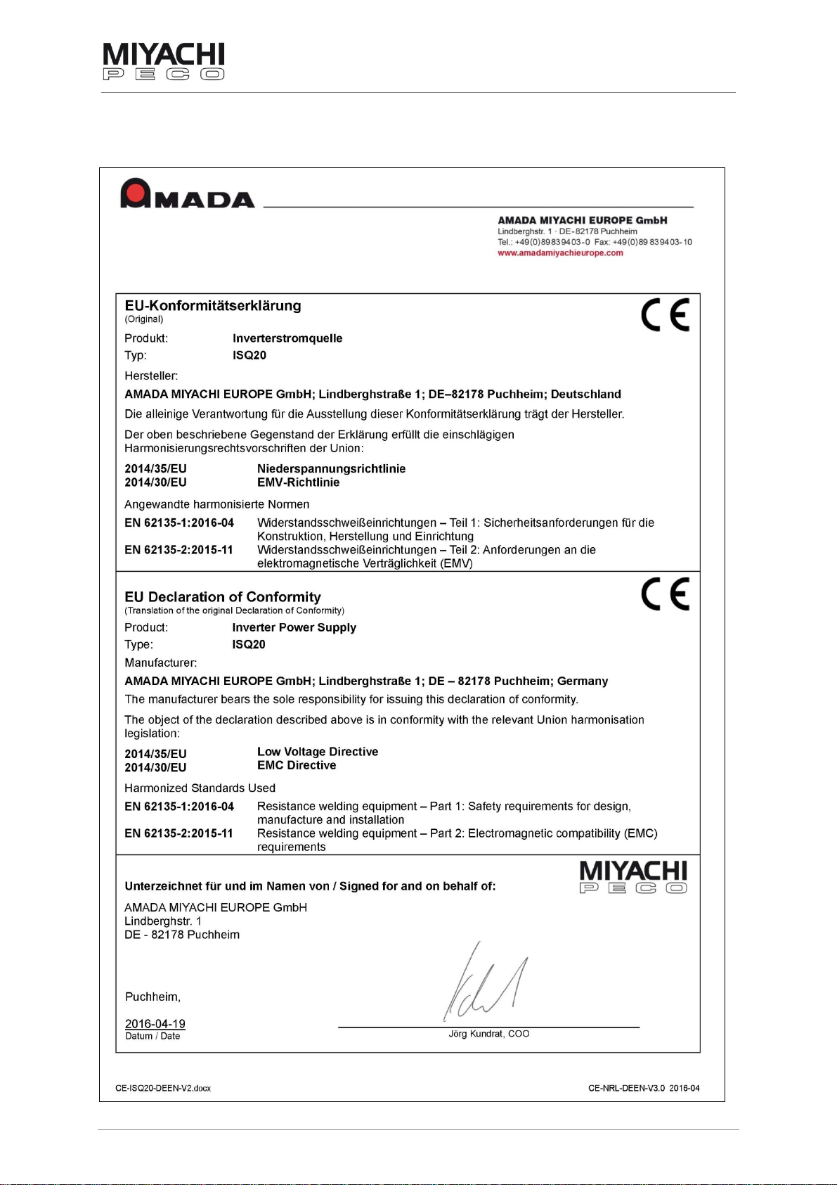
1.3Declaration of Conformity.................................................................................................7
2Technical Description..........................................................................................8
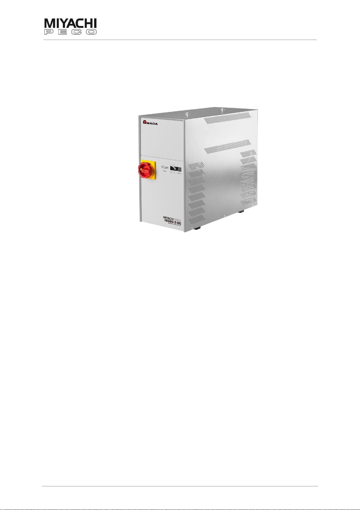
2.1Device Types ......................................................................................................................9
2.1.1Technical Data ISQ20-3-DC.............................................................................................................10
2.1.2Technical Data ISQ20-6-DC............................................................................................................. 11
2.1.3Technical Data ISQ20-10-DC...........................................................................................................12
2.1.4Technical Data ISQ20-20-DC...........................................................................................................13
2.1.5Technical Data ISQ20-8-AC .............................................................................................................14
2.2Operation..........................................................................................................................15
2.3Displacement Sensor (optional, only usable with OP-AWS3/TP-AWS3)....................15
2.4Pressure/Force Measuring (optional, only usable with OP-AWS3/TP-AWS3)...........15
2.5Sound Pressure Level.....................................................................................................15
2.6Maximum Duty Ratio .......................................................................................................16
3Design and Mode of Action...............................................................................17
3.1Front Panel ISQ20............................................................................................................17
3.2Rear Panel ISQ20-3 / ISQ20-6..........................................................................................18
3.3Rear Panel ISQ20-8 / ISQ20-10........................................................................................19
3.4Rear Panel ISQ20-20........................................................................................................20
4Connections.......................................................................................................21
4.1Overview...........................................................................................................................21
4.2RS232 Serial Interface .....................................................................................................21
4.2.1Data Transfer ...................................................................................................................................21
4.2.2Data Output Format, AWS3 Mode....................................................................................................22
4.2.3Data Output Format, Classic Mode..................................................................................................23
4.2.4Baud Rate ........................................................................................................................................23
4.2.5Software Update ..............................................................................................................................23
4.3Plug Assignments............................................................................................................24
4.3.1X1: Binary Inputs, potential free .......................................................................................................24
4.3.2X2: Binary Outputs, potential free ....................................................................................................27
4.3.3X3: Initiators .....................................................................................................................................30
4.3.4X4: Valves ........................................................................................................................................32
4.3.5X5: Start ...........................................................................................................................................32
4.3.6X6: Proportional Valve Head 1 .........................................................................................................33
4.3.7X7: Pressure Sensor Head 1 ...........................................................................................................33
4.3.8X8: Proportional Valve Head 2 .........................................................................................................33
4.3.9X9: Pressure Sensor Head 2 ...........................................................................................................34
4.3.10X10: Voltage Measurement 1...........................................................................................................34
4.3.11X11: Voltage Measurement 2 ...........................................................................................................34
4.3.12X12: Binary I/O.................................................................................................................................34
4.3.13X30: Welding Transformer ...............................................................................................................35
4.3.14X31: Temperature Sensor Transformer ............................................................................................35
4.3.15X32: Current Measuring Coil............................................................................................................35

ISQ20
Content
76609605EN-ISQ20-V1.2.docx 4/63
5Commissioning..................................................................................................36
5.1Preconditions for Commissioning.................................................................................36
5.2Electrical Connections....................................................................................................36
5.2.1Mains Supply ...................................................................................................................................37
5.2.2Connecting Secondary Cables.........................................................................................................38
5.2.3Connecting Current Measurement ...................................................................................................39
5.3Mechanical Connections.................................................................................................40
5.3.1Connection Possibilities Heads / Valves etc.....................................................................................40
5.3.2Connection with One Head and Start 1............................................................................................41
5.3.3Connection with Two Heads and Start 1, 2 or 3 ...............................................................................42
5.4Insulation Test..................................................................................................................43
5.5Switching-on.....................................................................................................................43
6Sequence............................................................................................................44
6.1Standard Diagram with One Head..................................................................................44
6.2Diagram for One Head with Stroke Cylinder.................................................................45
6.3Diagram for Pincers resp. Locking Cylinder.................................................................46
7Error Messages..................................................................................................47
7.1Unit Errors (#10 – #59).....................................................................................................47
7.2Sequence Errors (#60 – #95)...........................................................................................49
8Connection Variants (Examples)......................................................................50
8.1ISQ20 - pneumatic 1-Head w/o Distance Measurement...............................................50
8.2ISQ20 - pneumatic 1-Head w/o Distance Measurement...............................................51
8.3AWS3 - pneumatic 1-Head...............................................................................................52
8.4AWS3 - pneumatic 2-Head...............................................................................................53
8.5AWS3 – pneumatic with Profibus...................................................................................54
8.6AWS3 – pneumatic with Ethernet IP ..............................................................................55
8.7AWS3 - motorized 1-Head ...............................................................................................56
8.8AWS3 - motorized 2-Head ...............................................................................................57
8.9AWS3 - motorized 1-Head with Profibus .......................................................................58
8.10AWS3 - motorized 1-Head with Ethernet IP...................................................................59
8.11AWS3 – motorized 1-Head with Router (Remote Service)...........................................60
9Connection Schemes ........................................................................................61
9.1Binary Connections 1......................................................................................................61
9.2Binary Connections 2......................................................................................................62
10Index ...................................................................................................................63
10.1Illustration Index ..............................................................................................................63
10.2Headword Index ...............................................................................................................63

ISQ20
General Information
76609605EN-ISQ20-V1.2.docx 5/63
1 General Information
1.1 Safety Notes
Information about safety regulations, symbols, copyrights, protection rights,
usage location conditions and notes on resistance welding can be found in the
back section of these operating instructions.
Please read this information carefully before using these operating instructions.
These operating instructions should help you familiarize yourself with the system and
take advantage of its application possibilities when used as directed.
It contains important notes to help operate the unit safely, properly, and economically.
Observing the notes will help avoid risks, decrease repair costs and down times, and
enhance reliability and the service life of the unit.
It is a rule: Safety first!
Warning
Incorrect or inappropriate configuration, installation, settings, handling or use can cause
mechanical, electrical or thermal hazards, which may result in serious damage or injury.
Ensure the correct execution of these points and follow the respective notes in the
operating instructions.
Danger
Do not put the system into operation before you have read the operating instructions!
Danger Persons with cardiac pacemakers and metallic implants are prohibited from
approaching to within a radius of at least 5 m of welding equipment!
Crushing Hazard
There is a risk of crushing during the adjustment movement due to closing electrodes,
stops for limiting adjustment or stroke movement and the stop on the basic pincers unit
for limiting floating movement.
Warning
This Class A welding equipment is not supposed to be used in living quarters, where
the power supply is carried out by a public low voltage supply.
There it can be difficult to ensure electromagnetic compatibility because of conducted or
radiated disturbances.
Warning

ISQ20
General Information
76609605EN-ISQ20-V1.2.docx 6/63
1.2 Installation Notes
Please observe the following additionally to the points in chap. 5.1:
Ventilation:
To ensure adequate ventilation of the weld control and motor control units, the distance
on the side must be at least 40 mm and behind at least 100 mm.
19“ units (installation in a control cabinet):
ISQ20 - 1 U distance upwards
MNC (motor control) – at least 40 mm distance on the lateral ventilation slots
If the distances are too small, it can lead to increased temperatures in the inside of the
unit. This can affect the functionality.
Cable routing:
For the cable routing ensure an appropriate separation of control and field bus cables to
power cables, motor cables and cables with welding current.
EMC guidelines – and thus also the distances to arising magnetic fields – have to be
observed.
An appropriate shielding has to be scheduled if necessary.

ISQ20
General Information
76609605EN-ISQ20-V1.2.docx 7/63
1.3 Declaration of Conformity

ISQ20
Technical Description
76609605EN-ISQ20-V1.2.docx 8/63
2 Technical Description
The inverter power supply ISQ20 (hereinafter also referred to as inverter or weld
control) can be used as a stand-alone unit with the operating terminal MFT1 or as part of
the AWS3 (Active Welding System 3) with the operating terminals OP-AWS3 or
TP-AWS3.
Fig. 1: Standard device
A few important functions:
APC (Active Part Conditioner)
Setting of pre-warning and limit values
Error control and process monitoring
Displacement / Force measuring (optional, only possible with AWS3 operating
terminal and appropriate measurement technology))
The control mode for each welding pulse can be pre-selected in each of the 99 programs
of the ISQ20.

ISQ20
Technical Description
76609605EN-ISQ20-V1.2.docx 9/63
2.1 Device Types
The ISQ20 is available in the following DC- and AC types:
DC device with internal transformer:
ISQ20-3-DC
ISQ20-6-DC 3 kA
6 kA
DC device with external transformer:
ISQ20-10-DC 10 kA consisting of basic device
ISQ20-EXT-AC/DC-250
and transformer IT-60X *
DC device with external transformer and external line filter:
ISQ20-20-DC 20 kA consisting of basic device
ISQ20-EXT-AC/DC-500,
transformer IT-113X * and external line filter
AC device with external transformer:
ISQ20-8-AC 8 kA consisting of basic device
ISQ20-EXT-AC/DC-250
and transformer TRM3/14 – 9V *
* Other transformers on request.
Special voltages for different mains supplies on request.

ISQ20
Technical Description
76609605EN-ISQ20-V1.2.docx 10/63
2.1.1 Technical Data ISQ20-3-DC
Supply voltage 3x 400 VAC, ±10%, PE
Mains frequency 50...60 Hz
Connecting cable 4 x 2.5 mm²
Connected load 11 kVA
Fuse recommended 3 x 16 A, slow
Rated output current 2 kA at 11 % d.r. measured for Tu = 20 °C
Max. output current 3 kA at 5 % d.r.
Min. terminal voltage 4 V at 3 kA with 400 V rated mains voltage at
the unit input
Max. open circuit voltage 10 V
Max. output power 12 kVA
Switching frequency 20 kHz
Output frequency 40 kHz
Protection class IP 30
Permissible humidity 40 – 70 %, non-condensing
Ambient temperature 10..40 °C
Cooling forced ventilation, temperature controlled
Secondary connections Cu busbar, 2 x M8 thread
Minus connected with PE
Current measurement integrated measuring coil (toroidal coil)
Dimensions
(W x H x D) 216 x 420 x 480 mm
216 x 420 x 550 mm (incl. excess lengths)
Weight ca. 33 kg

ISQ20
Technical Description
76609605EN-ISQ20-V1.2.docx 11/63
2.1.2 Technical Data ISQ20-6-DC
Supply voltage 3x 400 VAC, ±10%, PE
Mains frequency 50...60 Hz
Connecting cable 4 x 2.5 mm²
Connected load 11 kVA
Fuse recommended 3 x 16 A, slow
Rated output current 3 kA at 20 % d.r. measured for Tu = 20 °C
Max. output current 6 kA at 5 % d.r.
Min. terminal voltage 4 V at 6 kA with 400 V rated mains voltage at
the unit input
Max. open circuit voltage 10 V
Max. output power 24 kVA
Switching frequency 14 kHz
Output frequency 28 kHz
Protection class IP 30
Permissible humidity 40 – 70 %, non-condensing
Ambient temperature 10..40 °C
Cooling forced ventilation, temperature controlled
Secondary connections Cu busbar, 2 x M8 thread
Minus connected with PE
Current measurement integrated measuring coil (toroidal coil)
Dimensions
(W x H x D) 216 x 420 x 480 mm
216 x 420 x 550 mm (incl. excess lengths)
Weight ca. 43 kg

ISQ20
Technical Description
76609605EN-ISQ20-V1.2.docx 12/63
2.1.3 Technical Data ISQ20-10-DC
with IT-60X transformer:
Supply voltage 3 x 400 VAC, ±10 %, PE
Mains frequency 50...60 Hz
Connecting cable 4 x 6 mm²
Connected load 22 kVA
Fuse recommended 3 x 32 A, slow
Rated output current dep. on transformer measured for Tu = 20 °C
Max. output current 10 kA at 8 % d.r.
Min. terminal voltage 4 V at 10 kA with 400 V rated mains voltage at
the unit input
Max. open circuit voltage 10 V
Max. output power 40 kVA
Switching frequency 1-5 kHz (dependent on primary current)
Output frequency 2-10 kHz
Protection class IP 30
Permissible humidity 40 – 70 %, non-condensing
Ambient temperature 10..40 °C
Cooling forced ventilation, temperature controlled;
transformer water cooled
Secondary connections dep. on transformer
Current measurement external measuring coil
Dimensions inverter
(W x H x D) 216 x 420 x 480 mm
216 x 420 x 560 mm (incl. excess lengths)
Dimensions transformer
(W x H x D) 284 x 110 x 170
Weight inverter ca. 21 kg, transformer ca. 60 kg

ISQ20
Technical Description
76609605EN-ISQ20-V1.2.docx 13/63
2.1.4 Technical Data ISQ20-20-DC
with IT-113X transformer:
Supply voltage 3 x 400 VAC, ±10 %, PE
Mains frequency 50...60 Hz
Connecting cable 4 x 35 mm²
Connected load 85 kVA
Fuse recommended 3 x 100 A, slow
Rated output current dep. on transformer measured for Tu = 20 °C
Max. output current 20 kA at 15 % d.r.
Min. terminal voltage 3 V at 25 kA with 400 V rated mains voltage at
the unit input
Max. open circuit voltage 11 V
Max. output power 75 kVA
Switching frequency 1-5 kHz
Output frequency 2-10 kHz
Protection class IP 30
Permissible humidity 40 – 70 %, non-condensing
Ambient temperature 10..40 °C
Cooling inverter and transformer: water cooled
Secondary connections dep. on transformer
Current measurement external measuring coil
Dimensions inverter
(W x H x D) 216 x 420 x 480 mm
216 x 420 x 570 mm (incl. excess lengths)
Dimensions transformer
(W x H x D) 420 x 125 x 230 mm
Dimensions line filter
(W x H x D) 250 x 230 x 600 mm
250 x 230 x 680 mm (incl. excess lengths)
Weight inverter ca. 32 kg, transformer ca. 25.5 kg
line filter ca. 19 kg

ISQ20
Technical Description
76609605EN-ISQ20-V1.2.docx 14/63
2.1.5 Technical Data ISQ20-8-AC
with TRM3/14
transformer:
Supply voltage 3 x 400 VAC, ±10 %, PE
Mains frequency 50...60 Hz
Connecting cable 4 x 6 mm²
Connected load dependent on main stage
Fuse recommended dependent on main stage
Rated output current dep. on transformer
Max. output current dep. on transformer
Min. terminal voltage dep. on transformer with 400 V rated mains voltage at
the unit input
Max. open circuit voltage dep. on transformer
Max. output power 25 kVA
Switching frequency 1-10 kHz
Output frequency 1-10 kHz
Protection class IP 30
Permissible humidity 40 – 70 %, non-condensing
Ambient temperature 10..40 °C
Cooling forced ventilated, temperature controlled;
transformer water cooled
Secondary connections dep. on transformer
Current measurement external measuring coil
Dimensions inverter
(W x H x D) 216 x 420 x 480 mm
216 x 420 x 560 mm (incl. excess lengths)
Dimensions transformer
(W x H x D) 360 x 150 x 185 mm
Weight inverter ca. 21 kg, transformer ca. 45 kg

ISQ20
Technical Description
76609605EN-ISQ20-V1.2.docx 15/63
2.2 Operation
The operation of the ISQ20 is made with one of the following operating terminals:
OP-AWS3:
TP-AWS3:
MFT1:
AWS3 operating terminal with toggle wheel
AWS3 operating terminal with touch panel
Operating terminal with buttons
Find more information regarding the operating terminals in the respective operating
instruction.
2.3 Displacement Sensor (optional, only usable with OP-AWS3/TP-AWS3)
Dependent on used weld head.
Article no. Name
770.66 186 Displacement sensor ST1278
770.66 318 Displacement sensor ST3078
770.66 263 Displacement sensor MT1271
770.66 317 Displacement sensor MT2571
Digital (5V/TTL)
Resolution: 0.1 μm / 1 μm / 2 μm
Digital double sampling
2.4 Pressure/Force Measuring (optional, only usable with OP-AWS3/TP-AWS3)
Dependent on used weld head.
0 – 10 V calibration
Voltage detection set values: potential free, connection external X7 / X9
Information regarding necessary measuring parts on request.
2.5 Sound Pressure Level
The equivalent continuous sound pressure level evaluated as Ais below 70 dB.

ISQ20
Technical Description
76609605EN-ISQ20-V1.2.docx 16/63
2.6 Maximum Duty Ratio
Duty ratio (d.r.) relative to the set welding current:
Fig. 2: Maximum duty ratio
For ISQ20 with external transformer (ISQ20-8, ISQ20-10 and ISQ20-20) the duty ratio is
dependent on the used transformer.
See transformer data sheet for the respective characteristic line.
0
10
20
30
40
50
60
00,511,522,533,5
ED in%
I in kA
ISQ20-3
ED…
0
10
20
30
40
50
60
02468
ED in %
I in kA
ISQ20-6
ED…

ISQ20
Design and Mode of Action
76609605EN-ISQ20-V1.2.docx 17/63
3 Design and Mode of Action
3.1 Front Panel ISQ20
Main switch
Status display and
error messages
RS232
Fig. 3 Front panel
On the front panel you find:
the main switch
the RS232 interface
the display for status and error messages
Status display:
1 2 3
STATUS
4 5 6
Abb. 4 Display
7
1 LED
green
Ready 4 LED red Quick-Stop
2 LED
green
Pressure contact
(DK) 5 LED red Out of Limits
3 LED
green
Stepping contact
(FK)
6 LED red Sequence error
7 Status messages
00 Ready Operating voltage is present, system is OK,
intermediate circuit is not charged
01 Converter ON Intermediate circuit successfully charged.
Unit is ready for operation.
02 Controller free
03 Welding program
running
04 Reference run active

ISQ20
Design and Mode of Action
76609605EN-ISQ20-V1.2.docx 18/63
3.2 Rear Panel ISQ20-3 / ISQ20-6
X13
S3
X14
X1 X2
X3 X4 X12
S1 S2
X6 X7 X8 X9
X10
X11
X5
XN
Abb. 5: Rear panel ISQ20-3 / ISQ20-6
+
-

ISQ20
Design and Mode of Action
76609605EN-ISQ20-V1.2.docx 19/63
3.3 Rear Panel ISQ20-8 / ISQ20-10
X13
S3
X14
X1 X2
X3 X4 X12
S1 S2
X6 X7 X8 X9
X10
X11
X5
X32
X31
34 56
1 2 PE
X30
XN
Abb. 6: Rear panel ISQ20-8 / ISQ20-10

ISQ20
Design and Mode of Action
76609605EN-ISQ20-V1.2.docx 20/63
3.4 Rear Panel ISQ20-20
X13
S3
X14
X1 X2
X3 X4 X12
S1 S2
X6 X7 X8 X9
X31
X32
X10
X11
X5
U L1
V L2
X30 L3
PE
IN OUT
Abb. 7: Rear panel ISQ20-20
XN
This manual suits for next models
5
Table of contents