manuals.online logo
Brands
  1. Home
  2. •
  3. Brands
  4. •
  5. MobileView
  6. •
  7. Switch
  8. •
  9. MobileView 3200 User manual

MobileView 3200 User manual

P/N 1073097A • REV 01.01 • NOV 2015 1
Introduction
The MobileView Network Switch (MVNS) 3200 is a cost-effective,
unmanaged network switch optimized for use with IP based video
recording systems. The switch is available in 8 or 16 port models
each having two Gigabit uplink ports and 48VDC PoE fast
Ethernet downlink ports. The construction is rugged and features
a simplified status interface, integrated cable management,
passive cooling, and maximized functions necessary for remote
installation in challenging vehicular environments.
Features
• 8 and 16 port models
• Support for 16 IP cameras at 1080p resolution, 30fps
• 7.2 Gbps switching capacity
• Available upgrades:
- Hardware: expands 8 ports to 16 ports
- Firmware: updates using web interface
• Simplified LED status indicators
• Fault relay for remote monitoring
• Available 51/102 Watts for PoE (8/16 Channel)
• Cable management bars and clips included
• Integrated mounting flange
• Standardized connection harness
• SAE-J1455 Compliance Tested
MVNS-3200 Functionality
The MVNS-3200 provides connectivity for up to 8 or 16 IP
cameras with compatible MobileView network video recorders.
Ports
The MVNS-3200 has uplink and downlink ports providing
connectivity between the recorder and other network devices.
1. Uplink Port: Dual 1GB Ethernet ports are provided. While
both ports are general purpose, the one labeled NVR is
intended for connection to the network video recorder and the
other for connection to a second switch or other network
device.
2. Downlink Port: Depending on model, up to 8 or 16 Fast
Ethernet downlink ports are available. While available for
connection to any network device, these ports are optimized
for connection to MobileView IP cameras. Ports include PoE
capability.
Power over Ethernet (PoE)
Downlink ports include PoE for connection to powered IP devices.
Available power is optimized for MobileView IP cameras. Each set
of 8 downlink ports has a maximum of 51 watts available to split
across all ports (target = 6.375W) with each individually limited to
25.5 watts. If either limit is exceeded, the switch will trigger a fault
and ports may not function properly. The switch automatically
reverts to normal operation once power levels come within the
specified limits.
Camera IP Auto-Assignment
The MVNS-3200 is optimized for connection to MobileView IP
cameras with an expected uplink connection to MobileView
network video recorders. By default, the switch detects
compatible IP cameras and automatically assigns each a unique
IP addresses according to the downlink port ID. Address
assignment follows this scheme:
Port 1 = 192.168.1.101
Port 2 = 192.168.1.102
Port 3 = 192.168.1.103
Port XX = 192.168.1.1XX
The auto assignment function is enabled by default. It can be
disabled in the switch configuration.
Configuration
The MVNS-3200 implements limited configuration using a built-in
web server at the fixed IP address 192.168.1.64. Available
options include firmware update, camera IP auto-assignment, and
logout user. Future firmware may enable new or expanded
features and controls.
Caution: Configuration changes are effective immediately.
Firmware Update
To update the MVNS-3200 firmware:
1. Open the configuration page.
2. Press Browse.
3. Select the firmware filename.
4. Press OK to load the text box with the firmware filename and
location.
MobileView®Network Switch Quick Reference
2 MobileView Network Switch Quick Reference
5. Press Upgrade to start the process and follow the on screen
prompts to complete. The switch will reboot upon completion
of the upgrade process.
Reboot & Factory Default
The MVNS-3200 includes a special purpose button used to
manually reset the switch if it becomes unresponsive. To reset,
insert a blunt tipped, non-metal object like a toothpick into the hole
above the word reboot on the front of the switch until the
recessed button is activated. After 1 second, remove the object
and the switch will reboot.
To restore the device to factory defaults, hold the button pressed
for 10 seconds. Upon object removal the switch will reboot and be
configured to factory default settings.
Status Indicators
The MVNS-3200 displays the system status with two LED and
one relay output.
The fault relay is active under normal conditions. This ensures
that remote systems monitoring the switch observe a fault
condition when the switch is OFF.
During the start up process the relay may change several times.
Once the relay is in operational state, it will become stable.
Installation
The MVNS-3200 incorporates an integral mounting flange with
four (4) precut bolt holes. To mount the switch:
1. Use the switch base as a template to mark and drill four (4)
holes in the mounting surface.
2. Using bolts, locking washers, and nuts, mount the switch to
the vehicle surface.
Note: If necessary, precut bolt holes may be widened to
support up to ¼” diameter bolts.
Mounting
The MVNS-3200 is optimally designed for horizontal mounting to
a flat and vibration resistant surface. Since it is a solid state device
with no moving parts, the switch may be mounted in any
orientation without effect on operational capabilities.
Caution: The switch utilizes passive cooling through a network
of fins along the bottom of the device. These fins rely on air
movement to function. Do not mount the switch to surfaces that
restrict air movement such as carpet.
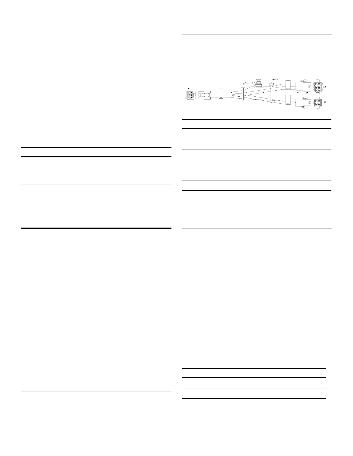
Harness & Connections
The MVNS-3200 has a single harness with two connectors to
attach field wires. The connector and pin schedule are as shown.
Caution: When making connections to the switch or harness,
ensure the vehicle power is off or disconnected.
Caution: Power connections from the vehicle to the harness
must use 16AWG capable of carrying up to a 7.5 amp load.
Caution: Use 7.5A ATO replace fuse only.
The switch is designed to have main power and ground applied all
the time without starting. The device will initiate startup only when
the power control input is present and will shut down when the
control signal is absent.
Note: Connect the switch power control input to a 12V output
from the recorder that is ON when the recorder is
running. This will ensure the switch is ON when the
recorder is ON.
Note: Refer to Electrical Specifications for acceptable power
control input voltage values.
Input Voltage
The MVNS-3200 works within the following voltage ranges.
Feature Type Use/Comment
Main Power LED Indicates power state
Red = Power Available
Red Blink = Booting
Green = Device ON
Fault LED Indicates fault state
Off = Normal
Amber = Fault
Fault Relay Indicates fault state
Active = Normal
Inactive = Fault
Switch Color Use Field
X1.1 Red Main PWR (+) Fused 7.5A X2.1 & X2.4
X1.2 Black GND X2.2 & X2.5
X1.3 White PWR Control (+) X2.3 & X2.6
X1.4 Brown Fault Relay (NC) X3.1
X1.5 Blue Fault Relay (C) X3.2
X1.6 White Fault Relay (NO) X3.3
Model Input Voltage Supported Range Power Out
8-Port 12V/24V Low = 9VDC, High = 32VDC 51W
16-Port 24V Only Low = 16VDC, High = 32VDC 102W
MobileView Network Switch Quick Reference 3
Note: Always use the correct input voltage range to avoid
exceeding power out limits. Installing a 16 port model
onto a 12 volt system will blow the fuse when output
power causes the device to draw more than 7.5 amps of
input power.
Note: The 8-port switch requires a minimum 10.8VDC to start.
Once running, the device operate down to 9VDC.
Cable Management Bar
The MVNS-3200 includes cable management bars for cable
routing, strain relief, and clean installation. The longer bar
attaches to the front of the switch assembly and is used with an 8
port model. The second bar is shorter and attaches over ports 9-
16 of the 16 port model. Use of the management bars is optional.
8-Port Expander Module
The MVNS-3200 8 port switch can be expanded to 16 ports by
installing an 8 port expander module. Follow these steps to install
the expander.
1. Remove the power from the switch.
2. Remove the cover plate on right side of the switch.
3. Locate the slide rails in the expansion slot.
4. Align the expander module base plate with slide rails.
5. Slide the entire expander into switch body.
6. Screw the expander in place.
7. Ensure the expander trim ring is flush with switch front.
8. Inspect the expander before applying power.
Once installed, the switch automatically recognizes the expander
and starts working without any special programming or
configuration. If the switch fault light illuminates, remove power
and try resetting the expander.
Specifications
Physical
Switching
Electrical
Technical Support
http://www.interlogix.com/mobileview
Email: [email protected]
Phone: 1-855-MOB-VIEW (662-8439)
© 2015 United Technologies Corporation. All rights reserved.
All trademarks are the property of their respective owners.
Interlogix is part of UTC Climate, Controls & Security, a unit of
United Technologies Corporation.
Indicators Power (Bi color LED, Red/Green)
Fault (LED, Amber)
Connectors 6-Pin Molex Plug Housing
Harness 15" Quick Connect Type
Ethernet Standards IEEE802.3i (10BASE-T)
IEEE802.3u (100BASE-TX)
IEEE802.3ab (1000BASE-T)
Uplink Ports 2x Gigabit Ethernet
Downlink Ports 8x Fast Ethernet (8 Port Model)
16x Fast Ethernet (16 Port Model)
Switch Technology Store and Forward
Protocol CSMA/CD
MAC Table Size 8KB
RAM Buffer 1MB
Switching Capacity 7.2 Gbps
IP Camera Capacity 16 IP Cameras @ 1080p, 30fps
Input Voltage 9 to 32 VDC (8 Port Model)
16 to 32 VDC (16 Port Model)
Input Current 7.5 Amp
Power Control 0-1VDC = OFF
5-32VDC = ON
Output Power 51 Watts Max (8 Port Model)
102 Watts Max (16 Port Model)
PoE Output 802.3at
48VDC @ 25.5A max per port
Output Relay DPST, Form C, Dry Contact
4 MobileView Network Switch Quick Reference

Popular Switch manuals by other brands

Extron electronics SW4 ARxi user guide

Extron electronics

Extron electronics SW4 ARxi user guide

LevelOne SoHoCon FSW1602TX Specifications

LevelOne

LevelOne SoHoCon FSW1602TX Specifications

Matsushima PFM-DWS10 instruction manual

Matsushima

Matsushima PFM-DWS10 instruction manual

Techly IDATA HDMI-4K31 user manual

Techly

Techly IDATA HDMI-4K31 user manual

Micro Innovations 7-Port USB Hub USB710P Quick installation guide

Micro Innovations

Micro Innovations 7-Port USB Hub USB710P Quick installation guide

Balluff NAMUR BES G06MD-GNX10B-EV02-EEX operating instructions

Balluff

Balluff NAMUR BES G06MD-GNX10B-EV02-EEX operating instructions

Ruijie RG-NBS5200 Series Hardware  installation and reference guide

Ruijie

Ruijie RG-NBS5200 Series Hardware installation and reference guide

3Com 3CRUS2475 24 Command reference guide

3Com

3Com 3CRUS2475 24 Command reference guide

EMC Connectrix DS-24M2 user guide

EMC

EMC Connectrix DS-24M2 user guide

AMF Switches and Diverters brochure

AMF

AMF Switches and Diverters brochure

Sunricher SR-SBP2801K4-FOS instruction manual

Sunricher

Sunricher SR-SBP2801K4-FOS instruction manual

Vimar NEVE UP 09592.2 manual

Vimar

Vimar NEVE UP 09592.2 manual

3Com SuperStack 3 3C16477 user guide

3Com

3Com SuperStack 3 3C16477 user guide

Siemens RUGGEDCOM RSG2488 installation guide

Siemens

Siemens RUGGEDCOM RSG2488 installation guide

Philips CBTD3306 Product data sheet

Philips

Philips CBTD3306 Product data sheet

EverFocus ES1625-31 user manual

EverFocus

EverFocus ES1625-31 user manual

ENFORCER MVM-AH44-01YQ user manual

ENFORCER

ENFORCER MVM-AH44-01YQ user manual

Blue Sea Systems 8280 Handbook

Blue Sea Systems

Blue Sea Systems 8280 Handbook

manuals.online logo
manuals.online logoBrands
  • About & Mission
  • Contact us
  • Privacy Policy
  • Terms and Conditions

Copyright 2025 Manuals.Online. All Rights Reserved.