Modular AN003 MPT11210IL User manual

Page 1 www.modularpowertech.com AN003_MPT11210IL-EVB_Rev2.1
APPLICATION NOTE
AN003_MPT11210IL Evaluation Board User Guide
Introduction
The MPT11210IL are fully integrated step down DCDC converters with control, gate drive, compensation,
MOSFET switches, and high performance magnetics. They come in an advanced 11mm x 11mm x 4.59mm 76-
pin open frame package, and require only a small number of external components to make complete converter
solutions. This user guide should be used together with the latest MPT11210IL datasheets for detailed Output
Voltage, Switching Frequency, and Compensation settings.
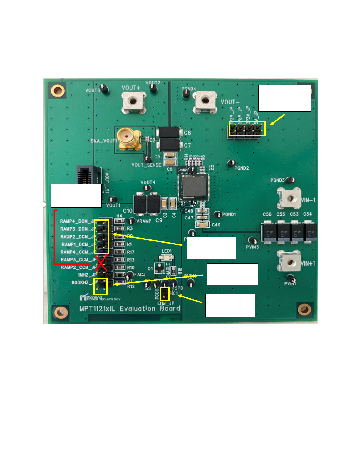
The following are the features of this evaluation board.
• Populated with one MPT11210IL.
• Pads are available for a wide range of input and output capacitor configurations.
• Output voltage programming is accomplished via a simple resistor divider. Jumpers are
provided for 5 pre-configured output settings. These settings are as follows:
0.6V, 1.2V, 1.8V, 3.3V, 5.0V. For output voltage settings other than the pre-configured options, please
refer to the “Setting Output Voltages” section in this user guide.
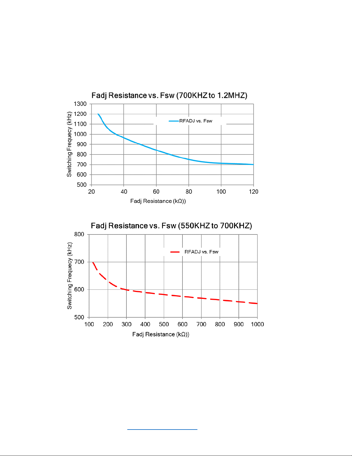
• Switching Frequency programming is accomplished via a simple pulldown resistor. Jumpers are
provided for 3 pre-configured frequency settings. These settings are as follows:
550kHZ, 750kHZ, 900kHZ, where 550kHZ is the default setting with no jumper installed. For switching
frequency settings other than the pre-configured options, please refer to the “Setting Switching
Frequencies” section in this user guide.
• An internal ramp generator can be adjusted for system stability via a simple pulldown resistor. Jumpers
are provided for 5 pre-configured compensation settings. Please refer to the “Setting VRAMP” section
in this user guide.
• Easy jumper setting for Enable and Disable Functions.
• Numerous test points are provided as well as clip leads for input and output connections.
• The board comes with input decoupling.

Page 2 www.modularpowertech.com AN003_MPT11210IL-EVB_Rev2.1
Figure 1 shows a photograph of the evaluation board. Please refer to this while
configuring the board for evaluation.
Figure 1: MPT11210IL Evaluation Board
Output Voltage
select jumpers
Enable/Disable
select jumper
Frequency
select jumpers
Compensation
select jumpers
Don’t use
CCM jumpers

Page 3 www.modularpowertech.com AN003_MPT11210IL-EVB_Rev2.1
SETTING OUTPUT VOLTAGES
There are 5 pre-configured output voltage options to choose from by placing the
appropriate jumper. Those output voltages are: 0.6V, 1.2V, 1.8V, 3.3V, and 5V where
0.6V option is the default Vout with no jumper installed. To choose output voltage settings
other than those pre-configured on this evaluation board, REMOVE R9, R8, and R7, and
REPLACE R6 per the formulas below and set the jumper 5V_JP accordingly.
!
!
R6 =
!"#$%$&'()
&*+,-&'()
Since R14 = 20kΩ"and VREF = 0.6V, the equation becomes:
R6 =
".
&*+,-/01

Page 4 www.modularpowertech.com AN003_MPT11210IL-EVB_Rev2.1
SETTING SWITCHING FREQUENCY
There are 3 pre-configured switching frequency options to choose from by placing the
appropriate jumper. Those switching frequencies are: 550kHZ, 750KHZ, and 900kHZ
where 550KHZ is the default switching frequency with no jumper installed. The figure
below shows the recommended switching frequency for various output voltage settings.
Figure 2: Recommendation chart for Fsw and associated Output Voltage setting

Page 5 www.modularpowertech.com AN003_MPT11210IL-EVB_Rev2.1
To choose switching frequency settings other than those pre-configured on this evaluation
board, REMOVE R12, and REPLACE R11 per the table below and set the jumper
1MHZ_JP accordingly.
!
Figure 3: FADJ Resistance (R11) setting and associated switching frequencies

Page 6 www.modularpowertech.com AN003_MPT11210IL-EVB_Rev2.1
SETTING VRAMP/COMPENSATION
The internal ramp generator can be adjusted for system stability. There are 5 pre-
configured compensation settings to choose from by placing the appropriate jumper.
Typically, the default setting with NO jumper installed results in stable operation of the
converter. Please see table below for compensation settings:
!
Figure 4: VRAMP jumper settings to set internal ramp generator voltage level
Vramp Voltage (VRAMP)
Vramp
Amplitude
VRAMP Jumper
VRAMP < 1/16*VDD Vramp1 RAMP1_DCM_JP
1/16*VDD < VRAMP < 3/16*VDD Vramp2 RAMP2_DCM_JP
3/16*VDD < VRAMP < 5/16*VDD Vramp3 RAMP3_DCM_JP
5/16*VDD < VRAMP < 7/16*VDD Vramp4 RAMP4_DCM_JP
VRAMP >15/16*VDD Vramp1 OPEN
Vramp level is: Vramp1 < Vramp2 < Vramp3 < Vramp4

Page 7 www.modularpowertech.com AN003_MPT11210IL-EVB_Rev2.1
BOARD POWER UP PROCEDURE
STEP 1: Initially disable the MPT11210IL by placing a jumper on the “ENB_JP” 2 pin
header.
STEP 2: Select the desired VOUT voltage setting by placing a jumper on the correct
output voltage select header pins.
Below shows the VOUT jumper options:
• VOUT = 5V, connect jumper on 5V_JP
• VOUT = 3.3V, connect jumper on 3P3V_JP
• VOUT = 1.8V, connect jumper on 1P8V_JP
• VOUT = 1.2V, connect jumper on 1P2V_JP
• VOUT = 0.6V, no jumper installed
STEP 3: Select the desired switching frequency setting by placing a jumper on the correct
frequency select header pins. Please refer to recommendation chart for Fsw vs Vout to
set the recommended switching frequency.
Below shows the switching frequency jumper options:
• Fsw = 900KHZ, connect jumper on 1MHZ_JP
• Fsw = 750KHZ, connect jumper on 800KHZ_JP
• Fsw = 550KHZ, no jumper installed

Page 8 www.modularpowertech.com AN003_MPT11210IL-EVB_Rev2.1
STEP 4: Select the desired compensation setting by placing a jumper on the correct
Vramp select header pins. Stable operation is typical when there is no jumper installed.
Please refer to the Vramp jumper setting chart to adjust the Vramp voltage levels.
CAUTION: the VOUT, Fsw, and VRAMP jumper settings should only be changed when
the device is disabled. Failure to follow this guideline may result in damage to the part.
STEP 5: Connect the Power Supply to the input power connectors, VIN (+) and VIN (-).
DO NOT turn the power supply on yet.
CAUTION: Be mindful of the polarity. Reversing polarity will result in damage to the part.
STEP 6: Connect an electronic load, or load board to the output connectors VOUT (+)
and VOUT (-).
STEP 7: Power up the board by removing the ENABLE jumper from the ENB_JP jumper
header pins. The MPT11210IL is now powered up and should have a regulated
output voltage at this point.!

Page 9 www.modularpowertech.com AN003_MPT11210IL-EVB_Rev2.1
TEST MEASUREMENT RECOMMENDATIONS
To guarantee measurement accuracy, the following precautions should be observed:
• Make all input and output voltage measurements at the board using the test points
provided. This will eliminate voltage drop across the line and load cables that can
produce false readings.
• Measure input and output current with series ammeters or accurate shunt
resistors. This is especially important when measuring efficiency.
• Use a balanced impedance probe tip across COUT to measure VOUT Ripple to avoid
noise coupling into the probe ground lead. The recommended probe configuration
is shown in Figure 2.
Figure 2. Recommended probe configuration.
Popular Motherboard manuals by other brands

Texas Instruments
Texas Instruments TPSI2140-Q1 user guide

Silego
Silego GreenPAK Universal Dev. Board 1 quick start guide

Intel
Intel DH61BF Integration guide

IEI Technology
IEI Technology tKINO-BW Series user manual

NXP Semiconductors
NXP Semiconductors i.MX RT1010 EVK quick start guide

Asus
Asus NCLV-D user manual