manuals.online logo
Brands
  1. Home
  2. •
  3. Brands
  4. •
  5. Moffat
  6. •
  7. Merchandiser
  8. •
  9. Moffat GO12 Instruction and safety manual

Moffat GO12 Instruction and safety manual

This manual suits for next models

7

Other Moffat Merchandiser manuals

Moffat M Series Instruction and safety manual

Moffat

Moffat M Series Instruction and safety manual

Moffat Happy Host HH1H Instruction and safety manual

Moffat

Moffat Happy Host HH1H Instruction and safety manual

Moffat Grab& Go D1GH Instruction and safety manual

Moffat

Moffat Grab& Go D1GH Instruction and safety manual

Popular Merchandiser manuals by other brands

FRIGOGLASS Flex 20 HC user manual

FRIGOGLASS

FRIGOGLASS Flex 20 HC user manual

Hussmann ENTYCE TY3 Installation & operation manual

Hussmann

Hussmann ENTYCE TY3 Installation & operation manual

EPTA COSTAN RHINO MULTI User instructions

EPTA

EPTA COSTAN RHINO MULTI User instructions

Hussmann CRFD Installation and operation guide

Hussmann

Hussmann CRFD Installation and operation guide

CASCO Nano Cube owner's manual

CASCO

CASCO Nano Cube owner's manual

Hussmann WDCHI Installation & operation manual

Hussmann

Hussmann WDCHI Installation & operation manual

True GDIM-26 installation manual

True

True GDIM-26 installation manual

Structural Concepts Oasis Mobile Series Installation & operating manual

Structural Concepts

Structural Concepts Oasis Mobile Series Installation & operating manual

Hussmann Q2-SS Installation & operation guide

Hussmann

Hussmann Q2-SS Installation & operation guide

Haussmann RL Installation & operation manual

Haussmann

Haussmann RL Installation & operation manual

Howard McCray R-CDS32E-4 Specifications

Howard McCray

Howard McCray R-CDS32E-4 Specifications

Hussmann microSC SHM-A Series Installation & operation manual

Hussmann

Hussmann microSC SHM-A Series Installation & operation manual

Hussmann APT0500 Installation & operation manual

Hussmann

Hussmann APT0500 Installation & operation manual

EPTA iarp Cool Emotions Delight Lite User instructions

EPTA

EPTA iarp Cool Emotions Delight Lite User instructions

VALERA BC 85 datasheet

VALERA

VALERA BC 85 datasheet

HL Display 3eBin Assembly instructions

HL Display

HL Display 3eBin Assembly instructions

Hussmann Q1-SS Technical data sheet

Hussmann

Hussmann Q1-SS Technical data sheet

Hussmann impact Excel C2X-XLEP Technical data sheet

Hussmann

Hussmann impact Excel C2X-XLEP Technical data sheet

manuals.online logo
manuals.online logoBrands
  • About & Mission
  • Contact us
  • Privacy Policy
  • Terms and Conditions

Copyright 2025 Manuals.Online. All Rights Reserved.

Manual 047 Issue 001 August 2023
Operating & Service Manual
Heated & Chilled Merchandisers
The appliance must only be used for the purpose it was designed for and may become unsafe
if used for any other purpose. Operators should be trained. The room where this trolley is
used must be dry, clean with temperatures between 16°C and 25°C and with a maximum
relative humidity of 60%. This unit is for indoor use only and has an IPX4 rating.
To ensure the best results from this unit please take the time to read and follow all safety,
installation and maintenance guidelines carefully before proceeding to install. Keep this manual
in a safe place for future consultation.
These appliances are marked in compliance with the relevant regulations Voltage stated on unit
data plate.
Warning! Please pay attention to sections of the manual displaying this symbol.
Warning! Do not attempt to use a hose or water jet to clean this unit.
or cleaning instructions, refer to section 15.
Warning! Depending on your unit model, this unit’s system may be charged
with a flammable refrigerant (R290).
Warning! The heated models display area exceeds 60°C.
Care must be taken when loading food.
Warning! Do not cover or block any internal or external air vents.
Warning! Always switch the unit o when not in use, before moving
and before cleaning or maintenance procedures.
Contents
Electrical Specification
General Specification
General Installation
Operation Heated model
Refrigerated Models Installation Conditions
Operation Refrigerated Models
Cleaning
1
2
3
4
5
6
7
Page
4
4
5 / 6
7 / 8 / 9
10 / 11
12
13
3
1: Electrical Specification
Live (L1)
L2
L3
Neutral
Earth
1 Phase Cable
Brown
X
X
Blue
Yellow & Green (Striped)
3 Phase Cable
Brown
Black
Grey
Blue
Yellow & Green (Striped)
This appliance must be earthed and damaged cables must be replaced by a suitably
qualified person!
A mains cable, type H07RN-F, conforming to code designation 60245 IEC 57, is supplied.
2: Specification
Model
GO12
GO13
GO14
GO22
GO23
GO24
GO13C
GO14C
Weight
(kg)
69
109
135
95
146
181
113
130
Electrical
Supply
13amp
13amp
13amp
13amp
32amp
32amp
13amp
13amp
Power Rating
(kw)
1.50
2.25
3.00
3.00
4.50
6.00
1.0
1.0
Dimensions
W X D X H (mm)
600 x 650 x 880
600 x 650 x 1580
600 x 650 x 1858
900 x 650 x 880
900 x 650 x 1580
900 x 650 x 1858
900 x 650 x 1580
900 x 650 x 1858
Chilled unit’s system are charged with flammable refrigerant (R290)
Before commencing there are certain environmental parameters that must be followed
please read the additional conditions on page 5 & 6
Each units must have a dedicated power supply. Refer to the data badge on the unit for
electrical ratings. The units are rated for a 230V 1PH 50Hz supply.
4
3: General Installation
Before installation please read the following points:
• When placing in position ensure there is adequate access.
• Ensure that the unit is installed on a flat even surface
• Ensue that the table or counter where table top type units are sited can safely support the weight of the unit.
• These units can simply be butted up together to form a food service line.
• Mobile types roll into position and apply the brakes.
• Before installing, it is recommended that the floor is swept clean.
This equipment is designed to be operated by suitably qualified persons. It is the
responsibility of the Supervisor or equivalent to instruct users, provide suitable P.P.E.,
show the mains isolating switch location, and inform users that parts may become hot,
causing injury if touched.
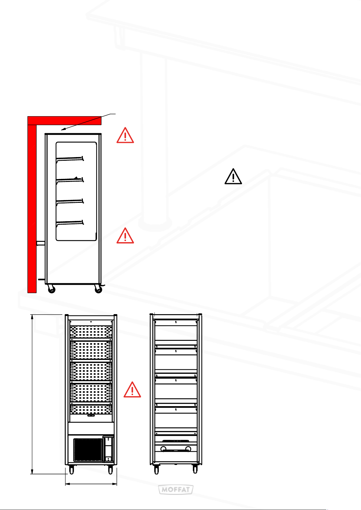
To ensure the satisfactory operation and optimum eciency of this
unit, it is imperative that the ambient room conditions where the units
are being used do not exceed a room temperature of 25°c or exceed
a relative room humidity of 60%. Do not install units where there is high radiated heat,
e.g. direct sunlight, room heaters, or bright spot lights. Do not install units in draughty
conditions where the air movement is greater than 0.2mtr/sec.
(e.g. near doors, windows, air conditioning units or fans]
Should conditions exceed the above, the display units may not maintain food temperatures at the
required levels. E & R Moat cannot accept responsibility for the performance of the units being
used in extreme conditions.
Moving Position.
Prior to moving the unit, it is essential to isolate and disconnect the power cord from the wall socket. This
precautionary measure helps prevent any electrical hazards during the repositioning process. Additionally, it is
important to stow the electrical power cord properly to avoid any potential damage while moving the unit.
Furthermore, it is crucial to note that the units are not designed to pass over ledges or obstacles. Care should be
taken to ensure that the wheels can move freely without any obstructions. It is also important to ensure that the
wheels never come into contact with the power cord, as this can cause damage to the cord and pose a safety risk.
By following these guidelines, the unit can be moved safely and without any unnecessary complications.
5
3: General Installation
1. Remove all packaging & plastic coatings from the appliance.
2. Check for any damage.
3. Assemble all parts, including shelves,etc.
4. Ensure all switches are in the OFF position.
5. Connect the mains input plug to the socket outlet.
6. Turn on and check the unit is functioning correctly.
Table top units are heavy, an adequate amount of personnel (or lifting gear if available)
should be used, to avoid any risk of injury or damage to the unit.
Ensure the power cable is not damage or trapped under the feet when moving into the
final position.
Table top models:
To ensure the safety of both the unit and personnel, it is important to make appropriate arrangements for lifting
and positioning. This will help minimize the risk of damage or injury. Sucient personnel should be available to
handle each unit, while adhering to the health and safety policies of the company or site. By following these
measures, potential hazards can be mitigated eectively.
To maintain the proper functioning of the equipment, it is crucial to keep it in a vertical orientation at all times.
Once the unit has been placed in the desired location, the brakes should be secured to prevent any unintentional
movement. This will help ensure the stability and integrity of the equipment, reducing the risk of damage or
disruption to its operation.
Free-standing mobile models:
To prevent any movement of the unit once it is placed in the desired location, it is
recommended to utilize the castor brakes that are fitted on free-standing models.
These castor brakes are specifically designed to secure the unit in place. They are
located on the front of the unit and should be applied to ensure stability and prevent
any unintended movement. By engaging the castor brakes, the unit will be eectively
immobilized, reducing the risk of accidents or damage.
General all models:
6
4: Operation Heated Models
Heated display units are designed to keep pre-heated food at a regulated serving temperature and are suitable for
the display of most types of hot food. Designed with individually controlled shelves maintaining a safe and compliant
temperature within. Each level is fully adjustable between 60°C and 90°C.
Control are positioned on the front behind a slide up perspex window.
The controlled air temperature is factory set to operated at 85°C.
These units are not designed to cook or heat up cold food.
The display zones have low height perspex screens positioned top and bottom these screens must
be fitted. Food held in the display will not maintain proper temperature if the screens are removed
Each individual display level is controlled independently with a dedicated on / o switch and digital display.
There is one green illuminated on / o switch for the full vertical display lights.
1. Setting the black shelf zone switch to "I" turns power on.
2. The zone digital display will illuminate and show the current shelf temperature.
3. The shelf zone area will start to heat up. (The standard factory setting is 85°C.)
4. Switch on the green switch to illuminate the display area.
5. Setting the black shelf zone switch to "O" turns power o.
The shelf zones will take approximately 45min to reach operating temperature.
Do not load any food products into the shelf zone before the set temperature is reached.
Set each zone to the desired display temperature.
The individual zones can be used heated and set at dierent temperatures or left unheated in an ambient condition.
The food to be displayed must be cooked and at the proper temperature before placing into
the unit. Transfer hot food immediately into appropriate packaging and place directly into the
display zone. Follow local regulations and check food temperatures are maintained regularly.
NOTE : The temperature displayed on each control is an indication of each operating zone.
Not the core temperature of the food in the zones
7
Adjusting the temperature:
The minimum and maximum temperature limits are factory set, the controlled temperature of each zone can be set
anywhere between the limits 60°C and 90°C.
To view the set temperature of a zone.
• Press the "SET" button twice.
To change the temperature of a zone.
• Press and release the "SET" button once SET will be displayed on the screen.
• Press and release the "SET" button a second time, the current set-point temperature will be displayed.
• While the current set point is displaying, use the "up or down arrow" buttons to change temperature.
• The up arrow button increases the desired set temperature the down arrow reduces the temperature.
• When the required setting is displayed press and release the set button to save that temperature.
• Leave the control alone and after 15 seconds the current zone temperature will be displayed.
Alternatively press the power button to save the setting.(top right hand button)
4: Operation Heated Models
Control panel No 1:- all heated models have this type.
Control panel No 2:- all heated 3 shelf models have control panel No 1 and control panel No 2
Control panel No 3:- all heated 4 shelf models have control panel No 1 and Control panel No 3
No 1
No 2
No 3
8
Merchandising:
"E&R Moat Ltd acknowledges that dierent products have varying display time requirements based on their
core temperature. It is crucial to consider these requirements to ensure optimal quality and safe temperature for
consumption. However, E&R Moat Ltd does not accept responsibility for any variances or loss of quality that may
occur due to product dierences."
"All items placed in the display should adhere to the correct packaging or container requirements, following in-store
procedures and best practices. If any products are found to be in damaged packaging, it is important to promptly
remove them from the equipment and clean the area as soon as possible."
Do not block any internal or external air vents.
4: Operation Heated Models
Legal requirements mandate that all products displayed for an extended period within a
heated display area must be periodically probed during trading.
This is to ensure that the core temperature of the product remains above the legal holding
temperature set by the local authority. For specific instructions on how to conduct product
probing, please refer to the in-house operations manual.
To maximize the shelf-life of a particular food product at a safe temperature, it is prudent to enter the product into
the holding unit while it is as hot as possible. This practice helps to maintain the product's quality and safety standards
for an extended period
The equipment is not intended to actively increase the temperature of the products. Instead, the products naturally
cool and regulate their temperature over the course of the display period to maintain good quality. It is crucial to
ensure that the initial core temperature of the products is as high as possible to maximize the display time. Regardless
of the entry temperature, the product will gradually decrease in temperature during its display time. However, a lower
entry temperature will result in a shorter display time.
.
E&R Moat Ltd does not assume responsibility for any variances or loss of quality that may
arise as a result of product dierences or poor display and merchandising methods.
Calibrated probes should always be used to probe and record food temperatures.
9
Refrigerated Unit Venting
When installing these refrigerated units, allowances must be made for air venting.
It is crucial that there is an unrestricted air flow through the under slung compressor and condensing coil.
Proper venting must be provided ensuring cool air from the room can be pumped in through the condensing coil and
out the other side.
The hot air blown out from the opposite side ‘must not’ be allowed to be sucked back through.
Blocked vents will cause reduced eciency and lead to malfunction
A clear air space of at least 100mm
must be left between the unit and the rear wall
‹‹AirFlow
‹‹ AirFlow
Warning
A clear space of 600mm
must be left in front of this unit
5: Installation Conditions Refrigerated Models.
600
1858
When a chilled unit is to be placed next to a
heated model, a clear space of 50 mm must
be left between the units.
50mm
Minimum
10