© Air Techniques, Inc. Copyright 2012 •P/N H5247, Rev. D - November 2020
1295 Walt Whitman Road |Melville, New York 11747
Phone: 800-247-8324 |Fax: 888-247-8481
Website: www.airtechniques.com
12. Using a #2 Phillips screwdriver, remove the three screws securing the top panel of the replacement power module. Remove
the panel and set aside.
13. Install the replacement Power Module Assembly to the pump chassis by checking for proper orientation and carefully
lowering the assembly onto the corresponding installation space. Secure the power module to the chassis as follows.
a. Install two screws and washers removed by step 8 into the corresponding screw holes on the
right side of the pump chassis as shown by Detail 1. Tighten using a #2 Phillips screwdriver.
b. Install the screw removed by step 10 above into the corresponding screw hole on lower left of
the power module as shown by Detail 3. Tighten using a 5/16 inch nut driver.
c. Install the top panel removed by step 12 and secure with three screws.
d. Install the replacement front panel (See Detail 2) and secure with four screws.
14. Slide the harness assembly into the electrical connection box and install the strain relief nut. Connect the black, red and
white harness wires to the electrical connection box wires listed below corresponding to the module being replaced.
V3 and V5 Connections V7 Connections
Black harness wire to connection box wire. T1 Red Black harness wire to connection box wire T1 Blue
Red harness wire to connection box wire T2 White Red harness wire to connection box wire T3 Orange
White harness wire to connection box wire T3 Blue White harness wire to connection box wire T2 White
15. Insert the green with yellow stripe ground wire onto the ground screw and tighten using a #2 Phillips screwdriver.
16. Place the cover on the connection box making sure that the rubber gasket is properly aligned. Install four screws and secure
with a #2 Phillips screwdriver.
17. Connect the CAT-5 cable into the RJ-45 connector plug.
18. Connect the black, white and green with yellow stripe wires of the handy box to facility input power as shown by the Facility
Power Connection for MOJAVE Pump illustration above. Close and secure the cover of the handy box.
Power Module Reshipment Packaging
Repackage the power module to return it to the factory for evaluation. Use the original or similar packing material that would
provide adequate coverage and protection of the module during shipment.
7. Disconnect the black, white and green with yellow stripe wires of the
handy box connecting the power module to facility input power.
8. Using a #2 Phillips screwdriver, remove the two screws and washers from
the right side of the pump chassis as shown by Detail 1.
9. Using a #2 Phillips screwdriver, remove the four screws securing the
front panel as shown by Detail 2. Remove the panel and set aside.
10. Using a 5/16 inch nut driver, remove the screw from the lower left of the
power module as shown by Detail 3.
11. Remove the faulty power module from the pump chassis by carefully
lifting it up and away. Install the front panel removed by step 9 and set
the power module aside for reshipment to the factory.
Facility Power Connection for MOJAVE Pump
BLACK
WHITE
Power Cable
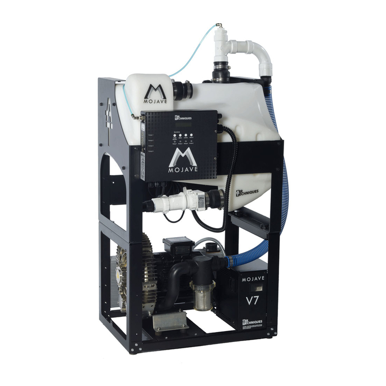
V3, V5 and V7 Power Module Assembly Replacement
Detail 1
Detail 2
Detail 3
V3, V5 and V7 MOJAVE
Vacuum Pump
GREEN YELLOW
STRIPE


