Molpir BBA54 User manual

Date: 15/07/2011 Page 1 / 9
NU
_
BBA54
_
001_
15072011_EN
D
DI
IG
GI
IT
TA
AL
L
S
ST
TE
ER
RE
EO
O
A
AM
MP
PL
LI
IF
FI
IE
ER
R
Index
1 Technical specifications
2 Operatin without the keypad
2.1 Power-on and off
2.2 In uts / Functionality
3 Operatin with the keypad
3.1 Power-on and off
3.2 In uts / Functionality
4 Connections
5 Dia rams of connection
1 + volume +
2 - volume -
3 RADIO select radio + ower-on for am lifier
4 VIDEO select radio + ower-on for am lifier
5 OFF am lifier off
6 MK1 micro hone 1 o erating light
7 MK2 micro hone 2 o erating light
8 GAIN - reduce gain
9 GAIN + increase gain
10 LED LED light
Ord. code: BBA54 / BBA54-12

Date: 15/07/2011 Page 2 / 9
NU
_
BBA54
_
001_
15072011_EN
General Features
A new conce t Digital Stereo Am lifier for vehicles, with significant technological innovations. All
functions are controlled by a micro-controller. Audio in uts (Radio-Video) and volume control. It
may be connected to any model/brand of Radio-Ta e/CD layer, which it also su lies ower
voltage to. Power-on for video system.
Two micro hone in uts with inde endent volume control and riority over all other sources. RS485
dual serial ort (interfaceable with CAN systems) to integrate into the vehicle devices and to
dialogue with different B&B devices. Can be cascadelinked to more am lifiers to create different
listening zones. Com act, versatile and easy to install. Works inde endently, connected to other
(B&B) am lifiers or with the (BBT54) a ro riate command key ad which enables direct source
selection and volume adjustment. Its small size means it fits easily into any art of the vehicle.
Caution
It is recommended to carefully read through the instructions, rior to setting this device in
o eration; a thorough understanding of the basics means an easier utilization of this device.
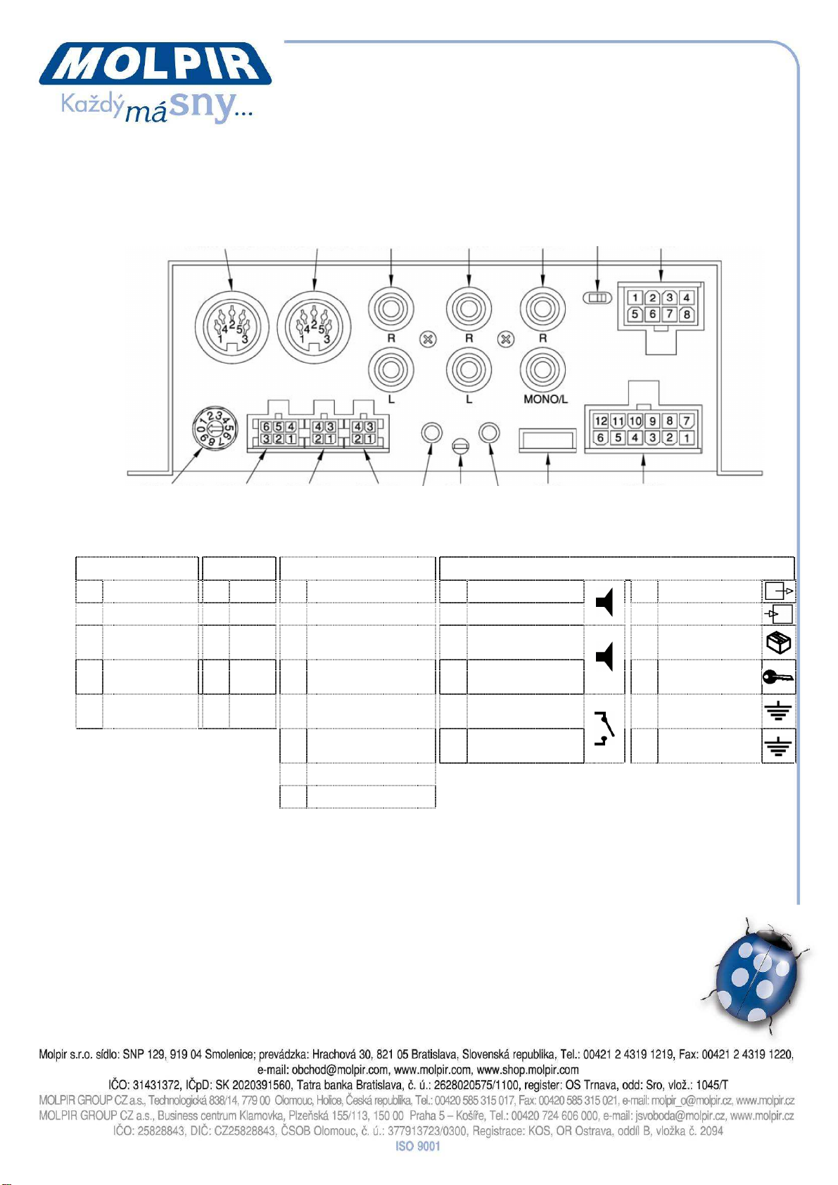
Please, follow the instructions to carry out the “BBA54” am lifier connections:
cha ter 4 CONNECTIONS
cha ter 5 DIAGRAMS OF CONNECTION
2 Operatin the BBA54 and BBA54-12 without the keypad
When ower is su lied the am lifier (BBA54 or BBA54-12) goes into standby mode and
su lies ower to the connected radio (Radio-Ta e/CD). By su lying voltage to the REM-RADIO
(switching on the radio) or REM-VIDEO (switching on the video system) or activating the
micro hones (MK1-MK2), the am lifier switches on. It is ossible to adjust the gain of each active
source individually. Adjustments remain in the memory even when the su ly voltage is switched
off. The REM-VIDEO has riority over the REM-RADIO, MK1 and MK2 have recedence over both
of them and MK1 has riority over MK2. In the absence of these commands, the am lifier returns
to standby.
2.1 Power-on and off
REM-RADIO (switching on the radio), REM-VIDEO (switching on the video system) or with
MIKE1/MIKE2 being active, the am lifier is switched on. In the absence of these commands,
standby mode is restored.
2.2 In uts/Functionality
RADIO: in ut for Radio -Ta e/CD
On switching on, the radio (Radio-Ta e/CD) su lies voltage (REM-RADIO) to contact no. 2 of the
“RADIO PW” connector of the determining am lifier: source on and source selection.
VIDEO: in ut for video system audio
Voltage (REM-VIDEO) su lied to contact no.10 of the “POWER” connector determines: switching
on monitors, am lifier and source selection. The VIDEO in ut has riority over the RADIO.
Mikes: The am lifier is rovided with two mike in uts (MK1-MK2) with riority over
all other sources, mikes are switched on with their own switch, and are
not de endent from the am lifier status (on or off).

Date:
15/07/2011
Page 3
/
9
NU
_
BBA54
_
001_
15072011_EN
Gain adjustment: Volume adjustment (in this configuration) de ends on the sources connected to
the am lifier. However, it is ossible to set the desired gain for each active source, by using the
(gain + or gain -) buttons on the am lifier. The red LED flashes during the adjustment hase. The
gain values set remain in the memory even if the ower is removed from the am lifier.
RS485 Serial: The RS485 dual serial ort (MODBUS-RTU rotocol) allows the am lifier (master) to
dialogue with all B&B devices and with any other systems in existence. The eri heral units
(slaves) identification is determined by the osition of the decimal uniselector on board all B&B
equi ment.
Just assign a number (1÷7) to each slave. Please, note that the number “0” is assigned to the
master.
3 Operatin the BBA54 and BBA54-12 with the keypad
When ower is su lied the am lifier (BBA54 or BBA54-12) goes into standby mode and
su lies ower to the connected radio (Radio-Ta e/CD). By ressing the relevant button for the
required source (RADIO or VIDEO) or by activating the micro hones (MK1 or MK2), the am lifier is
switched on (MK1 has riority over MK2). In this mode it is ossible to adjust the volume of each
active source individually. Adjustments remain in the memory even when the su ly voltage is
switched off. To turn off the am lifier, ress the OFF button, which restores it to standby mode.
3.1 Power-on and off
Select: Radio or Video to ower-on the am lifier. The corres onding key will change color from
reen to red, the OFF esc one will change from red to reen. Press the OFF key to ower-off the
am lifier.
3.2 In uts/Functionality
RADIO: in ut for Radio-Ta e/CD.
The am lifier su lies ower to the connected radio. Volume control is effected by ressing the
buttons + or -, and remains in the memory even if even if the ower is removed from the
am lifier.
VIDEO: in ut for video system audio.
The am lifier controls the on/off switch of the monitors. Volume control is effected by ressing the
buttons + or -, and remains in the memory even if even if the ower is removed from the
am lifier.
Mikes: The am lifier is rovided with two mike in uts (MK1-MK2) with riority over all other
sources, mikes are switched on with their own switch, and are not de endent from the am lifier
status (on or off). Volume control is effected by ressing the buttons + or -, and remains in the
memory even if even if the ower is removed from the am lifier.
RS485 Serial: The RS485 dual serial ort (MODBUS-RTU rotocol) allows the am lifier (master) to
dialogue with all B&B devices and with any other systems in existence. The eri heral units
(slaves) identification is determined by the osition of the decimal uniselector on board all B&B
equi ment.
Just assign a number (1÷7) to each slave. Please, note that the number “0” is assigned to the
master.

MICROPHONE 1
MICROPHONE
2
AUDIO
OUT
RADIO
PRE-IN
AUDIO
PRE-IN
MONO-STEREO
VIDEO SELECTOR
RADIO
SELECTOR
RS485
BBT54 IN
RS485 1
RS485 2
GAIN
-
GAIN +
LED
FUSE
POWER
4
CONNECTIONS
Date: 15/07/2011 Page 4 / 9
NU
_
BBA54
_
001_
15072011_EN
MICROPHONE 1-2
RS485 1-2
RADIO
POWER
1
MICROPHONE +
1 GND
1 GND
1 LOUDSPEAKER L+
4 REM-OUT
4
MICROPHONE -
2 GND
2 REM-IN RADIO
2 LOUDSPEAKER L-
10
REM-IN VIDEO
2
SWITCH
3 B
3 LOUDSPEAKER-IN L-
7 LOUDSPEAKER R+
5 +VDC IN (+30)
PERMANENT
5
SWITCH
4 A
4 LOUDSPEAKER-IN R-
8 LOUDSPEAKER R-
11
+VDC IN (+15)
IGNITION KEY
3
NC
5 +12V OUT (+30)
PERMANENT
3 VIDEO ON SWITCH
6 GND
6 +12V OUT (+15)
IGNITION KEY
9 VIDEO ON SWITCH
12
GND
7 LOUDSPEAKER-IN L+
8 LOUDSPEAKER-IN R+

Date:
15/07/2011
Page 5
/
9
NU
_
BBA54
_
001_
15072011_EN
5
DIAGRAMS OF
CONNECTION
BBA54-12 12V

Date:
15/07/2011
Page 6
/
9
NU
_
BBA54
_
001_
15072011_EN
BBA54 24V

Date:
15/07/2011
Page 7
/
9
NU
_
BBA54
_
001_
15072011_EN
BBA54-12 12V + BBT54

Date:
15/07/2011
Page 8
/
9
NU
_
BBA54
_
001_
15072011_EN
BBA54 24V + BBT54

Date: 15/07/2011 Page 9 / 9
NU
_
BBA54
_
001_
15072011_EN
This manual suits for next models
1
Table of contents
Popular Amplifier manuals by other brands

EAW
EAW CXA160 / CXA80 instruction manual

Marantz
Marantz PM17A/F1N Service manual

Kicker
Kicker MX350.4 quick guide

McIntosh
McIntosh MA6500 brochure

STK Professional Audio
STK Professional Audio VS-25 owner's manual

Extron electronics
Extron electronics Two Output 13W3 Sun and SGI Distribution Amplifier 13W3... Specifications