STK Professional Audio VS-25 User manual
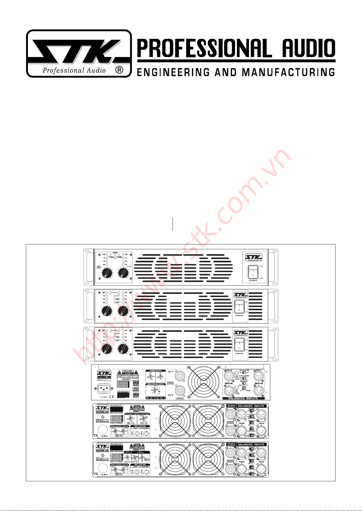
VS-25
VS-34 Power Plus
VS-40 Power Plus
2 채널 디지털 파워 앰플리파이어
사용설명서
2 Channel Digital Power Amplier
OWNER'S MANUAL
(MONO/BRIDGE)
VS-34Power Plus
STEREO DIGITAL POWER AMPLIFIER
CH.A CH.B
VS-40Power Plus
STEREO DIGITAL POWER AMPLIFIER
CH.A CH.B
(MONO/BRIDGE)
VS-25
STEREO DIGITAL POWER AMPLIFIER
BRIDGE Power Plus
POWER CONSUMPTION
1530 VA
1
/
3
POWER
1296Wx2 / 4 ohms
780Wx2 / 8 ohms
1296Wx2 / 4 ohms
780Wx2 / 8 ohms
2300W/ 8 ohms(Bridge)
CH2
CH2
VS-25
http://www.stk.com.vn
2
1. Introduction
l
제품 소개
VS-25 / VS-34 Power Plus / VS-40 Power Plus
2 Channel Digital Power Amplier
2 채널 디지털 파워 앰플리파이어
Table of Contents
l
목 차
1. Introduction l 제품 소개........................................................................................................................................
2
2. Important Safety Instructions l 안전을 위한 주의 사항.....................................................................
3
3. Panel Description l 각 부의 명칭 ....................................................................................................................
5
4. Connecting Your System l 올바른 설치 방법 .........................................................................................
10
5. System Hookup Diagram l 시스템 연결 구성도.....................................................................................
16
6. Block Diagram l 회로의 구성도.........................................................................................................................
18
7. Specications l 제품 규격...................................................................................................................................
20
8. Warranty Information l 제품 보증에 대해서 ..............................................................................................
22
STK VS-25/VS-34/VS-40 디지털 파워 앰프는 제한
없이 다양한 용도에 대응할 수 있도록 디자인 되었으며
고전압 8옴 출력과 고전류의 4옴 혹은 2옴 출력에 유연
하게 동작합니다. 울트라급의 낮은 노이즈와 최고음질의
저왜율 그리고 고효율의 H클래스 출력단, 어떠한 과도
입출력도 컨트롤하는 CTLL 레벨 리미터로 구성되어 있
습니다. 강력한 Professional Sound 시스템의 설치와 사
용을 위해 설계된 최신 성능의 고품질 제품입니다.
VS-25/VS-34/VS-40의 차별화된 특징은 초경량 고출
력의 디지털 스위칭 파워 서플라이라는 점입니다.
VS-25/VS-34/VS-40은 최악의 조건하에서도 문제없
이 동작하기 위해 고효율의 가변 속도 형 팬 냉각방식을
채용하고 있습니다. 또한, LED 표시등을 적용한 멋진 전
The STK VS-25/VS-34/VS-40 a high outputs, 2CH
power amplifier state-of-the art performance designed
for professional use sound reinforcement and installation
use.
The products responsible to high voltage 8 ohm
outputs and high current 4 ohm or 2 ohm outputs,
have the H class output stage for high efcient thermal
capacity and super clean THD sound with STK CTLL
over level limiter control circuits. These advanced high
quality technology products are mainly for powerful
Professional sound systems. A distinguishing feature of
the VS Series Ampliers is the Digital switching power
supply that makes high powered performance with
http://www.stk.com.vn
3
면부는 제품의 동작 상태와 기능을 알기 쉽도록 설계되어
있습니다. 기존의 가치를 넘어서는 더욱 강력하고 정확하
며 신뢰할만한 성능을 제공하기 위해서 STK VS-25/VS-
34/VS-40 디지털 파워 앰프는 수년간의 연구를 거듭하
여 설계 되었습니다. 제품을 동작시키기 전에 이 사용설
명서를 꼭 읽어보시고 이해하시어 올바르게 제품을 사용
해 주시길 바랍니다.
extremely low weight possible.
The VS-25/VS-34/VS-40 feature oversized high
efcient heat sinks in a wind tunnel cooling system with
variable speed fans for trouble free operation under the
most adverse conditions. In addition, VS-25/VS-34/
VS-40 has attractive front panels with a full complement
of LEDs to monitor functions and performance level
conditions. While providing powerful, accurate and
reliable performance along with outstanding value, your
STK VS-25/VS-34/VS-40 power amplifier has been
designed for many years dependable service. Please take
the time to read this manual before operation so that
you fully understand the features and correct use of this
exceptional product.
1. 사용 설명서를 꼭 읽어주세요
제품을 사용하기 전에 본 설명서의 안전과 작동에 관한 모든 기능
설명들을 반드시 읽어 보십시오.
2. 사용 설명서를 잘 보관하세요
안전과 작동에 관한 설명은 나중에 참고하게 될 경우가 있으므로
잘 보관해서 유용하게 사용하십시오.
3. 주의 및 경고사항
사용 설명서에 나타나 있는 모든 주의사항들은 반드시 지켜야 합니
다.
4. 사용법을 지켜주세요
본 설명서의 사용법에 관한 모든 내용들은 반드시 지켜야 합니다.
5. 수분과 습기주의
제품은 물기 또는 습기가 많은 곳에 설치하면 감전의 원인이 됩니
다. (욕조, 세면기, 부엌, 세탁기, 젖은 바닥, 수영장의 풀 근처, 습
지 등)
6. 열주의
제품은 전열기구 혹은 열을 발생하는 그 밖의 기구들로부터 떨어진
곳에 설치되어야 합니다. 설치 전 반드시 주변을 확인하시어 건조
한 장소에 제품을 설치해 주십시오.
7. 전원주의
이 제품은 반드시 사용 설명서에 정해진 타입의 전원 또는 본체에
1. Introduction
l
제품 소개
2. Important Safety Instructions
l
안전을 위한 주의 사항
1. Read Instructions
All the safety and operating instructions should be read before
the appliance is operated.
2. Retain Instructions
The safety and operating instructions should be retained for
future reference.
3. Heed Warnings
All warnings on this appliance and in the operating
instructions should be adhered to.
4. Follow Instructions
All instructions should be followed.
5. Water and Moisture
This appliance should not be used near water- for example,
near a bathtub, sink, laundry tub, in a wet basement, near a
swimming pool, etc.
6. Heat
This appliance should be situated away from heat sources such
as radiators, heat registers, stoves, or other appliances (including
ampliers) that produce heat.
7. Power Sources
This appliance should be connected to a power supply only
of the type described in the operating instructions or as
marked on the appliance. If you are not sure of the type of
http://www.stk.com.vn

4
power supply to your home, consult your appliance dealer
or local power company. For appliances intended to operate
from battery power, or other sources, refer to the operating
instructions.
8. Polarization
If the appliance is equipped with a polarized alternating-
current line plug (a plug having one blade wider than the
other), this plug will t into the power outlet only one way.
This is a safety feature. If you are unable to insert the plug
fully into the outlet, try reversing the plug. If the plug should
still fail to t, contact your electrician to replace your obsolete
outlet. Do not defeat the safety purpose of the polarized plug.
9. Grounding
If the appliance is equipped with a 3-wire grounding-type
plug, a plug having a third (grounding) pin, this plug will only
t into a grounding-type power outlet. This is safety feature.
If you are unable to insert the plug into the outlet, contact
your electrician to replace your obsolete outlet. Do not defeat
the safety purpose of the grounding-type plug.
10. Power Cord Protection
Power supply cords should be routed so that they are not
likely to be walked on or pinched by items placed upon or
against them, paying particular attention to cords at plugs,
convenience receptacles, and the point where they exit from
the appliance.
11. Damage Requiring Service
Unplug this appliance from the wall outlet and refer servicing
to qualied service personnel under the following conditions:
a. When the power-supply cord or plug is damaged.
b. If liquid has been spilled, or objects have fallen into the
appliance.
c. If the appliance has been exposed to rain or water.
d. If the appliance does not operate normally by following
the operating Instructions. Adjust only those controls
that are covered by the operating instructions as an
improper adjustment of other controls may result in
damage and will often require extensive work by a
qualied technician to restore the appliance to its normal
operation.
e. If the appliance has been dropped or the cabinet has
been damaged.
f. When the appliance exhibits a distinct change in
performance-this indicates a need for service.
12. Servicing
Do not attempt to service this appliance yourself as opening
or removing covers may expose you to dangerous voltage
or other hazards. Refer all servicing to qualied service
personnel.
표시된 전원에 연결되어야 합니다. 만약 사용하려는 전원이 확실치
않을 때는 전원 기구 판매자나 전원 공급자에게 문의하세요. 공급
되는 전원이 축전지 형태이거나 다른 방식이라면 제품 사용을 피해
주세요.
8. 분극 플러그에 대한 주의
만약 전원기구가 극성이 있는 교류전원이라면(플러그 중 한 블레이
드가 다른 것에 비해 넓게 되어 있습니다.) 이 플러그는 오직 한 가
지 방법으로 전원 아울렛에 끼워져야 합니다. 이것이 안전한 모습
입니다. 만약 플러그를 올바르게 끼울 수 없다면 플러그를 빼고 다
시 시도해 보세요. 만약 그래도 안 된다면 전원 아울렛을 교체하도
록 전기 기사에게 문의하세요. 분극 플러그에 대한 주의사항을 반
드시 지켜주세요.
9. 접지 플러그에 대한 주의
만약 전원기구가 3선 접지 타입의 플러그라면 세번째핀(접지핀)을
가지고 있을 것입니다. 이 플러그는 반드시 접지 타입 전원 아울렛
에 맞게 끼워져야 합니다. 이것이 안전한 모습입니다. 만약 이 플러
그를 전원아울렛에 올바르게 끼울 수 없다면 전원 아울렛을 교체하
도록 전기기사에게 문의하세요. 접지 플러그에 대한 주의사항을 반
드시 지켜주세요.
10. 전원 코드의 보호
전원 공급 코드는 플러그, 콘센트, 그리고 본 제품과 연결되는 지점
들에 특별한 주의를 기울이면서 정확한 방향으로 꽂혀야 합니다.
그렇지 못한 경우에는 화재 및 제품 손상의 원인이 될 수 있습니다.
11. 제품 손상 수리 서비스
본 제품에 다음과 같은 경우가 발생했을 때, 전문가에 의해서만 수
리를 받을 수 있습니다.
가. 전원공급 코드 혹은 플러그가 손상되었을 경우.
나. 제품 안으로 이 물질이 떨어졌거나 액체가 스며들었을 경우.
다. 제품이 빗물이나 물에 젖었을 경우.
라. 제품이 정상적으로 작동하지 않을 경우 사용설명서에 나와
있는 내용들을 조정해 보세요. 사용 설명서 외의 내용을 조
정할 경우 더 큰 고장의 원인이 될 수 있습니다.
마. 제품이 바닥에 떨어졌을 경우나 본체에 손상이 갔을 경우.
바. 제품이 작동 시 서비스를 필요로 하는 두드러진 변화를 보일
경우.
12. 서비스
직접 제품을 분해하거나 커버를 벗겨낼 경우 감전 등 여러 위험을
초래할 수 있습니다. 반드시 모든 서비스는 본사의 직원에게 문의
해 주세요.
2. Important Safety Instructions
l
안전을 위한 주의 사항
http://www.stk.com.vn

5
3. Panel Descriptions
l
각 부의 명칭
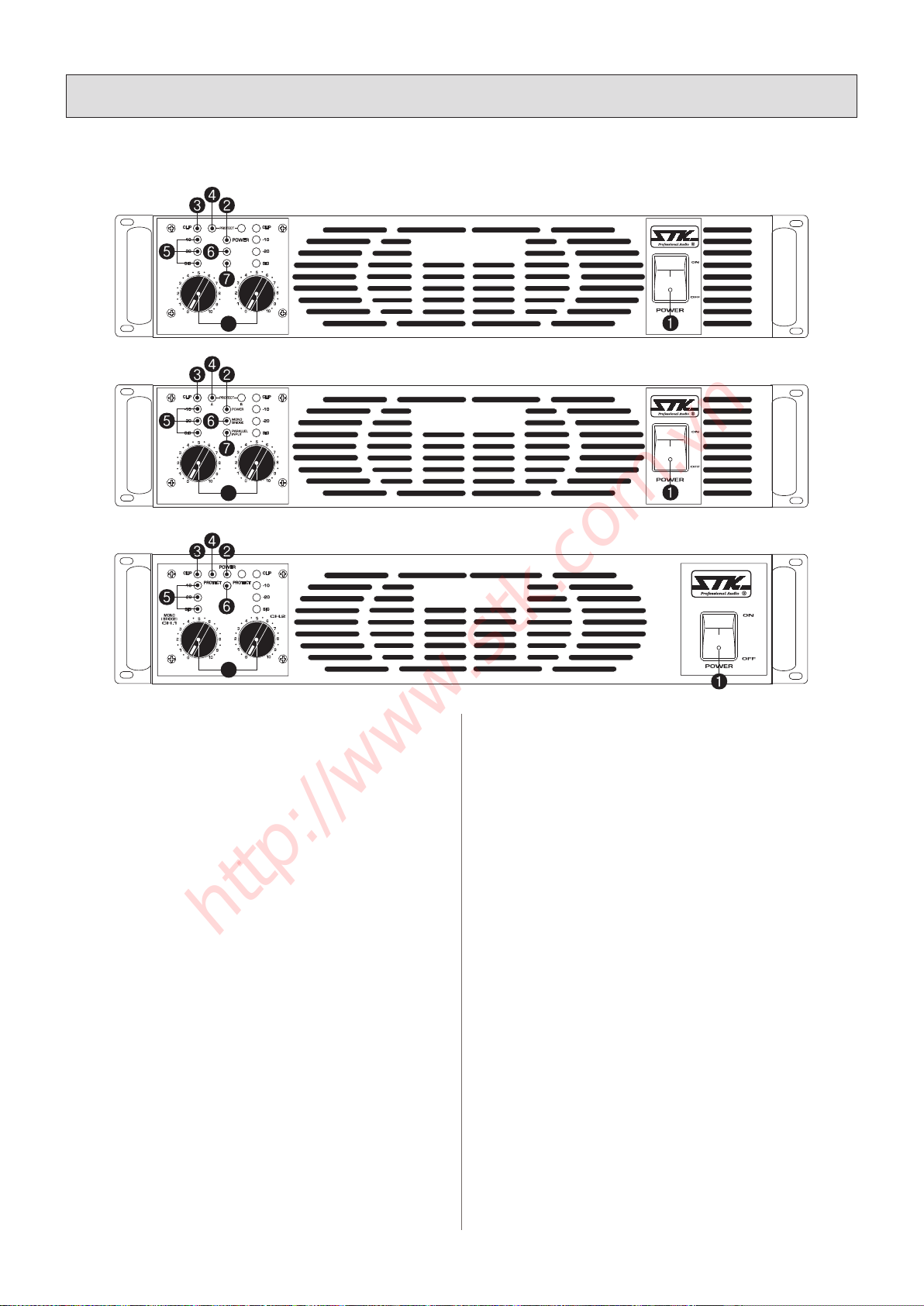
FRONT PANEL / 전면부
1. Power On/Off Switch
Before applying power, check all connections and turn down
the gain control. The "Soft Start" sequence start with the
POWER indicator LED at half brightness. A couple seconds
later the fan slow starts and the amplier cycles through
one second of protective muting, indicated by the CLIP and
protect LEDs glowing bright red. The POWER indicator
then changes to full brightness and the amplier is ready.
2. Power Indicator LED
3. Clip Indicator LED
a) Illuminates whenever the amplier is driven beyond
full power. The resulting distortion corresponds to the
brightness of the LED. Distortion that causes only brief
ashing may not be audible.
Note ; A clip LED for each channel indicates that your
signal level is so strong that there is distortion at the output
of that channel. While it is normal for the clip LED to
ash during program peaks, the LED should not remain
constantly lit during operation. If it does, most likely you will
hear the results in the form of distorted sound that can be
damaging to your speaker systems. In this case, reduce the
signal level by lowering the level control for the channel that
is clipping or reduce the level at the source. Note that when
using the amplier in the bridge mode, CH 1 clip LEDs of
the bridged channels will operate simultaneously.
1. 전원 스위치
전원을 공급하기 전에 모든 연결을 확인하고 볼륨을 최소로 하십시
오. 전원을 켜면“소프트 스타트”절차에 따라 전원표시등이 중간밝
기로 점등됩니다. 곧 냉각팬이 서서히 회전하기 시작하고 클립 표
시등과 보호모드 표시등이 붉게 켜지면서 약 1~2초 동안의 보호모
드로 들어갑니다. 그리고 전원표시등이 완전히 켜지면서 앰프의 모
든 기능이 동작대기 상태로 세팅됩니다.
2. 전원 표시등
3. 출력 신호 클립 상태 표시등
a) 앰프의 출력이 정격을 초과하여 출력에 디스토션 발생과 함께
켜집니다. 또한 순간적인 디스토션 발생은 미쳐 귀로 느끼지 못하
면서 LED만 간혈적으로 켜지게 됩니다.
참고 ; 클립 표시등은 각 채널에 입력되는 신호의 세기가 너무 강
해 출력이 최고치에 근접하는 것을 알려줍니다. 프로그램이 최고
조인 동안 클립 표시등이 깜박이며 동작 동안 지 속적으로 점등되
지는 않습니다. 지속적으로 표시등이 켜져 있다면 음질이 일그러
지는 것을 알 수 있을 것입니다. 이러한 일그러짐은 스피커 시스템
에 큰 손상을 가져옵니다. 이런 경우에는 일그러짐이 일어나는 채
널의 음량 조절기를 줄여 주시기 바랍니다. 앰프를 모노/브릿지
모드로 사용할 경우에는 CH 1의 클립 표시등이 동작하게 됩니다.
b)동작중 앰프의 열이 80도를 넘기시작하면 켜지기 시작합니다.
즉 정상 온도를 초과하기 시작하면 LED 가 켜지고 LED 가 꺼질
때까지 앰프 자체적으로 서서히 출력을 내리게 됩니다.
4. Protect(보호모드) 표시등
VS-40Power Plus
STEREO DIGITAL POWER AMPLIFIER
CH.A CH.B
MONO
BRIDGE
PARALLEL
INPUT
(MONO/BRIDGE)
A B
(MONO/BRIDGE)
VS-34Power Plus
STEREO DIGITAL POWER AMPLIFIER
CH.A CH.B
VS-25
STEREO DIGITAL POWER AMPLIFIER
BRIDGE Power Plus
8
8
8
http://www.stk.com.vn
6
3. Panel Descriptions
l
각 부의 명칭
스피커 케이블이 쇼트되거나 출력에 직류전압발생시 혹은 전원부
과전류일 때 혹은 기기가 과열되는 등의 보호회로가 동작되어야 할
상황이 발생할 경우 점등됩니다.
참고 ; 보호모드 표시등은 앰프 외부의 연결에 문제가 있거나 부 하
또는 온도, 그리고 내부의 기능에 문제가 생겼을 경우에는 지속 적
으로 점등됩니다.
문제 상황 발생 시 앰프는 자동으로 보호 모드 기능을 작동시킵니
다, 보호모드로 전환되면 앰프는 모든 동작을 멈추고 보호모드 표
시등을 동시에 점등시킵니다. 보호모드 표시등이 계속켜지면 앰 프
의 전원을 끄고 앰프의 모든 외부접속상태와 문제를 일으킬수 있는
조건들을 점검해야합니다(과열,과입력,전원전압변동,출력쇼 트,4
옴 미만 부하등). 그리고 문제를 일으킨 요소를 올바르게 바로 잡았
다면 앰프의 전원을 다시 켜주십시오.
만약 그럼에도 불구하고 보호모드 표시등이 켜진 채로 있다면 앰
프의 사용을 중단하시고 STK 고객 서비스 팀이나 영업사원을 통
해 앰프를 수리하십시오.
5. 입력 신호 레벨 표시등
SIG 표시등은 출력이 -33dB 지점에 도달하면 켜지기시작하며,
-20 표시등은 출력이 -20dB 에도달했을때 켜집니다. 그리고 -10
표시등은 출력 이 -10dB에 도달했을 때 켜집니다.
6. 브릿지 모드 표시등
채널 1과 채널2가 브릿지 모드 상태임을 나타냅니다.
브릿지 표시등은 앰프 후면부의 브릿지 스위치를 브릿지 모드에 위
b) The LED illuminates whenever the amplier is heat up
to 80 degree. The resulting temperature corresponds to the
brightness of the LED. And then the amplier to control
smoothly reduce output power until will not light of the
LED.
4. Protect Indicator LED
If protect conditions should occur, such as a shorting in a
speaker cable, DC of outputs, over current of power supply
or excessively high operating temperatures, this LED will
light and the amplier will stop operation until the condition
is corrected.
Note ; The protect LED will continue indicates that there is
a problem either in the amplier's external connections, load
or temperature conditions or its internal functions. If one of
these situations occurs, the amplier senses the problem and
automatically switches into its "protect mode." The protect
LED will light to warn you of the trouble and the amplier
will stop working. If this happens, switch off the amplier
and re check for the correct working conditions(over
heating,too high input,too high AC main voltage,output
short,under 4ohm load and). If you feel that you have been
able to correct the fault condition that caused the amplier to
go into the protect mode, restart the amplier. If the protect
LED remains lighting when attempting to resume amplier
operation, do not use the amplier.
FRONT PANEL / 전면부
VS-40Power Plus
STEREO DIGITAL POWER AMPLIFIER
CH.A CH.B
MONO
BRIDGE
PARALLEL
INPUT
(MONO/BRIDGE)
A B
(MONO/BRIDGE)
VS-34Power Plus
STEREO DIGITAL POWER AMPLIFIER
CH.A CH.B
VS-25
STEREO DIGITAL POWER AMPLIFIER
BRIDGE Power Plus
8
8
8
http://www.stk.com.vn

7
3. Panel Descriptions
l
각 부의 명칭
치시켰을 때 켜집니다.
앰프의 전원을 켜기 전에 항상 스위치가 올바른 위치에 있는지 확
인하시고 모든 스피커 연결을 정확하게 구성해 주십시오.
7. 페러렐 모드 동작 표시등 (출력 모노가 아님)
채널 1과 채널2의 입력신호가 페러렐 연결(병렬접속)상태임을 나
타냅니다(모노 브릿지 출력이 아님).
페러렐 표시등은 앰프 후면부의 페러렐 스위치를 parallel 모드에
위치시켰을 때 켜집니다, 파라렐 모드에서는 각각의 스피커는 반
드시 해당되는 채널의 앰프에만 연결해야합니다. 앰프의 전원을 켜
기 전에 항상 스위치가 올바른 위치에 있는지 확인하시고 모든 스
피커 연결을 정확하게 구성해 주십시오.
8. 음량 조절기
각 앰프 채널의 입력게인을 조절합니다. 브릿지 모드에서는 채널 1
만이 활성화 됩니다. 게인을 올리려면 조절기를 시계방향으로 내리
려면 그 반대 방향으로 돌립니다. 우수한 헤드룸으로 충분한 신호
증폭을 위해 레벨조절기는 가급적“5”위치 이상으로사용하세요.
Refer the amplier to an authorized STK service facility or
contact your dealer for help.
5. Signal level meter
The SIG indicator illuminates when the output signal exceeds
-33dB,and the -20 indicator illuminates when the output
signal exceeds -20dB, and the -10 indicator illuminates when
the output signal exceeds -10dB,
6. Bridge Mode Indicator LED
Shows when channels 1&2 are in the bridged mode. The
Bridge LED will light when you have set the rear panel
switch to the Bridge position for bridged operation. Always
make sure that this switch is in the correct position and that
all speaker connections have been made correctly for the
mode of operation you wish to use before powering up the
amplier.
7. Parallel Mode Indicator LED
Shows when channels 1&2 input signals are connected in
the parallel mode(not mono bridge output). The parallel
LED will light when you have set the rear panel switch to the
parallel position .In parallel mode, connect each speaker to
its own of the amplier. Always make sure that this switch is
in the correct position and that all speaker connections have
been made correctly for the mode of operation you wish to
use before powering up the amplier
8. Level Control Attenuators
Establishes the required input level for each channel of
Amp. In the bridge mode, only the channel 1 attenuator
is functional. Turn the level controls clockwise to increase
gain and counter clockwise to decrease gain. The level
control setting up to “5” range as normally for improve input
headroom.
http://www.stk.com.vn
9. Speakon Output Connectors
Separate NL4 connectors for CH 1, CH 2 speaker outputs.
Note : when making Speakon cables, be sure to connect the
loudspeaker wiring as shown on the chassis. Channel 1’s
Speakon provides 4 –wire (Ch1 +Ch2)connection : Channel
2’s Speakon provides 2-wire(Ch2 only) connection. Table
of Contents “(4) Connection Cables & Connectors”
provides Speakon connection reference.
Note ; Speaker connections by speakon jacks and it provides
a safe and reliable connection capable of transferring high
power signals if properly connected. To avoid ANY possible
shock hazard, the power amplier should be disconnected
from the AC power source before making any connections.
When connecting your speakers using speakon jacks method,
be sure to pay close attention to proper polarity. Although
connecting your speaker systems out of phase using the
wrong polarity will not damage your speakers, it will affect
the quality of sound. When using bare wire connections,
be sure that your connections are "clean." If any strands of
wire from one connector are allowed to touch the adjacent
connector, damage to your amplier and sound system could
occur.
10. XLR Inputs / Through Out Jacks
Low impedance, balanced inputs accept a male XLR
connector. / Accept a female XLR connector for parallel
connect to other inputs.
9. 스피콘 타입 스피커 연결부
스피커 출력 채널1과 채널2에 대한 NL4 방식 컨넥터(잭)입니다.
참고 : 스피콘 케이블을 연결할때에는 반드시 제품후면부에표시
된 연결 내용을 유의해야합니다. 즉 채널 1의 스피콘 출력 커넥터
는 모두 4개의(채널1+채널2)출력 와이어가 연결되어 있으며, 채널
2의 스피콘출력 커넥터는 2개의(오로지 채널 2출력)출력와이어 가
연결되어 있습니다.
목차“(4)의 커넥터와 케이블 연결”의 Speakon 컨넥터 연결에 대
한 내용을 꼭 지켜주세요.
참고 ; 스피커 연결은 speakon 짹에 의해 이루어지며 안전하고 믿
을 수 있게 연결이 잘 되어 있다면 완벽하게 높은 파워의 신호를 전
달합니다. 가능한 모든 사고를 예방하기 위해서 연결이 확실히 이
뤄지기 전에는 절대 전원을 연결하지 마십시오. 또한, 스피콘 방식
으로 스피커를 연결한다면 올바르게 극성을 연결하도록 주의를 기
울이십시오. 극성을 잘못 연결했음에도 불구하고 스피커에 손상을
입히지 않는다면 반드시 음질에 문제가 생길 것입니다. 베어 와이
어(연심투명선)를 사용하여 연결할 경우 간단하고 깔끔하게 연결이
잘 되었는지 확인해야 합니다. 만약 한 가닥이라도 접속단자에 인
접하여 단자를 건드리게 된다면 앰프에 손상을 입힐 것이며 다른
사운드 시스템에도 손상을 입히게 됩니다.
10. XLR 입력단자 / 입력신호 XLR 출력부
돌출형 XLR 컨넥터를 끼우는 낮은 임피던스, 밸런스드 입력단자
입니다. / 함몰형 XLR 컨넥터를 사용하며 다른 기기와 입력신호를
병렬 사용하게 합니다.
3. Panel Descriptions
l
각 부의 명칭
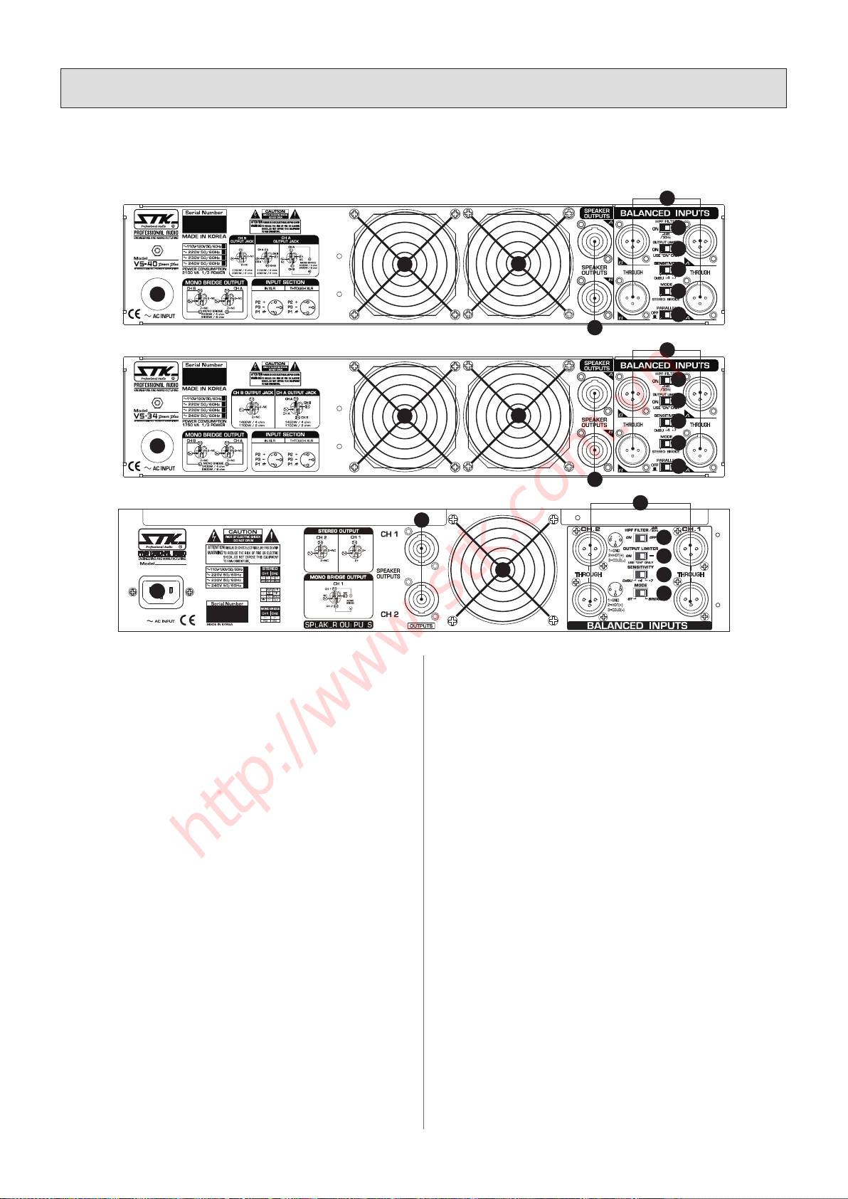
REAR PANEL SECTION / 후면부
POWER CONSUMPTION
1530 VA
1
/
3
POWER
1296Wx2 / 4 ohms
780Wx2 / 8 ohms
1296Wx2 / 4 ohms
780Wx2 / 8 ohms
2300W/ 8 ohms(Bridge)
CH2
CH2
VS-25
17
16 16
9
10
15
14
13
11
12
16
17
17
16 16
9
9
10
10
15
14
13
11
15
14
13
11
12
8
http://www.stk.com.vn

9
11. 모드 스위치 (스테레오-브릿지 )
Stereo 모드 ; 채널별로 서로 다른 입력신호를 넣으면 모든 입출력
은 각 채널별로 독립적으로 작동하게 됩니다.
Bridge 모드 ; 2개 앰프 채널을 하나의 싱글앰프로 콤바인시켜 2배
의 출력을 얻게합니다. 반드시 1번 채널 입력과 1 번채널 레벨콘트
롤만 사용하세요(자체적으로 1과 2 채널의 입력부가 이미 직렬 상
태로 접속되어집니다).브릿지 모드에서는 절대 채널 2의 입력은 사
용해서는 안됩니다.
12. 모드 스위치 (스테레오-파라렐)
파라렐 모드 세팅은 2 개 앰프의 입력을 1 개의 입력만으로 사용할
수 있게 해줍니다. 즉 한측 입력신호를 다른한측 입력부로 동시에
보냅니다. 파라렐 모드시는 양측입력에 절대 서로 틀린 입력신호
를 연결하지마세요. 또한 모든 각채널의 게인콘트롤과 스피커 출력
부는 독립적으로 작동됩니다. 채널 1 과 2 에는 반드시 1 개입력만
연결하세요.
13. 입력 감도(레벨)선택 스위치
앰프의 입력 감도를 3단계로 세팅할수 있습니다.
0dBu ;입력신호 레벨이 RMS 0.775V 일때 레벨 볼륨을 최대로 하
면 앰프의 최대출력을 공급할 수 있습니다.
+4dBu ; 입력신호 레벨이 RMS 1.227V 일때 레벨 볼륨을 최대로
하면 앰프의 최대출력을 공급할 수 있습니다
+7dBu ;입력신호 레벨이 RMS 1.734V 일때 레벨 볼륨을 최대로
하면 앰프의 최대출력을 공급할 수 있습니다
14. 스피커 보호 출력 클립 리미터
오디오 신호가 앰프의 출력회로의 허용 출력량을 넘어서면 파형의
최고점에서 클립상태가되면서 스피커 파손의 원인이됩니다. 출력
클립 리미터가 이것을 발견하면 빠르게 게인을 컨트롤하여 클립을
방지합니다 .필요시는 출력클립 리미터 스위치를 끌 수 있습니다.
고가의 스피커 시스템을 안전하게 보호하기 위해 스위치는 항상
“ON” 위치에 두고 사용하세요,
15.
입력 필터 (로우 컷 필터)
30Hz 이하의 신호를 커트해주는 저주파 필터입니다. 이는 서브 오디오
콘 모션을 제한함으로써 가청 주파수 영역에서의 스피커의 출력을 늘려
베이스 성능을 향상시킵니다. 각 채널의 필터는 슬라이드 방식으로
동시에 조절할 수 있습니다.
16. 통풍구
앰프의 출력과 내부온도가 올라가면 팬은 자동으로 고속 회전하여
앰프내부를 냉각시켜줍니다. 또한 랙 시스템으로부터 앰프 후면에서
전면으로 에어를 통과시키도록 되어 있어서 랙 내부의 온도를 억제시키는
역할도 합니다. 절대 통풍구를 막지 마십시오.
17. AC 메인전원을 연결하는 2.5mm 2 26A 정격 전선입니다.
(VS-34/VS-40)
전원 스위치가 꺼진 상태에서 연결해 주세요. 또한 전선을 접속하는 메인
전원 차단기는 반드시 제품의 소비전류에 적당한 것이어야 합니다.
220V-240V 국가 : 20A 이상 차단기
120V 국가 : 40A 이상 차단기
17. AC 메인 전원 접속부 (VS-25 해당)
AC 메인 전원을 연결하는 IEC표준형 전원입력소켓입니다.
참고 :전원 스위치가 꺼진상태에서 전원을 연결해주세요, 또한 전
원플러그를 접속하는 메인전원 콘센트규격은 반드시 제품의 소비
전류에 적당한 것이어야 합니다.
11. Mode Switch (Stereo-Bridge)
Stereo mode : Each channel remains independent, and each
channel may be used for a different signal.
Bridge mode : This setting combines both channels into
a single channel with twice the output voltage .Use only
channel 1’s input and level control (channel 1 and channel 2’s
inputs are internally connected in series). Do not use channel
2’ inputs when operating in Bridge mode.
12. Mode Switch (Stereo-Parallel)
The parallel setting connects both input together. One input
signal feeds both channels. do not connect different source
to both CH input. Each channel level control and speaker
connection remain independent. Use only one input to
channel 1&2, when operating in parallel mode.
13. input Sensitivity Switch.
3 position settings for input sensitivity as
0dBu ; RMS 0.775V input signal levels provide full power
output when the level control is maximum.
+4dBu ; RMS 1.227V input signal levels provide full power
output when the level control is maximum.
+7dBu ; RMS 1.734V input signal levels provide full power
output when the level control is maximum
14. Output Clip Limiter for Speaker protection
When the audio signal drives the amp’s output circuit beyond
its power capability, its clips, attening the peaks of the wave
form. The limiter detects this and quickly reduces the gain to
minimize the amount of overdrive. set to the “ON” as usual.
But you can switch it ON or OFF if necessary.
15. Input filter(Low Cut Filter)
The low-frequency (LF) lter rolls off signals below 30Hz .
This improves bass performance by limiting sub-audio cone
motions making more power available for the speaker rated
frequency range. The lter settings for both channels are
controlled together through the slide switch setting shown.
16. Cooling Air Port.
Air ows from the rack, into the back of the amplier,
and out of the front. This keeps the rack cool. The fan
automatically runs faster when the amp is working hard.
Do not obstruct air ow to this opening.
17. AC mains cable(2.5mm2 26A) for connect to AC
power. (VS-34/VS-40)
Turn off the AC power switch before conoonecting AC
power. Connect the AC mains cable to a suitable AC mains
circuit breaker.
220V - 240V area : More than 20A type circuit breaker.
120V area : More than 40A type circuit breaker.
17. AC Mains Connection (VS-25 Only)
Connect AC power to the IEC socket.
Note : Turn off the AC power switch before connecting AC
power. Connect the AC mains plug to a suitable AC mains
outlet.
3. Panel Descriptions
l
각 부의 명칭
http://www.stk.com.vn
10
4. Connecting Your System
l
올바른 설치 방법
CONNECTION CABLES & CONNECTORS
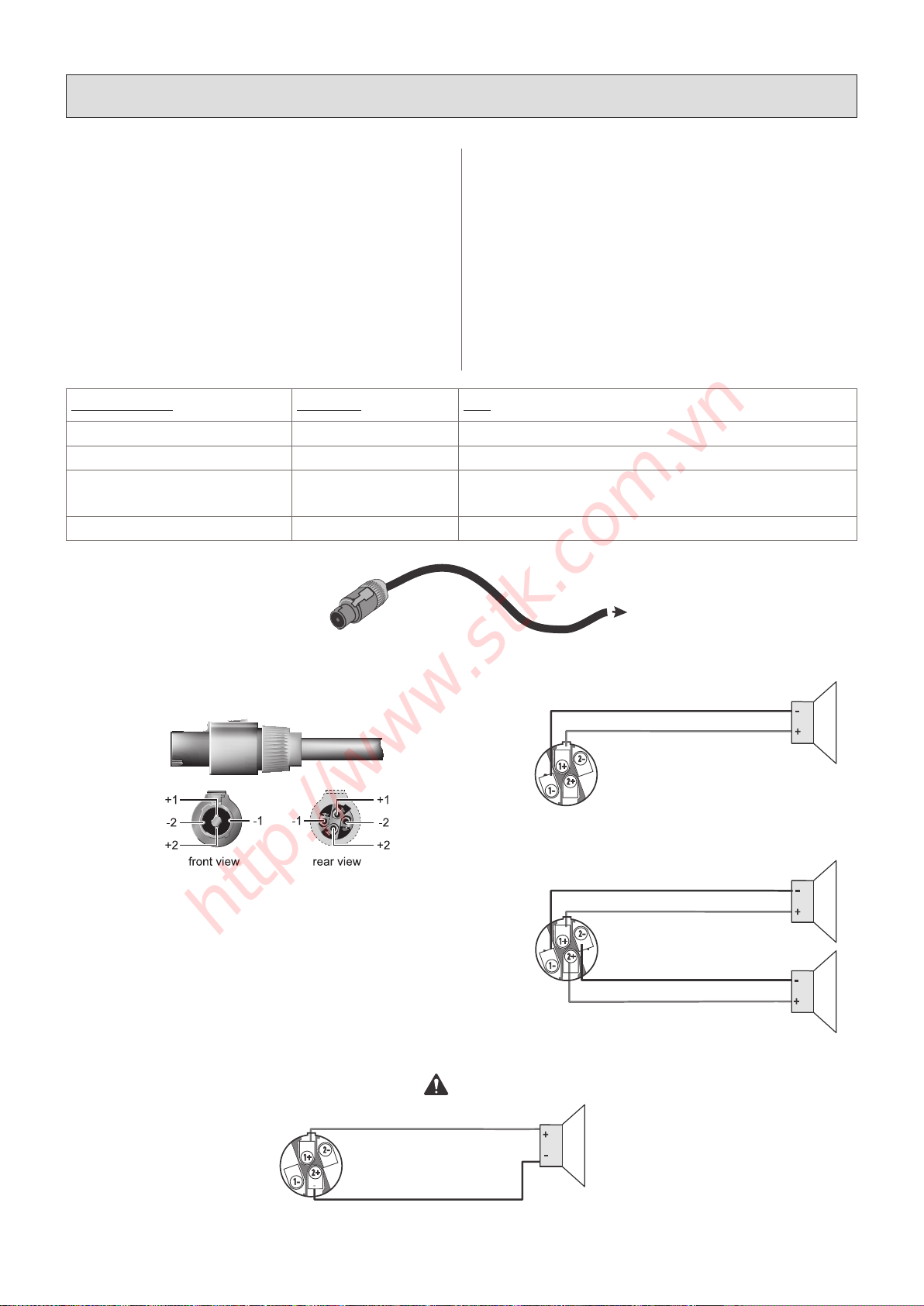
1. Speakon Connections
Speakon connectors are purpose-built for low voltage, high
current applications.
Each connector incorporates two pair of conductors, labeled
1+, 1-, 2+ and 2-. By convention, single signals are sent on
1+ and 1-. The second pair, 2+ and 2-, are used only if there
is a second unique signal present at the connector. When
attaching NL4FC mating connectors, be sure to insert
the connector to its full depth, then turn the connector
45°clockwise to lock it in place.
커넥터와 케이블 연결
1. 스피콘 연결
Speakon 컨넥터는 저전압 고전류를 위해 설계 되어있습니다.
각각의 컨넥터는 1+, 1-, 2+ 그리고 2- 로 표시된 2쌍의 컨덕터로
이루어져 있습니다.
첫번째 컨덕터에서 1+ 와 1-이 보내지고, 2+ 와 2-를 보내는 두
번째 컨덕터는 컨넥터에 두 번째 출력 신호가 있는 경우에만 쓰입
니다. NL4FC 컨넥터를 끼울 때에는, 컨넥터가 확실히 잘 끼워졌는
지를 확인하시고, 시계방향으로 45°돌려 컨넥터를 잘 고정시켜 주
십시오.
Output Function l 출력기능 Connector l 컨넥터 Pins l 핀
Speaker # 1 CH A 1+(Speaker +), 1-(Speaker -)
Speaker # 2 CH B 1+(Speaker +), 1-(Speaker -)
Speaker # 1, Speaker # 2 CH A Speaker # 1=1+(Speaker +), 1-(Speaker -)
Speaker # 2=2+(Speaker +), 2-(Speaker -)
Bridged Mono A CH A 1+(Speaker +), 2+(Speaker -)
Amplifier connection To loudspeaker
Two-wire, single-channel connection
Four-wire, two-channel connection
Bridge mode connection
NOTE! Ensure proper polarity when
connecting bridge mode output!
Amplifier connection To loudspeaker
Two-wire, single-channel connection
Four-wire, two-channel connection
Bridge mode connection
NOTE! Ensure proper polarity when
connecting bridge mode output!
Amplifier connection To loudspeaker
Two-wire, single-channel connection
Four-wire, two-channel connection
Bridge mode connection
NOTE! Ensure proper polarity when
connecting bridge mode output!
Amplifier connection To loudspeaker
Two-wire, single-channel connection
Four-wire, two-channel connection
Bridge mode connection
Speakon®Output Connector
NOTE! Ensure proper polarity when
connecting bridge mode output!
http://www.stk.com.vn
4. Connecting Your System
l
올바른 설치 방법
11
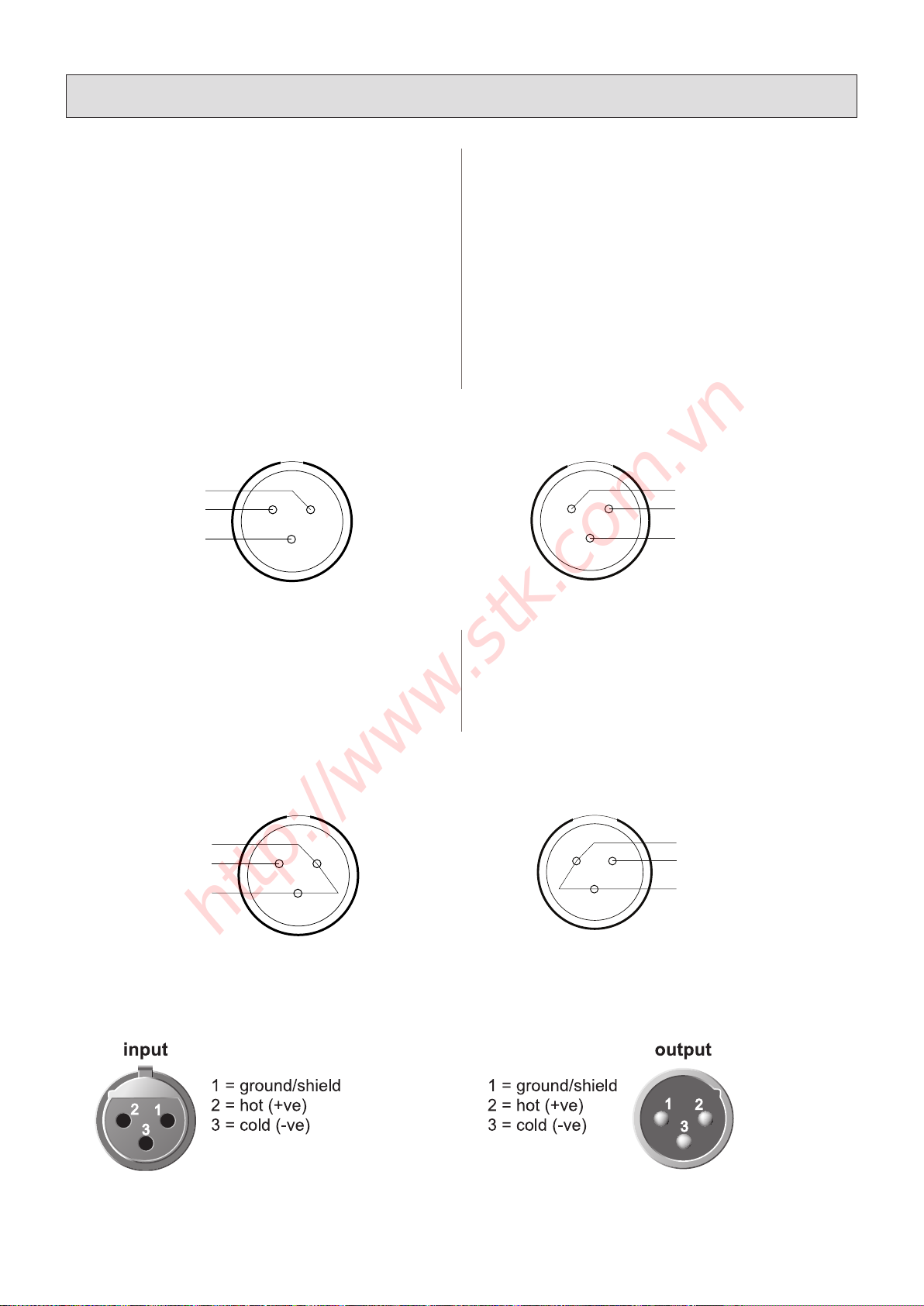
2. INPUT/INPUT THROUGH CONNECTIONS
The STK, VS-25/VS-34/VS-40 power ampliers are
designed to be as versatile as possible. The following
descriptions of the input and output connections are designed
to help you maximize the unit's potential.
1). BALANCED XLR Input Jacks / Through Jacks
Electronically balanced input accepts a standard XLR male
and female connector.
Pin1=ground, Pin2=hot or positive (+).
Pin3=cold or negative (-).
2). UNBALANCED XLR Input Jacks / Through Jacks
Electronically unbalanced input accepts a standard XLR male
and female connector.
Pin1=ground, Pin2=hot or positive (+).
Pin3=ground (-).
2. 입력신호 입출력 XLR 단자 연결
STK VS-25/VS-34/VS-40 파워 앰프는 가능한 다양한 응용이 가
능하도록 설계되었습니다. 다음의 입출력 연결에 대한 설명은 기기
의 활용을 극대화 할 수 있도록 도와줄 것입니다.
1). 밸런스드 XLR 입력 잭 / 입력신호 XLR 출력잭
전기적으로 밸런스드 입력신호 용인 표준규격의 XLR
돌출형과 함몰형 컨넥터를 연결합니다.
2). 언밸런스드 XLR 입력 잭 / 입력신호 XLR 출력잭
전기적으로 언밸런스드 입력신호 용인 표준규격의 XLR
돌출형과 함몰형 컨넥터를 연결합니다.
Female Type Input Jacks l 함몰형 입력잭 Male Type Through Jacks l 돌출형 입력신호 출력잭
1. GROUND
(shield)
2. HOT +
3. COLD -
12
3
1. GROUND
(shield)
2. HOT +
3. COLD -
1 2
3
Female Type Input Jacks l 함몰형 입력잭 Male Type Through Jacks l 돌출형 입력신호 출력잭
1. GROUND
(shield)
2. HOT +
3. GROUND
(-)
12
3
1. GROUND
(shield)
2. HOT +
3. GROUND
(-)
1 2
3
Female Type Input Jacks l 함몰형 입력잭 Male Type Through Jacks l 돌출형 입력신호 출력잭
http://www.stk.com.vn

4. Connecting Your System
l
올바른 설치 방법
12
A. 제품의 설치
본 기기는 19인치 표준 랙에 장착되도록 설계되어있습니다. 또한
안전을 위해 미끄럼 방지용 러버 풋이 함께 제공됩니다. 1대 이상
의 앰프를 함께 설치한다거나 다른 장비와 함께 설치하실 때에는
방열을 위하여 제품의 전면과 후면에는 공기의 흡입과 배출이 쉽도
록 막히지 않게 설치해 주십시오.
B. 제품 설치 시 주의사항
STK VS-25/VS-34/VS-40 파워 앰프는 외부 연결 장치의 손상이
나 오류에도 안전하도록 설계되어 있습니다. 그렇지만, 다음의 주
의사항들은 꼭 지켜주세요.
1. 안전을 위한 주의사항
본 사용 설명서의 3페이지에 나와 있는 안전을 위한 주의사항을 반
드시 읽고 숙지하시기 바랍니다.
본 제품이 물이나 다른 액체에 젖지 않도록 주의해 주십시오. 제품
이 물에 젖을 경우 반드시 전원 플러그를 전원으로부터 분리해 주
십시오. 그렇지 않으면 감전사고로 인해 상해를 입거나 사망할 수
있습니다.
2. 접지
만약 파워 앰프가 접지용 전원선과 플러그로 이루어진 세 개의 컨
덕터로 된 전원선을 가지고 있다면 반드시 그것과 적합한 전원 아
울렛에 연결하여야 합니다.
그라운드 리프트 어댑터를 사용하거나 플러그의 접지부를 없애고
사용해서는 안 됩니다. 부적절하게 접지 플러그를 사용하면 기기에
손상을 가할 수 있으며 다른 기기에도 위험한 문제를 초래할 수 있
습니다.
3. 라인 전압 주의
라인 전압이 ±5%를 넘지 않는 교류 전압을 사용해 주십시오. 이를
어길 경우에는 제품 보증 대상에서 제외됩니다.
A. MOUNTING
The VS-25/VS-34 and VS-40 powerplus are designed for
standard 19″rack mounting. In addition, the amplier is
provided with sturdy no-skid rubber feet for secure table
top or stacked operation. When rack mounting one or
more ampliers or when mounting in combination with
other equipment, be sure to allow adequate front and rear
ventilation to avoid possible heat related damage to your VS-
25/VS-34 and VS-40 powerplus or other rack mounted items
B. OPERATING PRECAUTIONS
Your STK VS-25/VS-34 and VS-40 powerplus power
amplier are well protected from any external faults.
However, we recommend following these common-sense
precautions:
1. Safety Instructions
Read and follow all of the safety warnings on page 3 of this
manual and on the separate safety precautions page enclosed
with the unit. Do not expose the VS-25/VS-34 and VS-40
powerplus to water or other liquids. Always unplug the unit if
water is present. Failure to do so can result in injury or death
from electric shock.
2. Grounding
If your power amplier is supplied with a three conductor,
grounded power cord and plug, connect the unit only to a
properly grounded mains outlet. Do not use a ground lift
adapter or otherwise attempt to defeat the ground on the
plug. Failure to properly ground the unit can result in damage
to the amplier or other equipment connected to it and
represents a dangerous safety hazard.
3. Line Voltage
Operate from AC mains not more than 5% above or below
the specied line voltage. Failure to comply may invalidate
your warranty.
4. Pre-Connection Caution
Always switch off the power and set all the level controls
to minimum before making any connections. This will
eliminate any chance of unexpected, loud audio transients
that could damage your speaker systems.
4. 연결 전 주의사항
제품의 연결 전에 전원을 끄고 모든 컨트롤 스위치를 최소로 하여
주십시오. 이는 스피커 시스템에 손상을 입힐 수 있는 연결 시 순간
적으로 예상치 못한 큰 소리를 내는 경우를 방지 할 수 있습니다.
AC 주전원 사용 전압
본 제품은 정격 AC전압을 사용하지 않으면 기기의 내
부 회로가 손상되거나 수명이 짧아지게 됩니다. 반드
시 제품 후면에 표기된 정격 전압을 지켜주세요.
http://www.stk.com.vn

C. 스테레오 동작
스테레오 모드에서는 4Ω의 기본적인 동작 구성을 권장합니다. 각
각의 채널은 입력 단자에서 받은 신호에 따라 각 스피커 출력단자
에 분리된 개별 신호를 내보냅니다.
VS-25/VS-34/VS-40은 스테레오 동작을 위해 두 개의 채널을 가
지고 있습니다. 다음 사용 방법을 잘 읽어 주십시오.
1. 병렬 모드 혹은 모노/브릿지 모드 스위치
후면부의 병렬 모드 혹은 모노/브릿지 모드 스위치를 스테레오 모
드에 위치시킵니다. 전원이 켜지면 병렬 혹은 모노/브릿지 표시등
이 꺼져있을 것입니다. 만약 표시등이 켜져 있다면 스위치가 잘못
위치한 것입니다. 스위치를 올바르게 위치시켜 주십시오.
2. 입력단자연결
전원을 끈 상태에서 입력 선들을 VS-25/VS-34/VS-40의 채널 1
과 2에 연결합니다.(절대 모노포닉 신호를 사용하지 마세요)
3. 스피커 연결
그림2를 참고해서 스피커 시스템을 연결해 주십시오. 각 채널당 스
피커의 합성 임피던스는 최소한 2Ω이 되어야 합니다. 각 채널 당
로드 임피던스가 2Ω(VS-25 : 4Ω) 이하일 때에는 본 기기가 동작
하지 않습니다.
4. Level Controls (음량 조절)
모든 볼륨 조절기를“0”에 놓고 전원을 켜 주십시오. 적정 수준의
입력신호를 입력하십시오. 다음으로 본 기기의 음량조정 볼륨을 원
하는 만큼 알맞게 조정하여 주십시오. 가능하면 앰프의 노이즈 영
역을 벗어나도록 입력신호의 노이즈율이 알맞은가를 확인해 주세
요.
클립 표시등이 켜질 때까지 원하는 만큼 가장 높은 수준까지 볼륨
을 조절해 보십시오. 클립표시등이 켜지지 않게 이러한 방식으로
볼륨을 조절하면 지속적으로 맑고 풍부한 음질을 유지할 수 있습니
다. 클립 표시등이 켜지면 앰프의 출력에 일그러짐이 발생한 것입
니다. 꼭 기억하세요.
C. STEREO OPERATION
The basic method of operation is recommended for 2 Ohm
or 4 Ohm applications. Each channel provides a separate
and discrete signal at the speaker outputs according to the
signal received at the inputs. The VS-25/VS-34 and VS-40
powerplus has two channels for stereo operation. Follow
these steps to use the amplier in this manner:
1. Set Parallel or Mono/Bridge switch
Set the Parallel or Mono/Bridge switch on the rear panel to
the stereo position. When the power is on, the Parallel or
Mono/Bridge LED on the front panel will not light. If the
LED illuminates, you have the switch in the wrong position.
Change the appropriate switch before continuing.
2. Input Connections
With the power off, connect your input source lines to
channels 1 and 2 on the VS-25/VS-34 and VS-40 powerplus.
3. Connect Speaker Systems
Connect speaker systems to speaker outputs as shown in
gure2. The total speaker load for each channel must be
at least 2 or 4 Ohms. The amplier will not operate at load
conditions lower than 2 Ohms(VS-25 : 4 Ohms) per channel.
4. Level Controls
With all level controls set to 0, switch the power on. Apply
a nominal signal to the inputs. The level of the input signal
should be about as high as you will ever need it to be. This
way, it will be as far above the amplier's noise oor as
possible, ensuring as excellent performance signal to noise
ratio. Adjust the input level controls for each channel to
achieve the desired maximum listening level or until the clip
LEDs ashes momentarily during program peaks, whichever
is lowest. Having set the levels in this manner will render
a clean signal at any level as long as the clip LEDs are not
constantly on. Remember, when the clip LEDs lights, there is
distortion present in the amplier's output section.
스피커 입력
스피커 입력
Use Left Stereo Signal Only
“좌”스테레오 신호만 입력하세요.
Use Right Stereo Signal Only
“우”스테레오 신호만 입력하세요.
FIGURE2. Speaker Connection Guide For Stereo Operation
그림2. 스테레오 동작 스피커 연결 가이드
4. Connecting Your System
l
올바른 설치 방법
13
http://www.stk.com.vn

14
4. Connecting Your System
l
올바른 설치 방법
D. 병렬 입력 모드 동작
병렬 입력 모드 동작에서는 양측 채널의 입력이 직접 서로 연결됩
니다. 그러나 모든 컨트롤과 스피커 연결은 통상적인 사용 상태입
니다. 절대로 양측 채널의 플러스 출력 단자를 함께 연결하지 마세
요.
1. 병렬 모드 스위치 (VS-34/VS-40 해당)
제품 후면의 병렬 모드 스위치를 병렬 모드에 위치시켜 주십시오.
전원이 켜지면 병렬 모드 표시등이 점등 됩니다.
만약 병렬 모드 표시등이 켜지지 않는다면 병렬 모드 스위치를 다
시 확인해 주십시오.
2. 입력 신호 라인
전원을 끈 상태에서 입력 신호 선을 VS-34/VS-40의 채널1에만
연결해 주십시오.
3. 스피커 출력
스피커 시스템의 연결은 그림3에 의해서만 연결해 주십시오. 스피
커 시스템의 총 부하 임피던스는 적어도 2Ω이상 이어야 합니다.
4. 볼륨 조절
모든 볼륨 조절기를“0”에 놓고 전원을 켜 주십시오.
그리고 입력 감도에 맞는 적정 수준의 입력신호를 입력하십시오.
다음으로 본 기기의 음량조정 볼륨을 원하는 만큼 알맞게 조정하여
주십시오. 이러한 방식은 우수한 신호 대 잡음비에 의해 앰프의 출
력을 기본 노이즈 플로어로부터 보다 우수하게 확보 할 수 있습니
다
클립 표시등이 켜질 때까지 원하는 만큼 가장 높은 수준까지 볼륨
을 조절해 보십시오. 클립표시등이 켜지지 않게 이러한 방식으로
볼륨을 조절하면 지속적으로 맑고 풍부한 음질을 유지할 수 있습니
다. 클립 표시등이 켜지면 앰프의 출력에 일그러짐이 발생한 것입
니다. 꼭 기억하세요.
D. PARALLEL INPUT MODE OPERATION
This method the inputs of both channels are directly
connected together, but all controls and speaker connections
as usual. Never connect the both positive output terminals
directly together.
1. Set Parallel switch (VS-34/VS-40 Only)
Set the switch on the rear panel to the parallel position, if you
wish to operate in the parallel input mode condition. When
the power is on, the Parallel LED on the front panel will
light. If the LED does not illuminate, you have the Parallel
switch in the wrong position. Change the appropriate switch
before continuing.
2. Input Source Lines
With the power off, connect your input source lines to
channels 1 only on the VS-34/VS-40.
3. Speaker Outputs
Connect speaker systems to speaker outputs as shown in
gure 3. The total speaker load for each channel must be at
least 2 ohms or higher.
4. Level Controls
With all level controls set to 0, switch the power on. Apply
a nominal signal to the inputs. The level of the input signal
should be about as high as you will ever need it to be. This
way, it will be as far above the amplier's noise oor as
possible, ensuring as excellent performance signal to noise
ratio. Adjust the input level controls for channel 1, VS-34/
VS-40 power plus to achieve the desired maximum listening
level or until the clip LEDs ash momentarily during
program peaks, whichever is lowest. Having set the levels in
this manner will render a clean signal at any level as long as
the clip LEDs are not constantly on. Remember, when the
clip LEDs light, there is distortion present in the amplier's
output section.
Not Required CH B Input Connection.
TO CH B SPEAKER INPUT
TO CH A SPEAKER INPUT
Use CH A Input Only.
A채널만 입력하세요.B채널은 연결하지 마세요.
A채널 스피커 입력
B채널 스피커 입력
FIGURE3. System Connection Guide For Parallel Operation
그림3. 병렬 모드 동작을 위한 시스템 연결 가이드
http://www.stk.com.vn

15
E. 모노/브릿지 모드 동작
(선택 사양 구조의 경우만 적용)
VS-25/VS-34/VS-40의 브릿지 모드 동작은 4Ω(VS-34, VS-40),
8Ω(VS-25) 혹은 그 이상에서만 동작합니다.
1. 모노/브릿지 모드 스위치
모노/브릿지 모드를 사용하길 원하시면 제품 후면부의 브릿지 모
드 스위치를 모노/브릿지 모드로 위치시켜 주십시오. 전원이 켜면
모노/브릿지 모드 표시등이 점등 될 것입니다. 표시등이 점등되지
않는다면 스위치를 다시 확인해 주십시오.
2. 입력 신호선
전원을 끈 상태에서 입력 신호 선들을 VS-25/VS-34/VS-40의 채
널 1에 연결해 주십시오.
3. 스피커 출력
그림4와 같이 스피커 시스템을 연결해 주십시오. 스피커 시스템은
스피커 출력 단자에만 연결해야 합니다. 스피커의 합성 임피던스는
최소한 4Ω 또는 그 이상이어야 합니다. (VS-25 : 8Ω)
만약 브릿지 모드에서 4Ω 이하로 본 앰프를 동작 시키려 할 경우
자동으로 보호 모드로 전환되어 작동이 중지 될 것입니다.
E. MONO/BRIDGE OPERATION
(provided optional order only)
This method of operation bridges VS-25/VS-34/VS-40
outputs and can be used with 4 Ω(VS-34, VS-40) 8 Ω(VS-25)
or higher loads only.
1. Set Mono/Bridge switch
Set the switch on the rear panel for channel you wish to
operate in the bridge mode to the mono/bridge position.
When the power is on, the mono/bridge LED on the front
panel will light. If the LED does not illuminate, you have
the mono/bridge switch in the wrong position. Change the
appropriate switch before continuing.
2. Input Source Lines
With the power off, connect your input source lines to
channels 1 on the VS-25/VS-34/VS-40.
3. Speaker Outputs
Connect speaker systems to speaker outputs only as shown
in gure4. The total speaker load for each channel must be at
least 4 ohm or above. (VS-25: 8 Ohms)
If you try to operate at less than 4 ohm in the bridge mode,
the amplier will go into protect mode and stop operation
until you correct the load condition.
4. Connecting Your System
l
올바른 설치 방법
Not Required CH B Input Connection.
TO SPEAKER INPUT
Use CH A Input Only.
A채널만 입력하세요.B채널은 연결하지 마세요.
스피커 입력
FIGURE4. System Connection Guide For Bridge/Mono Operation
그림4. 브릿지/모노 모드 동작을 위한 시스템 연결 가이드
• Output Connection Table / 출력 별 연결 구성표 (provided optional order only / 선택 사양 구조의 경우만 적용)
Output Function l 출력기능 Connector l 컨넥터 Pins l 핀
Bridged Mono / 브릿지 모노 Mono / 모노 CH 1, 1 + , CH 2, 1 +
http://www.stk.com.vn

5. System Hookup Diagram
l
시스템 연결 구성도
INTERMEDIATE POWER FULL RANGE WITH SUB WOOFER SYSTEM
중급 출력 풀레인지와 서브 우퍼 조합 시스템
16
HVQ-231
Graphic Equalizer
VC-23
VS-25
Power Amplifier
FULL RANGE
FULL
RANGE
FULL
RANGE
LF
VS-25
Power Amplifier
HVX-1643R
Console Mixer
SP-253N
SP-118SL 8 OHM
SP-253N
SUB WOOFERSUB WOOFER
SP-118SL 8 OHM
POWER CONSUMPTION
1530 VA
1
/
3
POWER
1296Wx2 / 4 ohms
780Wx2 / 8 ohms
1296Wx2 / 4 ohms
780Wx2 / 8 ohms
2300W/ 8 ohms(Bridge)
CH2
CH2
VS-25
POWER CONSUMPTION
1530 VA
1
/
3
POWER
1296Wx2 / 4 ohms
780Wx2 / 8 ohms
1296Wx2 / 4 ohms
780Wx2 / 8 ohms
2300W/ 8 ohms(Bridge)
CH2
CH2
VS-25
010
0
5
10
0
5
10
0
5
5
5
5
5
5
5
5
5
5
5
5
5
5
5
5
5
5
5
5
5
5
5
5
5
5
5
5
5
5
5
5
5
5
5
5
5
5
5
5
5
5
5
5
5
5
5
5
5
5
5
5
5
5
5
5
5
5
5
5
5
5
5
5
5
5
5
5
5
5
5
5
5
5
5
5
5
5
10
010
010
010
010
010
010
010
010
AUX
SENDS
AUX
RETURNS
Solo Solo Solo Solo Solo Solo Solo Solo Solo Solo Solo Solo Solo Solo Solo Solo
Sub3/4Sub3/4Sub3/4Sub3/4Sub3/4Sub3/4Sub3/4Sub3/4Sub3/4Sub3/4Sub3/4Sub3/4Sub3/4Sub3/4Sub3/4
MainL/RMainL/RMainL/RMainL/RMainL/RMainL/RMainL/RMainL/RMainL/RMainL/RMainL/RMainL/RMainL/RMainL/RMainL/RMainL /R
Sub1/2Sub1/2Sub1/2Sub1/2Sub1/2Sub1/2Sub1/2Sub1/2Sub1/2Sub1/2Sub1/2Sub1/2Sub1/2Sub1/2Sub1/2Sub1/2
Sub3/4
SUB GROUP ASSIGN
MIX
TALK BACK
Talk
Back
PLAY BACK INPUT
C.R/PHONE
SOURCE
Play Back
To CH 15/16
Play Back
To Main
Level
Level
010 010
010
010
15
+
-15 15
+
0
-15 15
+
0
-15 15
+
0
-15 15
+
0
To Aux 1-4
To Aux 5-6
To Sub 1-4
To C.R/Phone
Play Back
Sub 1-2
Sub 3-4
Main
L/R Solo
Left
0dB=
0dBu
Level
Set
Play Back Route
P
l
a
y
B
a
c
k
R
o
u
t
e
P
l
a
y
B
a
c
k
R
o
u
t
e
Right
Phone
Control
Room
To Aux
Send5
To Aux
Send6
Aux Return
Grobal Solo
USB
Play Back Source
Main L/R
To
Main Mix To
Main Mix To
Main Mix To
Main Mix
Aux 1/2 Aux 3/4 Aux 5/6
Solo
Solo
Solo
Solo
Solo
Solo
Aux
1
Aux
2
Aux
3
Aux
4
Aux
5
Aux
6
Aux
1
Aux
2
Aux
3
Aux
4
Clip
+10
+7
+4
+2
0
-2
-4
-7
-10
-20
-30
L
R
L
R
1 2 3 4 5 6 7 8 9
10 11 12 13 14 15 16
1 2 3 4 5 6 7 8 9
10 11 12 13 14 15 16
11612345 78910 12 13 14 15 16
Power
Solo
Active
Output/
Solo Metering
010
010
010
010
010
010
010
010
010
010
010
010
010
010
010
010
010
010
010
010
010
010
010
010
010
010
010
010
010
010
010
010
010
010
010
010
010
010
010
010
010
010
010
010
010
010
010
010
010
010
010
010
010
010
010
010
010
010
010
010
010
010
010
010
010
010
010
010
010
010
010
010
010
010
010
010
010
010
010
010
010
010
010
010
HIGH
MID
FREQ
LOW
MID
FREQ
LOW
80Hz
HIGH
12kHz
HIGH
MID
LOW
MID
HIGH
MID
FREQ
LOW
MID
FREQ
LOW
80Hz
HIGH
12kHz
HIGH
MID
LOW
MID
HIGH
MID
FREQ
LOW
MID
FREQ
LOW
80Hz
HIGH
12kHz
HIGH
MID
LOW
MID
HIGH
MID
FREQ
LOW
MID
FREQ
LOW
80Hz
HIGH
12kHz
HIGH
MID
LOW
MID
HIGH
MID
FREQ
LOW
MID
FREQ
LOW
80Hz
HIGH
12kHz
HIGH
MID
LOW
MID
HIGH
MID
FREQ
LOW
MID
FREQ
LOW
80Hz
HIGH
12kHz
HIGH
MID
LOW
MID
HIGH
MID
FREQ
LOW
MID
FREQ
LOW
80Hz
HIGH
12kHz
HIGH
MID
LOW
MID
HIGH
MID
FREQ
LOW
MID
FREQ
LOW
80Hz
HIGH
12kHz
HIGH
MID
LOW
MID
HIGH
MID
FREQ
LOW
MID
FREQ
LOW
80Hz
HIGH
12kHz
HIGH
MID
LOW
MID
HIGH
MID
FREQ
LOW
MID
FREQ
LOW
80Hz
HIGH
12kHz
HIGH
MID
LOW
MID
HIGH
MID
FREQ
LOW
MID
FREQ
LOW
80Hz
HIGH
12kHz
HIGH
MID
LOW
MID
HIGH
MID
FREQ
LOW
MID
FREQ
LOW
80Hz
HIGH
12kHz
HIGH
MID
LOW
MID
HIGH
MID
FREQ
LOW
MID
FREQ
LOW
80Hz
HIGH
12kHz
HIGH
MID
LOW
MID
HIGH
MID
FREQ
LOW
MID
FREQ
LOW
80Hz
HIGH
12kHz
HIGH
MID
LOW
MID
HIGH
MID
FREQ
LOW
MID
FREQ
LOW
80Hz
HIGH
12kHz
HIGH
MID
LOW
MID
Aux
1
Pre
Aux
2
Pre
Aux
1
Pre
Aux
2
Pre
Aux
1
Pre
Aux
2
Pre
Aux
1
Pre
Aux
2
Pre
Aux
1
Pre
Aux
2
Pre
Aux
1
Pre
Aux
2
Pre
Aux
1
Pre
Aux
2
Pre
Aux
1
Pre
Aux
2
Pre
Aux
1
Pre
Aux
2
Pre
Aux
1
Pre
Aux
2
Pre
Aux
1
Pre
Aux
2
Pre
Aux
1
Pre
Aux
2
Pre
Aux
1
Pre
Aux
2
Pre
Aux
1
Pre
Aux
2
Pre
Aux
1
Pre
Aux
2
Pre
Aux
3
Aux
4
Aux
5
Aux
6
Aux
3
Aux
4
Aux
5
Aux
6
Aux
3
Aux
4
Aux
5
Aux
6
Aux
3
Aux
4
Aux
5
Aux
6
Aux
3
Aux
4
Aux
5
Aux
6
Aux
3
Aux
4
Aux
5
Aux
6
Aux
3
Aux
4
Aux
5
Aux
6
Aux
3
Aux
4
Aux
5
Aux
6
Aux
3
Aux
4
Aux
5
Aux
6
Aux
3
Aux
4
Aux
5
Aux
6
Aux
3
Aux
4
Aux
5
Aux
6
Aux
3
Aux
4
Aux
5
Aux
6
Aux
3
Aux
4
Aux
5
Aux
6
Aux
3
Aux
4
Aux
5
Aux
6
Aux
3
Aux
4
Aux
5
Aux
6
PAN PAN PAN PAN PAN PAN PAN PAN PAN PAN PAN PAN PAN PAN PAN PAN
+
10
+
5
-
5
-
10
-
20
-
30
-
40
U
+
10
+
5
-
5
-
10
-
20
-
30
-
40
U
+
10
+
5
-
5
-
10
-
20
-
30
-
40
U
SUB 1 SUB 2 SUB 3 SUB 4 MAIN
123456789
10 11 12 13 14 15 16
+
10
+
5
-
5
-
10
-
20
-
30
-
40
U
+
10
+
5
-
5
-
10
-
20
-
30
-
40
U
+
10
+
5
-
5
-
10
-
20
-
30
-
40
U
+
10
+
5
-
5
-
10
-
20
-
30
-
40
U
+
10
+
5
-
5
-
10
-
20
-
30
-
40
U
+
10
+
5
-
5
-
10
-
20
-
30
-
40
U
+
10
+
5
-
5
-
10
-
20
-
30
-
40
U
OL
+10
0
-20
-15 15
+
0
-15 15
+
0
-15 15
+
0
-15 15
+
0
OL
+10
0
-20
-15 15
+
0
-15 15
+
0
-15 15
+
0
-15 15
+
0
OL
+10
0
-20
-15 15
+
0
-15 15
+
0
-15 15
+
0
-15 15
+
0
OL
+10
0
-20
-15 15
+
0
-15 15
+
0
-15 15
+
0
-15 15
+
0
OL
+10
0
-20
-15 15
+
0
-15 15
+
0
-15 15
+
0
-15 15
+
0
OL
+10
0
-20
-15 15
+
0
-15 15
+
0
-15 15
+
0
-15 15
+
0
OL
+10
0
-20
-15 15
+
0
-15 15
+
0
-15 15
+
0
-15 15
+
0
OL
+10
0
-20
-15 15
+
0
-15 15
+
0
-15 15
+
0
-15 15
+
0
OL
+10
0
-20
-15 15
+
0
-15 15
+
0
-15 15
+
0
-15 15
+
0
OL
+10
0
-20
-15 15
+
0
-15 15
+
0
-15 15
+
0
-15 15
+
0
OL
+10
0
-20
-15 15
+
0
-15 15
+
0
-15 15
+
0
-15 15
+
0
OL
+10
0
-20
-15 15
+
0
-15 15
+
0
-15
0
-15 15
+
0
OL
+10
0
-20
-15 15
+
0
-15 15
+
0
-15 15
+
0
-15 15
+
0
OL
+10
0
-20
-15 15
+
0
-15 15
+
0
-15 15
+
0
-15 15
+
0
OL
+10
0
-20
OL
+10
0
-20
+
10
+
5
-
5
-
10
-
20
-
30
-
40
U
+
10
+
5
-
5
-
10
-
20
-
30
-
40
U
+
10
+
5
-
5
-
10
-
20
-
30
-
40
U
+
10
+
5
-
5
-
10
-
20
-
30
-
40
U
+
10
+
5
-
5
-
10
-
20
-
30
-
40
U
+
10
+
5
-
5
-
10
-
20
-
30
-
40
U
+10
+5
-5
-10
-20
-30
-40
U
+10
+5
-5
-10
-20
-30
-40
U
+10
+5
-5
-10
-20
-30
-40
U
+10
+5
-5
-10
-20
-30
-40
U
+10
+5
-5
-10
-20
-30
-40
U
+10
+5
-5
-10
-20
-30
-40
U
5
010
5
010
5
010
5
010
5
010
5
010
5
010
5
010
5
010
5
010
5
010
5
010
SUB GROUP
AUX
SEND
AUX
SEND
AUX
SEND
AUX
SEND
AUX
SEND
AUX
SEND
AUX
SEND
AUX
SEND
AUX
SEND
AUX
SEND
AUX
SEND
AUX
SEND
AUX
SEND
AUX
SEND
AUX
SEND
AUX
SEND
EQEQEQEQEQEQEQEQEQEQEQEQEQEQEQEQ
PHONES
150Ω
~
330Ω
L
CCCCCCCCCCCCCCCC
R L R L R L R L R L R L R L R L R L R L R L R L R L R L R L R
MUTE MUTE MUTE MUTE MUTE MUTE MUTE MUTE MUTE MUTE MUTE MUTE MUTE MUTE MUTE MUTE
On
Off
On
Off
On
Off
On
Off
On
Off
On
Off
On
Off
On
Off
On
Off
On
Off
On
Off
On
Off
On
Off
On
Off
On
Off
On
Off
Post
Pre
Post
Pre
Post
Pre
Post
Pre
Post
Pre
Post
Pre
Post
Pre
Post
Pre
Post
Pre
Post
Pre
Post
Pre
Post
Pre
Post
Pre
Post
Pre
Post
Pre
Post
Pre
Post
Pre
Post
Pre
Post
Pre
Post
Pre
Post
Pre
Post
Pre
Post
Pre
Post
Pre
Post
Pre
Post
Pre
Post
Pre
Post
Pre
Post
Pre
Post
Pre
Post
Pre
Post
Pre
USB SENDS
Sub
Main Sub3-4
Sub1-2
Sub
Main Sub3-4
Sub1-2
On
Off
Post
Pre
USB RTN
2TR IN
PFL
AFL
On
Off
Aux 3/4 Aux 3/4 Aux 3/4 Aux 3/4 Aux 3/4 Aux 3/4 Aux 3/4 Aux 3/4 Aux 3/4 Aux 3/4 Aux 3/4 Aux 3/4 Aux 3/4 Aux 3/4 Aux 3/4 Aux 3/4
Aux 5/6 Aux 5/6 Aux 5/6 Aux 5/6 Aux 5/6 Aux 5/6 Aux 5/6 Aux 5/6 Aux 5/6 Aux 5/6 Aux 5/6 Aux 5/6 Aux 5/6 Aux 5/6 Aux 5/6 Aux 5/6
ON
OFF
500 15K
2.2K
35 1.2K
190
500 15K
2.2K
35 1.2K
190
500 15K
2.2K
35 1.2K
190
500 15K
2.2K
35 1.2K
190
500 15K
2.2K
35 1.2K
190
500 15K
2.2K
35 1.2K
190
500 15K
2.2K
35 1.2K
190
500 15K
2.2K
35 1.2K
190
500 15K
2.2K
35 1.2K
190
500 15K
2.2K
35 1.2K
190
500 15K
2.2K
35 1.2K
190
500 15K
2.2K
35 1.2K
190
500 15K
2.2K
35 1.2K
190
500 15K
2.2K
35 1.2K
190
500 15K
2.2K
35 1.2K
190
500 15K
2.2K
35 1.2K
190
-15 15
+
0
-15 15
+
0
-15 15
+
0
-15 15
+
0
MIC MIC MIC MIC MIC MIC MIC MIC MIC MIC MIC MIC MIC MIC MIC MIC
POWER
75Hz 75Hz 75Hz 75Hz 75Hz 75Hz 75Hz 75Hz 75Hz 75Hz 75Hz 75Hz 75Hz 75Hz 75Hz 75Hz
LAMP
12V AC
L
i
n
e
t
r
i
m
M
i
c
G
a
i
n
U
10
+10dB
60
-40dB
L
i
n
e
t
r
i
m
M
i
c
G
a
i
n
U
10
+10dB
60
-40dB
L
i
n
e
t
r
i
m
M
i
c
G
a
i
n
U
10
+10dB
60
-40dB
L
i
n
e
t
r
i
m
M
i
c
G
a
i
n
U
10
+10dB
60
-40dB
L
i
n
e
t
r
i
m
M
i
c
G
a
i
n
U
10
+10dB
60
-40dB
L
i
n
e
t
r
i
m
M
i
c
G
a
i
n
U
10
+10dB
60
-40dB
L
i
n
e
t
r
i
m
M
i
c
G
a
i
n
U
10
+10dB
60
-40dB
L
i
n
e
t
r
i
m
M
i
c
G
a
i
n
U
10
+10dB
60
-40dB
L
i
n
e
t
r
i
m
M
i
c
G
a
i
n
U
10
+10dB
60
-40dB
L
i
n
e
t
r
i
m
M
i
c
G
a
i
n
U
10
+10dB
60
-40dB
L
i
n
e
t
r
i
m
M
i
c
G
a
i
n
U
10
+10dB
60
-40dB
L
i
n
e
t
r
i
m
M
i
c
G
a
i
n
U
10
+10dB
60
-40dB
L
i
n
e
t
r
i
m
M
i
c
G
a
i
n
U
10
+10dB
60
-40dB
L
i
n
e
t
r
i
m
M
i
c
G
a
i
n
U
10
+10dB
60
-40dB
L
i
n
e
t
r
i
m
M
i
c
G
a
i
n
U
10
+10dB
60
-40dB
L
i
n
e
t
r
i
m
M
i
c
G
a
i
n
U
10
+10dB
60
-40dB
INSERTINSERT INSERTINSERT INSERTINSERT INSERTINSERT INSERTINSERT INSERTINSERT INSERTINSERT INSERTINSERT INSERTINSERT INSERTINSERT INSERTINSERT INSERTINSERT INSERTINSERT INSERTINSERT
1=GND
2=HOT(+)
3=COLD(-)
1=GND
2=HOT(+)
3=COLD(-)
1=GND
2=HOT(+)
3=COLD(-)
1=GND
2=HOT(+)
3=COLD(-)
1=GND
2=HOT(+)
3=COLD(-)
1=GND
2=HOT(+)
3=COLD(-)
1=GND
2=HOT(+)
3=COLD(-)
1=GND
2=HOT(+)
3=COLD(-)
1=GND
2=HOT(+)
3=COLD(-)
1=GND
2=HOT(+)
3=COLD(-)
1=GND
2=HOT(+)
3=COLD(-)
1=GND
2=HOT(+)
3=COLD(-)
1=GND
2=HOT(+)
3=COLD(-)
1=GND
2=HOT(+)
3=COLD(-)
1=GND
2=HOT(+)
3=COLD(-)
1=GND
2=HOT(+)
3=COLD(-)
INSERTINSERT
LINELINE LINELINE LINELINE LINELINE LINELINE LINELINE LINELINE LINELINE LINELINE LINELINE LINELINE LINELINE LINELINE LINELINE LINELINE
SLEEVE TIP(+)
RING(-)
SLEEVE SEND
RETURN
SLEEVE TIP(+)
RING(-)
SLEEVE SEND
RETURN
SLEEVE TIP(+)
RING(-)
SLEEVE SEND
RETURN
SLEEVE TIP(+)
RING(-)
SLEEVE SEND
RETURN
SLEEVE TIP(+)
RING(-)
SLEEVE SEND
RETURN
SLEEVE TIP(+)
RING(-)
SLEEVE SEND
RETURN
SLEEVE TIP(+)
RING(-)
SLEEVE SEND
RETURN
SLEEVE TIP(+)
RING(-)
SLEEVE SEND
RETURN
SLEEVE TIP(+)
RING(-)
SLEEVE SEND
RETURN
SLEEVE TIP(+)
RING(-)
SLEEVE SEND
RETURN
SLEEVE TIP(+)
RING(-)
SLEEVE SEND
RETURN
SLEEVE TIP(+)
RING(-)
SLEEVE SEND
RETURN
SLEEVE TIP(+)
RING(-)
SLEEVE SEND
RETURN
SLEEVE TIP(+)
RING(-)
SLEEVE SEND
RETURN
SLEEVE TIP(+)
RING(-)
SLEEVE SEND
RETURN
+48V +48V +48V +48V +48V +48V +48V +48V +48V +48V +48V +48V +48V +48V +48V +48V
1 2 3 4 5 6 7 8 9
10 11 12 13 14 15 16
PREMIUM ANALOG MIXER
HVX-1643R
VC - 23
2 Way Stereo &
3 or 4 Way Mono
Crossover
http://www.stk.com.vn

Ⅰ Introduction
l
제품 소개
010
0
5
10
0
5
10
0
5
5
5
5
5
5
5
5
5
5
5
5
5
5
5
5
5
5
5
5
5
5
5
5
5
5
5
5
5
5
5
5
5
5
5
5
5
5
5
5
5
5
5
5
5
5
5
5
5
5
5
5
5
5
5
5
5
5
5
5
5
5
5
5
5
5
5
5
5
5
5
5
5
5
5
5
5
5
10
010
010
010
010
010
010
010
010
AUX
SENDS
AUX
RETURNS
Solo Solo Solo Solo Solo Solo Solo Solo Solo Solo Solo Solo Solo Solo Solo Solo
Sub3/4Sub 3/4Sub 3/4Sub3/4Sub3/4Sub3/4Sub 3/4Sub 3/4Sub3/4Sub3/4Sub3/4Sub 3/4Sub 3/4Sub3/4Sub3/4
MainL/RMain L/RMainL/RMainL/RMainL/RMainL/RMainL/RMainL/RMainL/RMainL/RMain L/RMainL/RMainL/RMainL/RMainL/RMainL/R
Sub1/2Sub 1/2Sub 1/2Sub1/2Sub1/2Sub1/2Sub 1/2Sub 1/2Sub1/2Sub1/2Sub1/2Sub 1/2Sub 1/2Sub1/2Sub1/2Sub1/2
Sub3/4
SUB GROUP ASSIGN
MIX
TALK BACK
Talk
Back
PLAY BACK INPUT
C.R/PHONE
SOURCE
Play Back
To CH 15/16
Play Back
To Main
Level
Level
010 010
010
010
15
+
-15 15
+
0
-15 15
+
0
-15 15
+
0
-15 15
+
0
To Aux 1-4
To Aux 5-6
To Sub 1-4
To C.R/Phone
Play Back
Sub 1-2
Sub 3-4
Main
L/R Solo
Left
0dB=
0dBu
Level
Set
Play Back Route
P
l
a
y
B
a
c
k
R
o
u
t
e
P
l
a
y
B
a
c
k
R
o
u
t
e
Right
Phone
Control
Room
To Aux
Send5
To Aux
Send6
Aux Return
Grobal Solo
USB
Play Back Source
Main L/R
To
Main Mix To
Main Mix To
Main Mix To
Main Mix
Aux 1/2 Aux 3/4 Aux 5/6
Solo
Solo
Solo
Solo
Solo
Solo
Aux
1
Aux
2
Aux
3
Aux
4
Aux
5
Aux
6
Aux
1
Aux
2
Aux
3
Aux
4
Clip
+10
+7
+4
+2
0
-2
-4
-7
-10
-20
-30
L
R
L
R
1 2 3 4 5 6 7 8 9
10 11 12 13 14 15 16
1 2 3 4 5 6 7 8 9
10 11 12 13 14 15 16
1161 2345 78910 12 13 14 15 16
Power
Solo
Active
Output/
Solo Metering
010
010
010
010
010
010
010
010
010
010
010
010
010
010
010
010
010
010
010
010
010
010
010
010
010
010
010
010
010
010
010
010
010
010
010
010
010
010
010
010
010
010
010
010
010
010
010
010
010
010
010
010
010
010
010
010
010
010
010
010
010
010
010
010
010
010
010
010
010
010
010
010
010
010
010
010
010
010
010
010
010
010
010
010
HIGH
MID
FREQ
LOW
MID
FREQ
LOW
80Hz
HIGH
12kHz
HIGH
MID
LOW
MID
HIGH
MID
FREQ
LOW
MID
FREQ
LOW
80Hz
HIGH
12kHz
HIGH
MID
LOW
MID
HIGH
MID
FREQ
LOW
MID
FREQ
LOW
80Hz
HIGH
12kHz
HIGH
MID
LOW
MID
HIGH
MID
FREQ
LOW
MID
FREQ
LOW
80Hz
HIGH
12kHz
HIGH
MID
LOW
MID
HIGH
MID
FREQ
LOW
MID
FREQ
LOW
80Hz
HIGH
12kHz
HIGH
MID
LOW
MID
HIGH
MID
FREQ
LOW
MID
FREQ
LOW
80Hz
HIGH
12kHz
HIGH
MID
LOW
MID
HIGH
MID
FREQ
LOW
MID
FREQ
LOW
80Hz
HIGH
12kHz
HIGH
MID
LOW
MID
HIGH
MID
FREQ
LOW
MID
FREQ
LOW
80Hz
HIGH
12kHz
HIGH
MID
LOW
MID
HIGH
MID
FREQ
LOW
MID
FREQ
LOW
80Hz
HIGH
12kHz
HIGH
MID
LOW
MID
HIGH
MID
FREQ
LOW
MID
FREQ
LOW
80Hz
HIGH
12kHz
HIGH
MID
LOW
MID
HIGH
MID
FREQ
LOW
MID
FREQ
LOW
80Hz
HIGH
12kHz
HIGH
MID
LOW
MID
HIGH
MID
FREQ
LOW
MID
FREQ
LOW
80Hz
HIGH
12kHz
HIGH
MID
LOW
MID
HIGH
MID
FREQ
LOW
MID
FREQ
LOW
80Hz
HIGH
12kHz
HIGH
MID
LOW
MID
HIGH
MID
FREQ
LOW
MID
FREQ
LOW
80Hz
HIGH
12kHz
HIGH
MID
LOW
MID
HIGH
MID
FREQ
LOW
MID
FREQ
LOW
80Hz
HIGH
12kHz
HIGH
MID
LOW
MID
Aux
1
Pre
Aux
2
Pre
Aux
1
Pre
Aux
2
Pre
Aux
1
Pre
Aux
2
Pre
Aux
1
Pre
Aux
2
Pre
Aux
1
Pre
Aux
2
Pre
Aux
1
Pre
Aux
2
Pre
Aux
1
Pre
Aux
2
Pre
Aux
1
Pre
Aux
2
Pre
Aux
1
Pre
Aux
2
Pre
Aux
1
Pre
Aux
2
Pre
Aux
1
Pre
Aux
2
Pre
Aux
1
Pre
Aux
2
Pre
Aux
1
Pre
Aux
2
Pre
Aux
1
Pre
Aux
2
Pre
Aux
1
Pre
Aux
2
Pre
Aux
3
Aux
4
Aux
5
Aux
6
Aux
3
Aux
4
Aux
5
Aux
6
Aux
3
Aux
4
Aux
5
Aux
6
Aux
3
Aux
4
Aux
5
Aux
6
Aux
3
Aux
4
Aux
5
Aux
6
Aux
3
Aux
4
Aux
5
Aux
6
Aux
3
Aux
4
Aux
5
Aux
6
Aux
3
Aux
4
Aux
5
Aux
6
Aux
3
Aux
4
Aux
5
Aux
6
Aux
3
Aux
4
Aux
5
Aux
6
Aux
3
Aux
4
Aux
5
Aux
6
Aux
3
Aux
4
Aux
5
Aux
6
Aux
3
Aux
4
Aux
5
Aux
6
Aux
3
Aux
4
Aux
5
Aux
6
Aux
3
Aux
4
Aux
5
Aux
6
PAN PAN PAN PAN PAN PAN PAN PAN PAN PAN PAN PAN PAN PAN PAN PAN
+
10
+
5
-
5
-
10
-
20
-
30
-
40
U
+
10
+
5
-
5
-
10
-
20
-
30
-
40
U
+
10
+
5
-
5
-
10
-
20
-
30
-
40
U
SUB 1 SUB 2 SUB 3 SUB 4 MAIN
123456789
10 11 12 13 14 15 16
+
10
+
5
-
5
-
10
-
20
-
30
-
40
U
+
10
+
5
-
5
-
10
-
20
-
30
-
40
U
+
10
+
5
-
5
-
10
-
20
-
30
-
40
U
+
10
+
5
-
5
-
10
-
20
-
30
-
40
U
+
10
+
5
-
5
-
10
-
20
-
30
-
40
U
+
10
+
5
-
5
-
10
-
20
-
30
-
40
U
+
10
+
5
-
5
-
10
-
20
-
30
-
40
U
OL
+10
0
-20
-15 15
+
0
-15 15
+
0
-15 15
+
0
-15 15
+
0
OL
+10
0
-20
-15 15
+
0
-15 15
+
0
-15 15
+
0
-15 15
+
0
OL
+10
0
-20
-15 15
+
0
-15 15
+
0
-15 15
+
0
-15 15
+
0
OL
+10
0
-20
-15 15
+
0
-15 15
+
0
-15 15
+
0
-15 15
+
0
OL
+10
0
-20
-15 15
+
0
-15 15
+
0
-15 15
+
0
-15 15
+
0
OL
+10
0
-20
-15 15
+
0
-15 15
+
0
-15 15
+
0
-15 15
+
0
OL
+10
0
-20
-15 15
+
0
-15 15
+
0
-15 15
+
0
-15 15
+
0
OL
+10
0
-20
-15 15
+
0
-15 15
+
0
-15 15
+
0
-15 15
+
0
OL
+10
0
-20
-15 15
+
0
-15 15
+
0
-15 15
+
0
-15 15
+
0
OL
+10
0
-20
-15 15
+
0
-15 15
+
0
-15 15
+
0
-15 15
+
0
OL
+10
0
-20
-15 15
+
0
-15 15
+
0
-15 15
+
0
-15 15
+
0
OL
+10
0
-20
-15 15
+
0
-15 15
+
0
-15
0
-15 15
+
0
OL
+10
0
-20
-15 15
+
0
-15 15
+
0
-15 15
+
0
-15 15
+
0
OL
+10
0
-20
-15 15
+
0
-15 15
+
0
-15 15
+
0
-15 15
+
0
OL
+10
0
-20
OL
+10
0
-20
+
10
+
5
-
5
-
10
-
20
-
30
-
40
U
+
10
+
5
-
5
-
10
-
20
-
30
-
40
U
+
10
+
5
-
5
-
10
-
20
-
30
-
40
U
+
10
+
5
-
5
-
10
-
20
-
30
-
40
U
+
10
+
5
-
5
-
10
-
20
-
30
-
40
U
+
10
+
5
-
5
-
10
-
20
-
30
-
40
U
+10
+5
-5
-10
-20
-30
-40
U
+10
+5
-5
-10
-20
-30
-40
U
+10
+5
-5
-10
-20
-30
-40
U
+10
+5
-5
-10
-20
-30
-40
U
+10
+5
-5
-10
-20
-30
-40
U
+10
+5
-5
-10
-20
-30
-40
U
5
010
5
010
5
010
5
010
5
010
5
010
5
010
5
010
5
010
5
010
5
010
5
010
SUB GROUP
AUX
SEND
AUX
SEND
AUX
SEND
AUX
SEND
AUX
SEND
AUX
SEND
AUX
SEND
AUX
SEND
AUX
SEND
AUX
SEND
AUX
SEND
AUX
SEND
AUX
SEND
AUX
SEND
AUX
SEND
AUX
SEND
EQEQEQEQEQEQEQEQEQEQEQEQEQEQEQEQ
PHONES
150Ω
~
330Ω
L
CCCCCCCCCCCCCCCC
R L R L R L R L R L R L R L R L R L R L R L R L R L R L R L R
MUTE MUTE MUTE MUTE MUTE MUTE MUTE MUTE MUTE MUTE MUTE MUTE MUTE MUTE MUTE MUTE
On
Off
On
Off
On
Off
On
Off
On
Off
On
Off
On
Off
On
Off
On
Off
On
Off
On
Off
On
Off
On
Off
On
Off
On
Off
On
Off
Post
Pre
Post
Pre
Post
Pre
Post
Pre
Post
Pre
Post
Pre
Post
Pre
Post
Pre
Post
Pre
Post
Pre
Post
Pre
Post
Pre
Post
Pre
Post
Pre
Post
Pre
Post
Pre
Post
Pre
Post
Pre
Post
Pre
Post
Pre
Post
Pre
Post
Pre
Post
Pre
Post
Pre
Post
Pre
Post
Pre
Post
Pre
Post
Pre
Post
Pre
Post
Pre
Post
Pre
Post
Pre
USB SENDS
Sub
Main Sub3-4
Sub1-2
Sub
Main Sub3-4
Sub1-2
On
Off
Post
Pre
USB RTN
2TR IN
PFL
AFL
On
Off
Aux 3/4 Aux 3/4 Aux 3/4 Aux 3/4 Aux 3/4 Aux 3/4 Aux 3/4 Aux 3/4 Aux 3/4 Aux 3/4 Aux 3/4 Aux 3/4 Aux 3/4 Aux 3/4 Aux 3/4 Aux 3/4
Aux 5/6 Aux 5/6 Aux 5/6 Aux 5/6 Aux 5/6 Aux 5/6 Aux 5/6 Aux 5/6 Aux 5/6 Aux 5/6 Aux 5/6 Aux 5/6 Aux 5/6 Aux 5/6 Aux 5/6 Aux 5/6
ON
OFF
500 15K
2.2K
35 1.2K
190
500 15K
2.2K
35 1.2K
190
500 15K
2.2K
35 1.2K
190
500 15K
2.2K
35 1.2K
190
500 15K
2.2K
35 1.2K
190
500 15K
2.2K
35 1.2K
190
500 15K
2.2K
35 1.2K
190
500 15K
2.2K
35 1.2K
190
500 15K
2.2K
35 1.2K
190
500 15K
2.2K
35 1.2K
190
500 15K
2.2K
35 1.2K
190
500 15K
2.2K
35 1.2K
190
500 15K
2.2K
35 1.2K
190
500 15K
2.2K
35 1.2K
190
500 15K
2.2K
35 1.2K
190
500 15K
2.2K
35 1.2K
190
-15 15
+
0
-15 15
+
0
-15 15
+
0
-15 15
+
0
MIC MIC MIC MIC MIC MIC MIC MIC MIC MIC MIC MIC MIC MIC MIC MIC
POWER
75Hz 75Hz 75Hz 75Hz 75Hz 75Hz 75Hz 75Hz 75Hz 75Hz 75Hz 75Hz 75Hz 75Hz 75Hz 75Hz
LAMP
12V AC
L
i
n
e
t
r
i
m
M
i
c
G
a
i
n
U
10
+10dB
60
-40dB
L
i
n
e
t
r
i
m
M
i
c
G
a
i
n
U
10
+10dB
60
-40dB
L
i
n
e
t
r
i
m
M
i
c
G
a
i
n
U
10
+10dB
60
-40dB
L
i
n
e
t
r
i
m
M
i
c
G
a
i
n
U
10
+10dB
60
-40dB
L
i
n
e
t
r
i
m
M
i
c
G
a
i
n
U
10
+10dB
60
-40dB
L
i
n
e
t
r
i
m
M
i
c
G
a
i
n
U
10
+10dB
60
-40dB
L
i
n
e
t
r
i
m
M
i
c
G
a
i
n
U
10
+10dB
60
-40dB
L
i
n
e
t
r
i
m
M
i
c
G
a
i
n
U
10
+10dB
60
-40dB
L
i
n
e
t
r
i
m
M
i
c
G
a
i
n
U
10
+10dB
60
-40dB
L
i
n
e
t
r
i
m
M
i
c
G
a
i
n
U
10
+10dB
60
-40dB
L
i
n
e
t
r
i
m
M
i
c
G
a
i
n
U
10
+10dB
60
-40dB
L
i
n
e
t
r
i
m
M
i
c
G
a
i
n
U
10
+10dB
60
-40dB
L
i
n
e
t
r
i
m
M
i
c
G
a
i
n
U
10
+10dB
60
-40dB
L
i
n
e
t
r
i
m
M
i
c
G
a
i
n
U
10
+10dB
60
-40dB
L
i
n
e
t
r
i
m
M
i
c
G
a
i
n
U
10
+10dB
60
-40dB
L
i
n
e
t
r
i
m
M
i
c
G
a
i
n
U
10
+10dB
60
-40dB
INSERTINSERT INSERTINSERT INSERTINSERT INSERTINSERT INSERTINSERT INSERTINSERT INSERTINSERT INSERTINSERT INSERTINSERT INSERTINSERT INSERTINSERT INSERTINSERT INSERTINSERT INSERTINSERT
1=GND
2=HOT(+)
3=COLD(-)
1=GND
2=HOT(+)
3=COLD(-)
1=GND
2=HOT(+)
3=COLD(-)
1=GND
2=HOT(+)
3=COLD(-)
1=GND
2=HOT(+)
3=COLD(-)
1=GND
2=HOT(+)
3=COLD(-)
1=GND
2=HOT(+)
3=COLD(-)
1=GND
2=HOT(+)
3=COLD(-)
1=GND
2=HOT(+)
3=COLD(-)
1=GND
2=HOT(+)
3=COLD(-)
1=GND
2=HOT(+)
3=COLD(-)
1=GND
2=HOT(+)
3=COLD(-)
1=GND
2=HOT(+)
3=COLD(-)
1=GND
2=HOT(+)
3=COLD(-)
1=GND
2=HOT(+)
3=COLD(-)
1=GND
2=HOT(+)
3=COLD(-)
INSERTINSERT
LINELINE LINELINE LINELINE LINELINE LINELINE LINELINE LINELINE LINELINE LINELINE LINELINE LINELINE LINELINE LINELINE LINELINE LINELINE
SLEEVE TIP(+)
RING(-)
SLEEVE SEND
RETURN
SLEEVE TIP(+)
RING(-)
SLEEVE SEND
RETURN
SLEEVE TIP(+)
RING(-)
SLEEVE SEND
RETURN
SLEEVE TIP(+)
RING(-)
SLEEVE SEND
RETURN
SLEEVE TIP(+)
RING(-)
SLEEVE SEND
RETURN
SLEEVE TIP(+)
RING(-)
SLEEVE SEND
RETURN
SLEEVE TIP(+)
RING(-)
SLEEVE SEND
RETURN
SLEEVE TIP(+)
RING(-)
SLEEVE SEND
RETURN
SLEEVE TIP(+)
RING(-)
SLEEVE SEND
RETURN
SLEEVE TIP(+)
RING(-)
SLEEVE SEND
RETURN
SLEEVE TIP(+)
RING(-)
SLEEVE SEND
RETURN
SLEEVE TIP(+)
RING(-)
SLEEVE SEND
RETURN
SLEEVE TIP(+)
RING(-)
SLEEVE SEND
RETURN
SLEEVE TIP(+)
RING(-)
SLEEVE SEND
RETURN
SLEEVE TIP(+)
RING(-)
SLEEVE SEND
RETURN
+48V +48V +48V +48V +48V +48V +48V +48V +48V +48V +48V +48V +48V +48V +48V +48V
1 2 3 4 5 6 7 8 9
10 11 12 13 14 15 16
PREMIUM ANALOG MIXER
HVX-1643R
VC - 23
2 Way Stereo &
3 or 4 Way Mono
Crossover
HVQ-231
Graphic Equalizer
VC-23
VS-34
Power Amplifier
FULL RANGE
FULL
RANGE
LF
VS-40
Power Amplifier
HVX-1643R
Console Mixer
SP-4773N
SP-218S
SUB WOOFER
FULL
RANGE
SP-4773N
SP-218S
SUB WOOFER
5. System Hookup Diagram
l
시스템 연결 구성도
BIG POWER FULL RANGE WITH SUB WOOFER SYSTEM
대출력 풀 레인지와 서브 우퍼 조합 시스템
17
http://www.stk.com.vn

Ⅰ Introduction
l
제품 소개
SMPS BLOCK
FOR VS-34/VS-40
ONLY
6. Block Diagram
l
회로의 구성도
INRUSH &
SOFT
START TRIAC
EMI
FILTER
AC LINE
VOLTAGE
DETECTOR
FORM, DC- OFF
(OUT PUT
DC FAULT
DETECTOR)
TO, + 15 V SWITCH
( FAN, MUTE
ON CONTROL)
TO, + MUTE
(BIAS MUTE
OFF CONTROL)
GATE DRIVER
VCC
TO :
MAIN VCC
TO : OP
AMP VCC
TO, ST-BY
(FAN START &
BIAS STAND BY)
GATE VCC GATE VCC
+ 5 V
REF
+16V
+16V
+5V
REF
+16V
SWITCHING
OSCILLATON
HIGH FREQ
RECTIFIERS
FILTERS
HIGH FREQ
RECTIFIERS
FILTERS
AC RECTIFIRE
& MAIN FILTER
IGBT
SWITCHES
GATE
DRIVER
RELAY ON/OFF
DRIVE
OVER
CURRRENT
DETECTION
DC OFF
PHOTO TRIGER
RE SET/
SHUT DOWN
TRIGER OVER CURRENT
PHOTO TRIGER
HIGH
TRANSFORMER
AC IN
+18V
+18VAC 50V
+16V
+5V
AC 50V
CONTROL
CIRCUIT
VCC
FORM, DC- OFF
(OUT PUT DC FAULT
DETECTOR)
TO
COMMON
CH A
COMMON
FROM
CH A
TO, + MUTE
(BIAS MUTE
OFF CONTROL)
GATE DRIVER
VCC
TO :
MAIN VCC
TO : OP
AMP VCC
GATE VCC GATE VCC
+ 5 V
REF
+16V
+5V
REF
+16V
SWITCHING
OSCILLATON
HIGH FREQ
RECTIFIERS
FILTERS
HIGH FREQ
RECTIFIERS
FILTERS
AC RECTIFIRE
& MAIN FILTER
IGBT
SWITCHES
GATE
DRIVER
OVER
CURRRENT
DETECTION
DC OFF
PHOTO TRIGER
RE SET/
SHUT DOWN
TRIGER OVER CURRENT
PHOTO TRIGER
HIGH
TRANSFORMER
18
http://www.stk.com.vn
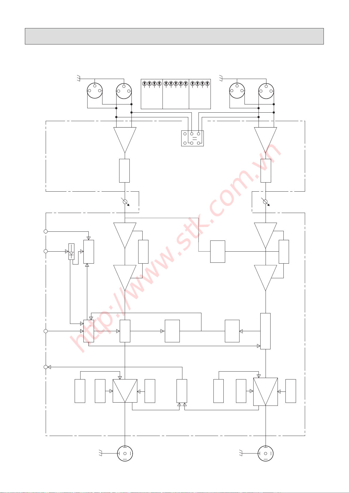
Ⅰ Introduction
l
제품 소개
AMPLIFIER BLOCK
6. Block Diagram
l
회로의 구성도
13
2
13
2
13
2
13
2
HI PASS
FILTER
BAL
AMP
HI PASS
FILTER
BAL
AMP
CH 2 INPUT
CH 1 INPUT
BAL INPUT CH 1
OUTPUT
THROUGH
OUTPUT
CLIP
-10
-30
SIG
POWER
PRT
PRT
PARALLEL
BRIDGE
CLIP
-10
-30
SIG
PRE
GAIN
NEGATIVE
STEP
MUTE
CONTROL
CLIP
LIMIT
CURRENT
SPLITTER
THERMAL &
BIAS
SENSING
MONO
BRIDGE
ROUTING
THERMAL &
BIAS
SENSING
CURENT
SPLITTER
FAN
CONTRL
CLIP
LIMIT CH 2
OUPUT
OUPUT
NEGATIVE
STEP
OUPUT
POSITIVE
STEP
CURRENT
LIMITER
CURRENT
LIMITER
DC FAULT
DETECTOR
POSITIVE
STEP
PRE
GAIN
ATT
LOOP GAIN
FEEDBACK
LOOP GAIN
FEEDBACK
HI FREQ RECTIFIERS
ST-BY +15V SWICH MUTE DC-OFF
PARALLEL
MODE
ON/OFF
19
FOR VS-34/VS-40 ONLY
http://www.stk.com.vn

7. Specications
l
제품 규격
20
Model VS-34 VS-40
Output Power Per Channel / 최대 출력
at 1㎑ / THD ≤1.0% EIA
2 Ω
4 Ω
8 Ω
1700W (Short term)*3
1400W/*3
850W/*3
2000W(Short Term)
1800W/*3
1050W/*3
Rated Output Power Per Channel Drive / 정격 출력
at 20㎐~20㎑ / THD ≤0.5%
2 Ω
4 Ω
8 Ω
Bridged Mono
1600W/*3
1300W/*3
830W/*3
1×3400W@4 Ω/*3(Short term)
1800W
1750W/*3
1040W/*3
1×4000W@4 Ω/*3 (Short term)
Total Harmonic Distortion / 왜율
f=1 ㎑, at rated power <0.05% <0.05%
IMD-SMPTE / 혼합변조왜율
4Ω, Stereo, 1/2 power
f=60㎐+7㎑, 4:1
<0.1% <0.1%
Frequency Response / 주파수 응답
-1㏈, 1Watt output 20㎐ - 25㎑ 20㎐ - 25㎑
Power Bandwidth -1.5㏈,Stereo / 전력 대역폭 20㎐ - 20㎑ 20㎐ - 20㎑
Signal To Noise Ratio / 신호대 잡음비
A-weighted. RMS ≥102 ㏈ ≥102 ㏈
Residual Noise / 잔류 잡음
LPF level minimum ≥-67㏈ ≥-67㏈
Damping Factor 8Ω, 50 ㎐ / 댐핑 팩터 ≥400 ≥400
Slew Rate 8Ω, 1㎑, Rated Output / 슬루율 84.9 V/μsec 97 V/μsec
Channel Separation 8Ω, 1㎑, Rated Output
/ 채널 분리도 ≥64 ㏈ ≥64 ㏈
4 Ω Input Sensitivity (VR Max.) / 4 Ω 입력 감도 +0 or +4.0 or +7.0 dBu by Select Switch +0 or +4.0 or +7.0 dBu by Select Switch
8 Ω Input Sensitivity (VR Max.) / 8 Ω 입력 감도 Up to +2.1 dBu from 4 ohm/Stereo Input Up to +2.1 dBu from 4 ohm/Stereo Input
Input Impedance / 입력 임피던스 ≥12 k ohm ≥12 k ohm
Indicators *1 / 표시등 1, 2, 3, 4, 5, 6 1, 2, 3, 4, 5, 6
Cooling / 냉각방식 Variable Fan Variable Fan
Protection Circuit *2 / 보호회로 *2 1, 2, 3, 4, 5, 6, 7 1, 2, 3, 4, 5, 6, 7
Front Panel Controls / 전면부 조절 Level, Ach, Bch Level, Ach, Bch
Rear Panel Controls / 후면부 조절
Parallel, Mono/Bridge Mode, Clip
Limiter, Filter ON/OFF, Sensitivity
Selector
Parallel or Mono/Bridge Mode, Clip
Limiter, Filter ON/OFF, Sensitivity
Selector
DC Offset Voltage / 출력 중점 직류전압 ≥DC 10㎷ ≥DC 10㎷
Dimension (W×D×H) mm / 외형 치수 483×88×495mm 483×88×495mm
Weight Net / 제품 무게
㎏ (lbs) Shipping / 포장박스 포함
14.98 (32.84)
16.66 (36.59)
16.08 (35.27)
17.58 (38.58)
Power Consumption / 소비전력 2300 Watts 2700 Watts
AC Fuse / 입력 퓨즈 120V: 50A, 220V/240V: 30A 120V: 60A, 220V/240V: 30A
Connector / 사용커넥터
All input balanced type.
/모든 입력은 밸런스드 타입입니다.
XLR input,
XLR Through Output
Speakon Output
XLR input,
XLR Through Output
Speakon Output
http://www.stk.com.vn
This manual suits for next models
2
Other STK Professional Audio Amplifier manuals

STK Professional Audio
STK Professional Audio V-6 User manual

STK Professional Audio
STK Professional Audio VS-34 Power Plus User manual

STK Professional Audio
STK Professional Audio VS-15 User manual

STK Professional Audio
STK Professional Audio V-16 Plus 4 User manual

STK Professional Audio
STK Professional Audio V-3.5M User manual

STK Professional Audio
STK Professional Audio V-9 User manual

STK Professional Audio
STK Professional Audio VP-150 User manual

STK Professional Audio
STK Professional Audio V-2 User manual

STK Professional Audio
STK Professional Audio V-9T User manual

STK Professional Audio
STK Professional Audio VS-2004 User manual


