monolith M8250X User manual

M8250x 8x200 Watts Per Channel Class-D Multi-
Channel Home Theater Power Amplifier (42564)
M8125x 8x100 Watts Per Channel Class-D Multi-
Channel Home Theater Power Amplifier (42565)
P/Ns 42564, 42565
User's Manual

2
CONTENTS
SAFETY WARNINGS AND GUIDELINES................................................................................................................................... 3
INTRODUCTION..........................................................................................................................................................................................4
FEATURES........................................................................................................................................................................................................4
CUSTOMER SERVICE ..............................................................................................................................................................................5
PACKAGE CONTENTS............................................................................................................................................................................5
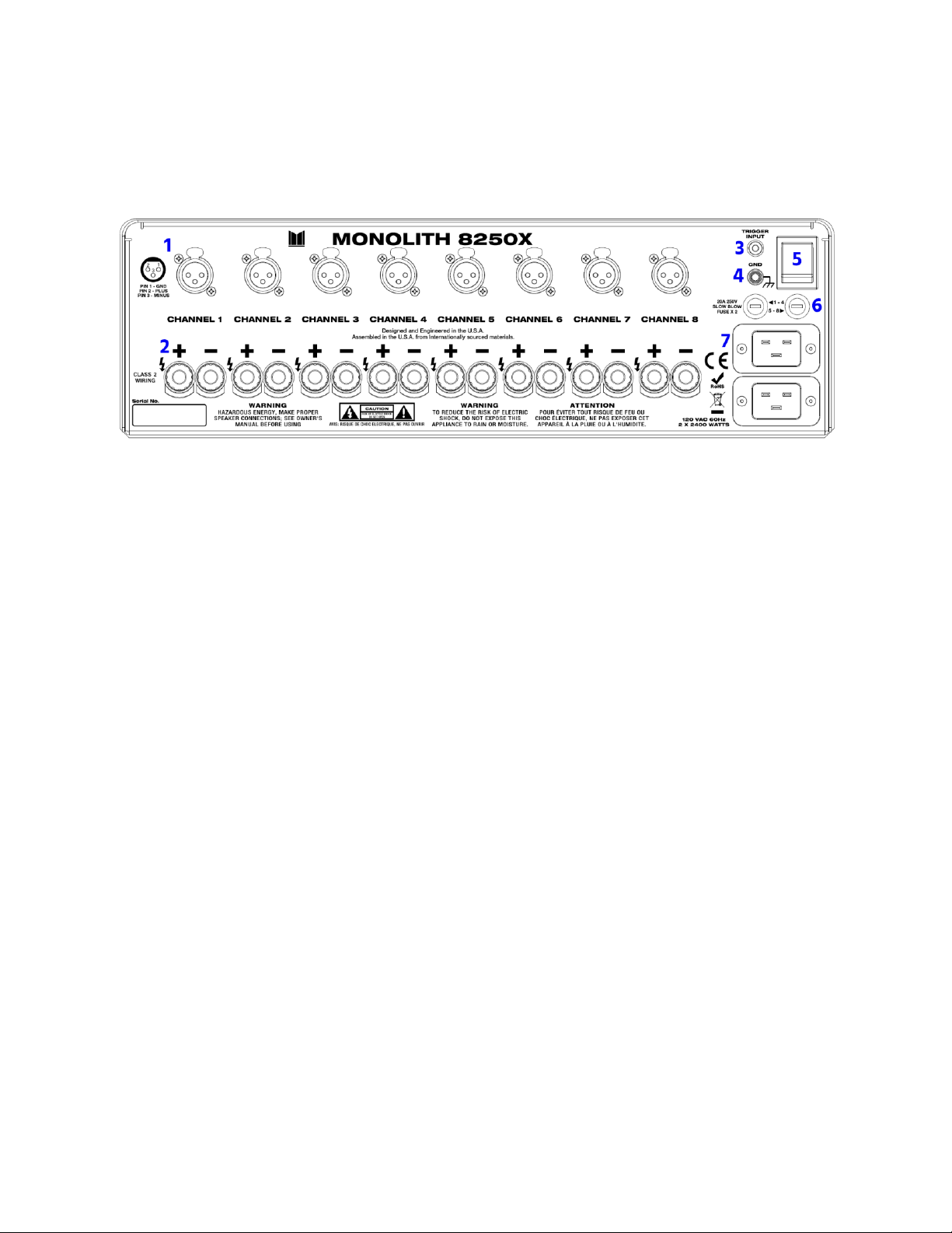
PRODUCT OVERVIEW ...........................................................................................................................................................................6
42564............................................................................................................................................................................................................6
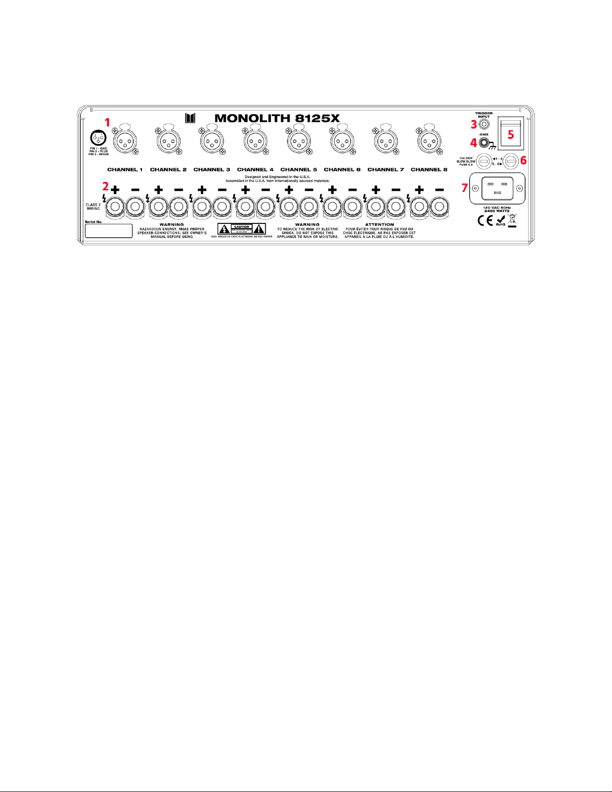
42565............................................................................................................................................................................................................ 7
CABLE PREPARATION............................................................................................................................................................................8
Speaker Wires .......................................................................................................................................................................................8
XLR Cables................................................................................................................................................................................................8
Trigger Cable..........................................................................................................................................................................................9
REMOTE POWER ON..............................................................................................................................................................................9
INSTALLATION ............................................................................................................................................................................................9
FUSES ................................................................................................................................................................................................................11
PROTECTION CIRCUITRY.................................................................................................................................................................... 11
TROUBLESHOOTING..............................................................................................................................................................................11
TECHNICAL SUPPORT..........................................................................................................................................................................12
SPECIFICATIONS...................................................................................................................................................................................... 13
REGULATORY COMPLIANCE .........................................................................................................................................................16
Notice for FCC.....................................................................................................................................................................................16
Notice for ISED Canada............................................................................................................................................................... 17

3
SAFETY WARNINGS AND GUIDELINES
•This device is intended for indoor use only.
•Do not expose this device to water or moisture of any kind. Do not place drinks or
other containers with moisture on or near the device. If moisture does get in or on
the device, immediately unplug it from the power outlet and allow it to fully dry
before reapplying power.
•Do not touch the device, the power cord, or any other connected cables with wet
hands.
•Do not expose this device to excessively high temperatures. Do not place it in, on,
or near heat sources, such as a fireplace, stove, radiator, etc. Do not leave it in direct
sunlight.
•This device ventilates excessive heat through the slots and openings in the case. Do
not block or cover these openings. Ensure that the device is in an open area where
it can get sufficient airflow to keep from overheating.
•Do not place or install this device in an area where it can be exposed to excessive
amounts of dust, humidity, oil, smoke, or combustible vapors.
•Prior to operation, check the unit and power cord for physical damage. Do not use if
physical damage has occurred.
•Take care to prevent damage to the power cord. Do not allow it to become
crimped, pinched, walked on, or become tangled with other cords. Ensure that the
power cord does not present a tripping hazard.
•Before plugging the unit into a power outlet, ensure that the outlet provides the
same type and level of power required by the device.
•This device uses a grounded power cord and requires a ground connection for safe
operation. Ensure that the power source has a proper ground connection. Do not
modify the plug or use a "cheater" plug to bypass the ground connection.
•Ensure that power is turned off and disconnected before making any electrical
connections.

4
•Do not plug this device into the switched output of a preamplifier or other audio
component. This amplifier requires higher current levels than these devices are
designed to handle.
•Unplug this device from the power source when not in use.
•Never unplug the unit by pulling on the power cord. Always grasp the connector
head or adapter body.
•Clean using a soft, dry cloth only. Do not use chemical cleaners, solvents, or
detergents. For stubborn deposits, moisten the cloth with warm water.
•This device has no user serviceable parts. Do not attempt to open, service, or
modify this device.
INTRODUCTION
This power amplifier features eight channels, each of which is capable of outputting more
than 200 watts (42564) or 100 watts (42565) of power into 8 ohm loads. A trigger input
allows for remote power on when a source device is powered on. Each channel is
protected with Hypex® protection circuits for superior fault protection.
FEATURES
•20Hz ~ 20kHz ±0.5dB frequency response
•Eight balanced 3-pin XLR inputs
•200 watts per channel into 8 ohms (42564 only)
•100 watts per channel into 8 ohms (42565 only)
•Rated for 4 ~ 16 ohm loads
•Hypex® protection circuits

5
CUSTOMER SERVICE
The Monoprice™ Customer Service department is dedicated to ensuring that your ordering,
purchasing, and delivery experience is second to none. If you have any problem with your
order, please give us an opportunity to make it right. You can contact a Monoprice
Customer Service representative through the Live Chat link on our website
www.monoprice.com or via email at support@monoprice.com. Check the website for
support times and links.
PACKAGE CONTENTS
Please take an inventory of the package contents to ensure you have all the items listed
below. If anything is missing or damaged, please contact Monoprice Customer Service for a
replacement.
1x M8250X or M8125X 8-Channel Power Amplifier
2x High-Current AC Power Cords (42564 only)
1x High-Current AC Power Cord (42565 only)
1x Trigger Cable

6
PRODUCT OVERVIEW
42564
1. INPUTS: Eight balanced XLR line inputs for connecting to the preamplifier outputs
on a dedicated preamplifier or AV receiver.
2. OUTPUTS: Eight pairs of 5-way binding posts for connecting the speakers.
3. TRIGGER INPUT: 3.5mm TS jack for connection to the trigger output of a source
device. The presence of voltage on this input will cause the amplifier to power on.
The amplifier will automatically power down into standby mode after the trigger
signal has been removed.
4. GND: Chassis ground. While a grounding wire is rarely needed, occasionally there is
a hum issue when components are interconnected. This can be remedied by tying
their chassis grounds together.
5. MASTER POWER: The Master Power switch is used to apply or remove power to the
amplifier. By contrast, the Power Switch on the front panel is used to switch the
amplifier between standby mode and full power on.
6. FUSES: Two fuse holders, each of which contains a 20A slow-blow ceramic 5x20
fuse. The fuse on the left protects channels 1-4, while the one on the right protects
channels 5-8.
7. AC INPUTS: Two IEC 60320 C20 panel connectors for connecting the included high-
current AC power cords.

7
42565
1. INPUTS: Eight balanced XLR line inputs for connecting to the preamplifier outputs
on a dedicated preamplifier or AV receiver.
2. OUTPUTS: Eight pairs of 5-way binding posts for connecting the speakers.
3. TRIGGER INPUT: 3.5mm TS jack for connection to the trigger output of a source
device. The presence of voltage on this input will cause the amplifier to power on.
The amplifier will automatically power down into standby mode after the trigger
signal has been removed.
4. GND: Chassis ground. While a grounding wire is rarely needed, occasionally there is
a hum issue when components are interconnected. This can be remedied by tying
their chassis grounds together.
5. MASTER POWER: The Master Power switch is used to apply or remove power to the
amplifier. By contrast, the Power Switch on the front panel is used to switch the
amplifier between standby mode and full power on.
6. FUSES: Two fuse holders, each of which contains a 10A slow-blow ceramic 5x20
fuse. The fuse on the left protects channels 1-4, while the one on the right protects
channels 5-8.
7. AC INPUTS: IEC 60320 C20 panel connector for connecting the included high-current
AC power cord.

8
CABLE PREPARATION
You will need several cables for this installation. None of the cables or connectors
mentioned in this section are included with the system.
Important Safety Note! If you plan on running any of these cables through the walls,
through a connecting floor, or inside an air duct, they should be rated for In-Wall, Riser
(between floors), or Plenum (air duct) use in commercial installations. For residential
installations, an In-Wall rating is sufficient for all circumstances. Using unrated or
improperly rated cables could accelerate the spread of any fire and could nullify insurance
claims.
Speaker Wires
You will need eight speaker wires to connect each speaker to the amplifier. The size (AWG)
of wire you choose depends on the distance from the amplifier to the speakers, the
speaker impedance, and the physical limits of the terminals at each end.
Other than saving a few pennies of cost or grams of weight per foot, there is no reason to
use anything other than the thickest wire possible. This amplifier uses 5-way binding post
connectors, which can accept bare wire, spade lugs, banana plugs, and pin plugs. For
anything other than extremely short speaker wire runs, you should use at least 14AWG
wire, but preferably 12AWG or 10AWG, depending on which gauges your speakers can
accept.
Whichever speaker wire you get, make sure that it has marks to identify one conductor
from another. Most speaker wire uses a colored stripe to identify one of the conductors.
The identified conductor is usually used for the positive (+/red) connection and the other
for the negative (-/black) side.
XLR Cables
You will need eight XLR cables to connect the preamp outputs on your preamplifier to the
inputs on this amplifier. If your preamp has RCA outputs, instead of XLR, you can use an
RCA to XLR cable to make the connections, such as PID 4777.

9
Trigger Cable
This amplifier features a low voltage trigger input, which can switch the amplifier from
standby mode into full power on mode whenever the trigger signal is detected. The trigger
signal consists of a low-current, low-voltage signal (between 3.3 and 24.0 VDC) applied to
the input, which is carried between components with a cable that terminates in a 3.5mm
TS plug.
REMOTE POWER ON
This amplifier features a trigger input, which is used to switch the amplifier between
standby mode and full power on mode. The input is a 3.5mm TS jack that accepts a voltage
level from 3.3 to 24.0 VDC. Some source devices feature a trigger output, which can be
used to trigger the amp.
If your source device does not contain a trigger output, but does have a switched AC
outlet, you can obtain a trigger adapter, which consists of an AC adapter with a 3.5mm TS
plug on the end of the cord. This adapter can then provide the necessary trigger signal
whenever the component it is plugged into is turned on.
To use the amplifier with remote power on, the Master Power switch on the rear panel
should be in the ON position and the Power Switch on the front panel also in the ON
position.
To override the remote power on feature or to use the amp without it, simply use the
Power Switch on the front panel to turn the amp on and off (standby).
INSTALLATION
Perform the following steps to install this amplifier.
1. Power off and unplug all equipment that will be connected to this amplifier.
2. Prepare eight lengths of speaker wire (not included) to connect each of the eight
output channels to its respective speaker.

10
3. Using a two-conductor speaker wire, connect one end to the input terminals on the
speaker, then connect the other end to the Output terminals on the amplifier. Take
care to maintain polarity with positive to positive and negative to negative.
4. Repeat step 3 for each of the other seven speakers.
5. Using an XLR cable (not included), plug one end into the Input on the amplifier,
then plug the other end into the appropriate preamplifier output.
6. Repeat step 5 for each of the other seven channels.
7. (Optional) Using the included Trigger Cable, plug one end into the Trigger Input on
the amplifier, then plug the other end into the trigger output on your source device.
8. Ensure that the Master Power switch is in the OFF position and that the Power
Switch is in the Standby position.
9. Using the included AC Power Cable, plug the C19 connector on the cable into the
C20 panel connector on the amplifier, then plug the other end into a nearby AC
power outlet. Repeat with the second AC input for 42564. Note that each input
should be plugged into a different AC circuit.
Warning! Do not plug the amplifier into a switched outlet on a preamplifier or other
audio component. The amplifier should be plugged directly into an AC wall outlet.
10. Ensure that the volume on the preamplifier is set to the minimum level.
11. Power on all equipment connected to the amplifier, then flip the Master Power
switch on the rear panel to the ON position. Press the Power Switch on the front
panel. The LED will illuminate dimly until the circuitry is properly warmed up. Once
the LED illuminates brightly, the amplifier has finished the start-up process and is
ready for operation.
Note: It is recommended to always turn the amplifier on last and to turn it off first
whenever powering your audio system on or off. This ensures that any pops or
transient spikes, which could cause damage to the delicate speaker coils, are not
sent to your speakers.
Congratulations, your amplifier is connected and ready for use!

11
FUSES
The system uses two fuses to protect the circuitry from excessive current. P/N 42564 uses
two 20A slow-blow/time lag ceramic 5x20 fuses, while P/N 42565 uses two 10A slow-
blow/time lag ceramic 5x20 fuses.
PROTECTION CIRCUITRY
This amplifier uses protection circuitry by Hypex® to protect it from common faults. The
protection circuits work as follows:
•Over Temperature Protection: Whenever a module overheats, it will automatically
mute. When the temperature returns to normal, it will un-mute and resume audio
amplification.
•DC Error Protection: When a DC error occurs, the SMPS turns off and the front panel
LED will blink a number of times to indicate which module has the fault (1 blink =
module 1, 2 blinks = module 2, 3 blinks = module 3, and 4 blinks = module 4). To reset
the amplifier from this fault, unplug it from the AC power source, wait 30 seconds,
then plug it back in again.
•Power On: All amplifier modules are muted during power on. The modules will
sequentially power on, starting with module 1 and ending with module 4.
TROUBLESHOOTING
Q1. The amplifier will not power on.
A1. Verify that the Master Power switch on the rear panel is in the ON position. Check to
ensure that the AC power cord is fully plugged in at each end. Verify that the AC
power outlet is live by plugging in another device, such as a lamp.

12
Q2. Audio from some channels, but not others.
A2. Try swapping the speaker from a good channel to the output of the bad channel to
see if the problem is with the input or output. Check that the XLR input cable is firmly
seated on the connector at each end. Try swapping out the input XLR cable with a
known good cable. Check the speaker wire connections at each end. Try swapping out
the speaker wire with a known good one.
Q3: Audio plays, then cuts off.
A3: Check the speaker wire connections for stray wire strands, which could cause a short
circuit.
TECHNICAL SUPPORT
Monoprice™ is pleased to provide free, live, online technical support to assist you with any
questions you may have about installation, setup, troubleshooting, or product
recommendations. If you ever need assistance with your new product, please come online
to talk to one of our friendly and knowledgeable Tech Support Associates. Technical
support is available through the online chat button on our website www.monoprice.com
support times and links.
To download the latest drivers, firmware, manuals, etc., go to www.monoprice.com and
type the P/N into the search bar. If available, support files are linked at the bottom of the
product page.

13
SPECIFICATIONS
P/N
42564
Model
M8250X
Inputs
8x balanced XLR
Input Impedance
47kΩ
Gain
25.7dB
Frequency Response at Rated Output
20Hz ~ 20kHz ±0.5dB
Signal-to-Noise Ratio (A-Weighted)
Greater than 115dB below rated FTS Full
Bandwidth Power
Measurements into 8-Ohm Loads
FTC Full Bandwidth (20Hz ~ 20kHz) Output
Power
200 watts (all channels driven)
Input Sensitivity for Full Rated Power
2.07 volts
Total Harmonic Distortion + Noise (THD+N)
@ 20Hz ~ 20kHz
Less than 0.05% (20Hz ~ 5kHz)
Less than 0.5% (5kHz ~ 20kHz)
Total Harmonic Distortion + Noise (THD+N)
@ 1kHz
< 0.01% at Rated Power
Measurements into 4-Ohm Loads
FTC Full Bandwidth (20Hz ~ 20kHz) Output
Power
400 watts (4 channels driven)
Input Sensitivity for Full Rated Power
2.07 volts
Total Harmonic Distortion + Noise (THD+N)
@ 20Hz ~ 20kHz
Less than 0.1% (20Hz ~ 5kHz)
Less than 0.5% (5kHz ~ 20kHz)

14
Total Harmonic Distortion + Noise (THD+N)
@ 1kHz
< 0.025% at Rated Power
Hypex® Ratings
8-ohm Load, 1kHz, 1% THD
350 watts
4-ohm Load, 1kHz, 1% THD
500 watts
2-ohm Load, 1kHz, 1% THD
450 watts (current limited)
Load Impedance
Rated for 4 ~ 16 ohm loads
1 Watt Power Bandwidth
+0, -3dB from 10Hz ~ 48kHz
Damping Factor
Greater than 400 from 20Hz ~ 400Hz
Crosstalk
Better than -70dB, 200Hz ~ 20kHz
DC Output Offset
Less than ±20mV
Remote Trigger Voltage
3.3 ~ 24.0 VDC, 5mA
Input Power
120 VAC, 60Hz
Dimensions (with binding posts) (HxWxD)
5.25" (3RU) x 17.1" x 14.5"
Weight
35.5 lbs. (16.1 kg)
P/N
42565
Model
M8125X
Inputs
8x balanced XLR
Input Impedance
47kΩ
Gain
25.7dB
Frequency Response at Rated Output
20Hz ~ 20kHz ±0.5dB

15
Signal-to-Noise Ratio (A-Weighted)
Greater than 115dB below rated FTS Full
Bandwidth Power
Measurements into 8-Ohm Loads
FTC Full Bandwidth (20Hz ~ 20kHz) Output
Power
100 watts (all channels driven)
Input Sensitivity for Full Rated Power
1.465 volts
Total Harmonic Distortion + Noise (THD+N)
@ 20Hz ~ 20kHz
Less than 0.05% (20Hz ~ 5kHz)
Less than 0.5% (5kHz ~ 20kHz)
Total Harmonic Distortion + Noise (THD+N)
@ 1kHz
< 0.01% at Rated Power
Measurements into 4-Ohm Loads
FTC Full Bandwidth (20Hz ~ 20kHz) Output
Power
175 watts (4 channels driven)
Input Sensitivity for Full Rated Power
1.37 volts
Total Harmonic Distortion + Noise (THD+N)
@ 20Hz ~ 20kHz
Less than 0.1% (20Hz ~ 5kHz)
Less than 0.5% (5kHz ~ 20kHz)
Total Harmonic Distortion + Noise (THD+N)
@ 1kHz
< 0.025% at Rated Power
Hypex® Ratings
8-ohm Load, 1kHz, 1% THD
150 watts
4-ohm Load, 1kHz, 1% THD
250 watts
2-ohm Load, 1kHz, 1% THD
180 watts (current limited)
Load Impedance
Rated for 4 ~ 16 ohm loads

16
1 Watt Power Bandwidth
+0, -3dB from 10Hz ~ 50kHz
Damping Factor
Greater than 400 from 20Hz ~ 400Hz
Crosstalk
Better than -70dB, 200Hz ~ 20kHz
DC Output Offset
Less than ±20mV
Remote Trigger Voltage
3.3 ~ 24.0 VDC, 5mA
Input Power
120 VAC, 60Hz
Dimensions (with binding posts) (HxWxD)
5.25" (3RU) x 17.1" x 12.5"
Weight
28.2 lbs. (12.8 kg)
REGULATORY COMPLIANCE
Notice for FCC
This device complies with Part 15 of the FCC rules. Operation is subject to the following
two conditions: (1) this device may not cause harmful interference, and (2) this device must
accept any interference received, including interference that may cause undesired
operation.
Modifying the equipment without Monoprice's authorization may result in the equipment
no longer complying with FCC requirements for Class B digital devices. In that event, your
right to use the equipment may be limited by FCC regulations, and you may be required to
correct any interference to radio or television communications at your own expense.
This equipment has been tested and found to comply with the limits for a Class B digital
device, pursuant to Part 15 of the FCC Rules. These limits are designed to provide
reasonable protection against harmful interference in a residential installation. This
equipment generates, uses and can radiate radio frequency energy and, if not installed and
used in accordance with the instructions, may cause harmful interference to radio
communications. However, there is no guarantee that interference will not occur in a

17
particular installation. If this equipment does cause harmful interference to radio or
television reception, which can be determined by turning the equipment off and on, the
user is encouraged to try to correct the interference by one or more of the following
measures:
•Reorient or relocate the receiving antenna.
•Increase the separation between the equipment and receiver.
•Connect the equipment into an outlet on a circuit different from that to which the
receiver is connected.
•Consult the dealer or an experienced radio/TV technician for help.
Notice for ISED Canada
This Class B digital apparatus complies with Canadian ICES-003.
Cet appareil numérique de la classe B est conforme à la norme NMB-003 du Canada.
Monoprice™, Monolith™, the Monolith logo, and all Monoprice logos are trademarks of
Monoprice Inc.
Hypex® is a trademark of Hypex Electronics B.V.
This manual suits for next models
3
Table of contents