9
RAM/EE – The first screen under this option asks, “Clear all test data – Y/N?” A “Y(es)” response
will permanently erase all accumulated test data from memory. The next two windows prompt a
similar decision for whether to restore defaults to Group/Location names and test setups. These
decisions should not be taken lightly as deletions are irreversible.
S/N – Displays software revision number and instrument serial number. These cannot be modified.
RETURN – Returns to SETUP Menu
SETUP for Manual Test Menu:
Figure 4. Setup – Manual Screen: In the Setup screen (Figure 2), press “MANUAL” key.
This screen displays a list
of five user selectable
manual test options.
Three of them; M.Setup
1, M.Setup 2 and M.
Setup 3 may be modified.
The “Factory” option uses
“standard” settings and
the “Test” option has
settings used during factory testing of each unit. These two may not be changed.
The parameters of any of the manual tests may be viewed or those of the first three edited to meet user
requirements by highlighting the test and pressing the DISPLAY key. To change these parameters, see
Programming Features for Manual Tests.
A symbol “D>” indicates which one is selected as the default test. To change the default, scroll to
highlight one of the options using the NEXT key and press the DEFAULT key. The selected test will
remain the default test until re-selected. Previously stored test results are not affected by a new default
setting but all subsequent tests will be made with the new default until changed by this method.
SETUP for Auto Sequence Menu:
The Auto Sequence Setup screen works the same. It displays a list of five user selectable manual test
options. Three of them; A.Setup 1, A.Setup 2 and A. Setup 3 may be modified. The “Factory” option
uses “standard” settings and the “Test” option has settings used during factory testing of each unit.
These two may not be changed.
Figure 5. Setup – Auto screen: In the Setup screen (Figure 2), press the “AUTO” key.
The parameters of any of the manual tests
may be viewed or those of the first three
edited to meet user requirements by
highlighting the test and pressing the
DISPLAY key. See Programming
Features for Auto Sequence Tests later in
this manual.
A symbol “D>” indicates which one is
selected as the default test. To change the
default, scroll to highlight one of the options using the NEXT key and press the DEFAULT key. The
selected test will remain the default test until re-selected. Previously stored test results are not affected
by a new default setting but all subsequent tests will be made with the new default until changed by this
method.
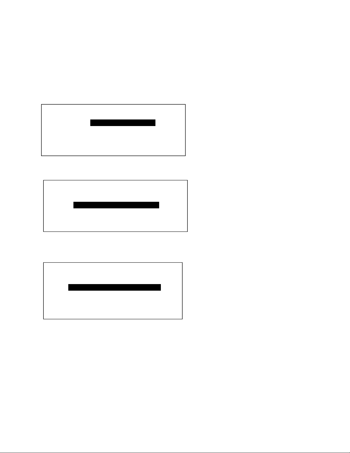
SETUP A.TEST
D> A.Setup 1
A.Setup 2
A.Setup 3
Factory
Test
NEXT DISPLAY DEFAULT SETUP MAIN
SETUP M.TEST
D> M.Setup 1
M.Setup 2
M.Setup 3
Factory
Test
NEXT DISPLAY DEFAULT SETUP MAIN
The first three
setups can be
modified.
M.Setup 1 is
current
selected as
default setup
for use.