STEP 4:
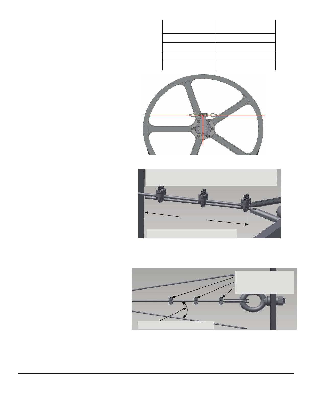
Attach the supplied 1/2"-13 eye bolts to nearby suitable
supports using supplied lockwashers and nuts. Each
eye bolt should be as near to straight line opposite
each other as possible (see Figure 4). Effectively cre-
ating an imaginary line through the junction of the dou-
ble cable link bar center point with the AirBrake® arm.
While 180° is the optimum cable placement, it is allow-
able for the cables to form as small an angle as 90° on
the plane of the AirBrake® arm. Secure the free ends
of the restraining cables to the eyebolts by first insert-
ing one of the supplied thimbles through each eye bolt.
Pass each cable around its associated thimble and se-
cure with three wire rope clips on each cable. See Fig-
ure 5 for proper rope clip installation. Ensure that the
attachment of the cable to the support will not make the
cable more than plus or minus 10° out of level as illus-
trated in Figure 6. Remove as much slack as practical
from each cable. However, cables should NOT be
taught. Apply Loctite 262 (or equivalent) to the threads
of the rope clips and tighten the clips.
Table 1. Torque values for installation bolts.
STEP 5.
After installation of the restraining cables, check by hand
for free rotation of the fan in the normal direction. Then,
again by hand, attempt to rotate the fan in the back-
wards direction and ensure the AirBrake® is working
properly. In the normal rotation direction of the fan, it is
likely that both cables will be very slightly slack. In the
backwards direction one cable should be taught. En-
sure that neither cable may be in contact with any edge
or surface (moving or stationary) which might lead to
fraying and failure of the cable.
STEP 6.
Install all required guards and confirm there is sufficient
clearance for the AirBrake® .
STEP 7.
After all of the necessary guards have been installed,
run the fan at full speed, ensure that the cables are
not overly tight and are positioned properly with all
things working correctly.
No more than ± 10° out of level
Use the wire rope clips
and apply Loctite to the
threads to secure cable.
Moore Fans
TMC 878 REV H (Jun 2018)
Live End
Figure 5. Proper installation of wire rope clips.
Figure 6. Restraining cable angle tolerance.
Dead End
Turnback
Position saddle side of the clip on the live end and the
u-bolt side of clip on the dead end
Allow 4.75 in (120.65mm) of turnback
Live End
QD Bushing Size Torque
E 60 ft-lbs (8.3 kg-m)
F 75 ft-lbs (10.4 kg-m)
J 135 ft-lbs (18.7 kg-m)
SF 50 ft-lbs (6.9 kg-m)
800 S. Missouri Ave
Marceline, MO 64658
Phone: 660-376-3575
Fax: 660-376-2909
www.moorefans.com
Figure 4.


