manuals.online logo
Brands
  1. Home
  2. •
  3. Brands
  4. •
  5. MOPA-TOP
  6. •
  7. Boiler
  8. •
  9. MOPA-TOP ELECTRA Comfort 24 User manual

MOPA-TOP ELECTRA Comfort 24 User manual

ec
Wallhung eltric boiler
ec
Wallhung eltric boiler
Instruction manual Instruction manual
ELECTRA COMFORT 2
Contents Transport and warehousing
General information Claims
Description and use
Advantages of boiler Way of liquidation
Important directions and advises
Enclosures
Boiler attendance
3. Installation
Ending of operation
Maintenance
Full delivery
7. . . . . . . . 31
1. 8. . . . . . . . . . . . . . . . . . . . . . . 31
1.1 . . . . . . . . . . . . . . . . . .. . . . . .3
1.2 . . . . . . . . . . . . . . . . . . . . . . . . . 3 9. . . . . . . . . . . . . . . 31
1.3 . . . . . . . . . . . 3
1.3.1 Mounting .. . . . . . . . . . . . . . . . . . . . . . . . . . . 4 10. . . . . . . . . . . . . . . . . . . . . . . 32
1.3.2 Putting into operation. . . . . . . . . . . . . . . . . .4
1.3.3 Boiler operation.. . . . . . . . . . . . . . . . . . . . .. . . 4
1.3.4 Safety. . . . . . . . . . . . . . . . . . . . . . . . . . . . . . . 4 10.1 Installation of room thermostat. . . . .. .32
1.4 Main dimensions. . . . . . . . . . . . . . . . . . . . . 5 10.2 Face of control unit. . . . . . . . . . . . . . .33
1.5 Technical data. . . . . . . . . . . . . . . . . .. . . . . .6
1.6 Main parts . . . . . . . . . . . . . . . . . . .. . . . . . .8
1.7 Description of functions. . . .. . . . . . . . . . . . 9
1.7.1 Technical description . . . . . . . . . . .. . . . . . . .9
1.7.2 Principle of boiler operation. . .. . .. . . . . . . . . 9
1.7.3 Control unit and control panel . .. . . . . . . . . . .9
1.7.4 Protection function of the boiler . . . . . . . . . . .10
1.7.5 Safety function of the boiler. . . . . . . . . . . . .10
1.8 Circuit diagram. . . . . . . .. . . . . . . . . . . . . . 11
2.
2.1 Control panel. . . . . . . . . . . . . . . . . . . . . .16
2.2 Switch on/off . . . . .. . . . . . . . . .. . . . . . . 18
2.3 Operation modes. . . . . . .. . . . . . . . . . . . . 18
Meaning of abbreviations and used symbols
2.3.1 Operation mode (heating water). . . . . . . . .18
2.3.2 Operation service utility water (sanitary water)..20
OV -
2.4 Setting of boiler parameters heating water
. . .. . . . . . . . 21
TUV -
2.5 Breakdowns. service utility water (sanitary water)
. . . . . . . . . . . . . . . . . . . . . . . 27
ZOV - storage water tank
TMV - three ways valve
3.1 Norms and regulation. . . . . . . . . . . . . . . .28
3.2 Placement of the boiler. . . . . . . . . . . . . . .28
3.3 Instalace na stěnu. . . . . . . . . . . . . . . . . . . 28
3.4 Wall hung installation of the boiler. . . . . 28 Notice pay attention
3.4.1 Electric installation of the boiler. . . . . . . . . . 28
3.4.2 Connection of the boiler to electric supply network. .
. . . .. . . . . . . . . . . . . . . . . . . . . . . . . .29
3.4.3 Installation of the room thermostat . . . . . . . . 29
3.4.4 Installation of three-ways valve for water heating
in storage water tank. . . . . . . . . . . . . . . . . 29
3.5 Heating system. . . . . . . . . . . . .. . . . . . . .29
3.6 Expansion vessel. . . . . . . . . . . . . . . . . . . . . .29
3.7 Marking of working scale. . . . . . . . . . . . . . 30
3.8 Circle pump. . . . . . . . . . . . . . . . . .. . . . . . . 30
.
4. . . . . . . . . . . .. . . . 31
5. . . . . . . . . . . . . . .. . . . . . . . . . . . . 31
6. . . . . . . . . . . 31
boiler could be regulated by the room thermostat and it
Dear customer, also able to heat sanitary water in an independent storage
You have bought a modern product the direct heated water tank connected through with 3-ways motoric valve.
electric boiler ELECTRA Comfort from the company
MORA-TOP, Czech Republic. We believe that our product 1.2 Advantages of boiler
will serve you good and for long time. It is necessary for
you to study whole instruction manual and hold all the small dimensions, modern design
†
principles. The declaration of conformity was issued by high efficiency 99 %
†
the producer according to directives 2004/108/EC, silent operation
2006/95/EC, †
information on the display
†
mode relay independent to the control unit cost
†
saving regarding replacement
Boilers MORA-TOP are electric, using water for heating.
†step less regulation of boiler output with continuous
†
It is electric wall-hung appliance determined for switching on/off heating elements economic
heating of family houses or flaks with heat loss to 22,5 operation
kW. rotation of heating elements ensuring elongation of
†
The boiler could be used for heating of service utility
†lifetime
water (sanitary water) through storage water tank. possibility of using the boiler for under floor heating
†
The boiler could be remote controlled by GSM.
†system
breakdowns diagnostic system with display indication
†
information about heating system pressure thermo
†
manometer
operation mode Stand-by ensuring termination of
†
SIMPLE CONTROL - you new boiler is in operation boiler operation with all protective functions:
automatically. After boiler professional putting into †protective functions:
operation is not necessary any additional setting. The †antifreeze
boiler will adapt to conditions of your heating system †deblocking
†against overheating
DIMENSIONS - your new boiler is really small regarding †against pressure lost
its dimensions. You can place it anywhere where is pump running out regulated by time or temperature
†
impossible to place another type of boilers. possibility of remote control with GSM
†
REMINDER! possibility of equitermic operation
†
Your new boiler is not stay alone to be useful for your possibility of connection with a storage water tank
†
comfort, use good outside insulation of your flat or your possibility of a room thermostat connection
†
house, use the room thermostat for economical automatic deaerating
consumption of electric energy. †
breakdowns statement memory
†
function back to factory setting.
†
MORA-TOP s.r.o
1.3
1. General information
1.1 Description and use Regarding installation, putting the boiler into operation
and maintenance it is necessary to observe instructions
The wall hung electric boiler ELECTRA Comfort is according to concrete norms and regulations and
convenient for heating in heating systems with forced instructions from the producer. It is also necessary for
circle and for heating of service utility water (sanitary you to read carefully instruction manual and guarantee
water). conditions.
The heating of heating water takes place in a boiler drum Control if the boiler in the box is completed regarding
by means of one (Comfort 05, Comfort 06 and Comfort †
accessories etc.
08), two (Comfort 09, Comfort 12 and Comfort 15) or
three (Comfort 18 and Comfort 24) heaters of a power Control if the boiler type is in accordance with your
†
output of 4,5 kW, 6 kW or 7,5 kW. Each heater consists of request for use.
three heating rods of a power output of 1,5 kW, 2 kW or The data stated on the type label has to be
†
2,5 kW each. Heating operation is controlled by control compatible with conditions for boiler connection and
unit with PID regulation. PID regulation assures high mounting.
efficient operation due to minimalizing of heating water It is not allowed for user to manipulate with parts
†
temperature overshoots over temperature setting. This plumbed.
regulation saves also your energy consumption. The
Basic features
Advantages of your boiler
Important instructions and
advices
ELECTRA COMFORT 3
1.3.1 Installing, mounting of the boiler manipulation, operation, using, control and
†
maintenance of the boilers are forbidden if it is not in
Safety and economic operation of the boiler requests
†accordance with rules and directions of this instruction
a technical project made by authorized heating or manual. It is forbidden mainly to disconnect any of
civil engineer for whole heating system. safety units or elements in the boiler!!!
Mounting of the boiler could be carried out only by
†If the guarantee list is not filling fully, it is not valid
†
authorized company or persons.
On the boiler and 100mm before the boiler there is
†If you take the boiler from the colder
not allowed a placement of things from flammable environment to the warmer one (for
materials. example if the outside temperature is
The boiler mounted on the wall is not able to be
†below 0° C or 0° C and you want to mount
moved or placed to another place. it inside), please wait approximately 2
hours.
Boiler connection is allowed only with nut with flat
†
ring sealing. 1.3.3 Operation of the boiler
It is necessary to put heating water inlet with a filter
†The boiler has to be controlled and used only according
and shut off valves. †
to advices and instructions stated in this instruction
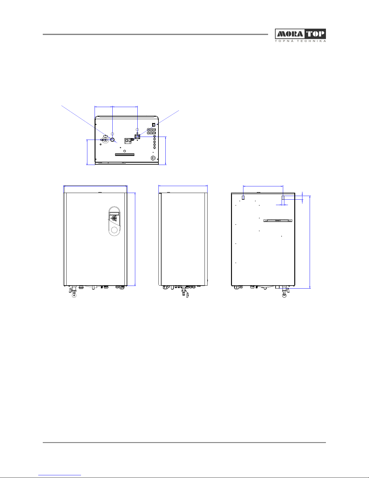
It is necessary to leave a free space on both side
†manual, only by adult person who was posted in
walls of the boiler 100 mm and minimally 400mm maintenance of the boiler. Putting the boiler into
from the top for after sales service. In case that you operation will made by authorized service person
will not observe this request for free space you have during the heating test.
to pay dismantling and mounting the boiler back to Any manipulation, operation, using and maintenance of
the wall and to heating system, it is not a repair paid †
the boiler, which is not in accordance with instructions
in guarantee period! and advices stated in this instruction manual, is
1.3.2 inadmissible. The producer is not responsible for
Putting the boiler into operation has to be carried out
†damages caused by wrong using and maintenance of
only by authorized professional company or service the boiler.
person that has a valid agreement signed with the The producer recommends periodical service controls
†
producer. The list of these companies is enclosed. of the boiler 1x per year before heating season. The
The company or person who will put the boiler into
†service control could be done only by a professional
operation has an obligation to assure repairs of authorized service company or person. The list of
breakdowns or defects in guarantee period. In case that service control steps recommend to be controlled
this company doesn't exist anymore, the guarantee before heating season you will find in the chapter
repair will be assured by any company from the list “maintenance”.
closed to you. The producer allows only room thermostat connection,
†
By putting the boiler into operation the authorized
†if the room thermostat has with potentional-free outlet
person is obligated to: connection. The authorized service person is
†control connections of the boiler to electric supply responsible during putting the boiler into operation to
network and to heating system fill and sign guarantee card.
†control tightness of the boiler If you find any breakdown or any defect on an electrical
†
†control all functions of the boiler part of the boiler, please, don´t repair it by yourself,
†inform the user about boiler operation, its control and disconnect the boiler from the electric supply network
maintenance and ask for after sales service person.
inform the user about safety dimensions from sides of
†It is not allowed to use the boiler Electra-Comfort for
†
the boiler from flammable walls and its protection another purposes than is stated in this instruction
according to ČSN 061008 and ČSN 730823. manual.
To fulfil requests for boiler safety and economic
†
operation it is necessary to observe below mentioned 1.3.4
conditions:
for boiler mounting and installing the user has to get the
†Fire instructions:
permission from the company who is a distributor of Disconnect the boiler from the electric
†
electricity in your region, control the input of the boiler if supply network and take out it out of its
it is in accordance with the input stated in the operation according to possibilities.
permission Extinguish fire using pulverized or
for mounting of the boiler it is necessary to have an
†snows extinguish appliance flammable
authorized technical project for heating system and for and explosive materials
connection of electric boiler Don't stock any flammable and explosive
†
the boiler is able to be mounted only in an environment
†things closed to the boiler (for example
according to its determination and according to the paper, colours, chemicals etc.)
project
Putting into operation
Safety
ELECTRA COMFORT 4
ELECTRA COMFORT 5
450
656
345 280
26
16
652
124 176
177
199
G3/4
34
G /
1.4 Main dimensions
Dimensions in mm.
outlet of heating water
in h tiwter
let of ea ng a
ELECTRA COMFORT 6
1.5 Technical data
2 x 3 x 1,5
Power output of 1 heating rod in kW
3 heating rods
2 x heater
Boiler type ELECTRA 05 ELECTRA 06 ELECTRA 08 ELECTRA 09
Electric parameters COMFORT COMFORT COMFORT COMFORT
Total electric input kW 4,5 6,0 7,5 9,0
Nominal heating output kW 4,5 6,0 7,5 9,0
Heater power output - 3x1,5 3x2,0 3x2,5 2x3x1,5
Nominal current A 3x7,5 / 1x21 3x10x/x1x28 3x12 / 1x36 2x3x1,5***
Electric network* V
Electric network V
Nominal current max. A 3x7,5 / 1x21 3x10x/x1x28 3x12 / 1x36 3x14
Pump input W
Main circuit breaker A 3x10 1x25 3x16 / 1x32 3x16 / 1x40 3x16
Nominal current of control fuse A
Enclosure IP
Mechanical life time of relay -
Electrical life time of relay
Width mm 450 450 450 450
Height mm 656 656 656 656
Depth mm 345 345 345 345
Boiler weight without water kg 36,5 36,5 36,5 38
Min. working overpressure of heating systém bar
Max. working overpressure of heating systém bar
Operation overpressure recommended kPa/bar
Circle pump -
Maximal temperature of heating water °C
Water volume of whole boiler l
Environmental kind ČSN 332000-3 -
Efficiency by nominal output %
Supply cable CYKY** mm
25x1,5 / 3x4 5x1,5 / 3x6 5x2,5 / 1x6 5x2,5
Supply cable AYKY** mm
25x2,5 / 3x6 5x2,5 / 3x10 5x4 / 1x10 5x4
Expansion vessel l
Surrounding temperature °C
Warehousing and transport temperature °C
Electromagnetic temperature -
Humidity %
Measuring accuracy %< 1 < 1 < 1 < 1
Accuracy of boiling water regulation °C ± 1 ± 1 ± 1 ± 1
Regulation type -
Cascade -
Service plug -
Number of boilers in cascade max. -
* Y - connection
**Supply lead has tobe proposed in preference in conformity with the norms.
***
Remote control
with cascade controller
6 PIN
according to the cascade controller
40
Unit
Expanding temperature of thermostat
blocked, opened-closed systém °C
Mechanical parameters
Environmental requests
3x230/400V+N+PE/50 Hz*
1x230V+N+PE/50 Hz
50/60/70
0,315
1 000 000 cycles
250 000 cycles, 16 A, 250 V
0,4
3
100/1
CESAO 3
80
100
10,6
normal AA5, AB5
99
8
0 ÷ 40
-30 ÷ + 70
EN 55014-1(2006)
0 ÷ 90 without condensation
PI
Regulation
ELECTRA COMFORT 7
2 x 3 x 1,5
Power output of 1 heating rod in kW
3 heating rods
2 x heater
Boiler type ELECTRA 12 ELECTRA 15 ELECTRA 18 ELECTRA 24
Electric parameters COMFORT COMFORT COMFORT COMFORT
Total electric input kW 12 15 18 22,5
Nominal heating output kW 12 15 18 22,5
Heater power output 2x3x2*** 2x3x2,5 3x3x2 3x3x2,5
Nominal current A 3x19 3x24 3x28 3x36
Electric network* V
Electric network V - - - -
Nominal current max. A 3x19 3x24 3x28 3x36
Pump input W
Main circuit breaker A 3x20 3x25 3x32 3x40
Nominal current of control fuse A
Enclosure IP
Mechanical life time of relay -
Electrical life time of relay
Width mm 450 450 450 450
Height mm 656 656 656 656
Depth mm 345 345 345 345
Boiler weight without water kg 38 38 39,5 39,5
Min. working overpressure of heating systém bar
Max. working overpressure of heating systém bar
Operation overpressure recommended kPa/bar
Circle pump -
Maximal temperature of heating water °C
Water volume of whole boiler l
Environmental kind ČSN 332000-3 -
Efficiency by nominal output %
Supply cable CYKY** mm
25x2,5 5x4 5x6 5x6
Supply cable AYKY** mm
25x6 5x6 5x10 5x10
Expansion vessel l
Surrounding temperature °C
Warehousing and transport temperature °C
Electromagnetic temperature -
Humidity %
Measuring accuracy %< 1 < 1 < 1 < 1
Accuracy of boiling water regulation °C ± 1 ± 1 ± 1 ± 1
Regulation type -
Cascade -
Service plug -
Number of boilers in cascade max. -
* Y - connection
**Supply lead has tobe proposed in preference in conformity with the norms.
***
Unit
50/60/70
0,315
Mechanical parameters
1 000 000 cycles
40
0 ÷ 90 without condensation
Regulation
Expanding temperature of thermostat
blocked, opened-closed systém °C 100
10,6
normal AA5, AB5
99
3x230/400V+N+PE/50 Hz*
8
0 ÷ 40
-30 ÷ + 70
EN 55014-1(2006)
Environmental requests
0,4
3
100/1
CESAO 3
80
250 000 cycles, 16 A, 250 V
PI
Remote control
with cascade controller
6 PIN
according to the cascade controller
ELECTRA COMFORT 8
1.6 Main parts
boiler heating sensor emergency thermostat
mode relay
mode sanitary water
control unit holder
display
touch control buttons
control unit
frame of the boiler
switchboard X2
switchboard X1
safety valve
expansion vessel
thermomanometer
sensor
cables bushing
main switcher on/off
pump
pressure switcher
inlet pipe
safety contactor
thermomanometer
control panel
insulation of boiler
body
reservoir of emergency
thermostat
heating elements
deaerate valve G3/8”
boiler body
Control unit has several functions which assure basic
1.7 characteristics, mainly:
safety functions assure protection against the of health
†
1.7.1 and property
The boiler is designed according to valid norms and rules user's functions functions set by the user
†
ČSN EN and IEC. The safety of the boiler, energy saving operation functions internal functions of control unit
and sound was important matter during the boiler †
designing. import for sound operation of the boiler, but un-get-at-
able for the user
1.7.2 Principle of boiler operation Control unit could be in below mentioned modifications:
The insulated boiler body with volume 10,6 l is a reservoir basic only for heating = control unit + mode relay
†
where water is heated by electric heating elements for heating and heating of sanitary water = control unit
†
according to the boiler type, by one (05 kW, 06 kW and 08 + mode relay + mode TUV (sanitary water)
kW), two (09 kW, 12 kW and 15 kW) or three (18 kW and for heating with GSM remote control = control unit +
24 kW). Depending on the actual heat requirement, †
individual heating rods are connected, each of them mode relay + mode GSM
having a power output of 1,5 kW for Comfort 05 and for heating and heating of sanitary water with GSM
†
Comfort 09 (1 heating rod = 1,5 kW, 6 heating rods 9 kW), remote control = control unit + mode relay + mode TUV
a power output of 2 kW for Comfort 06, Comfort 12 and (sanitary water) + mode GSM.
Comfort 18 (1 heating rod 2 kW, 9 heating rods 18 kW) or a
power output of 2,5 kW for Comfort 08, Comfort 15 and Control unit works with below mentioned inlet signals:
Comfort 24 (1 heating rod = 2,5 kW, 9 heating rods 22,5 temperature of heating water (sensor NTC)
†
kW). Circulation of water is through the pump. Safety of outside temperature (sensor NTC)
†
boiler operation is monitoring by several independent
sensors. Whole heating process and pump operation is room temperature (sensor NTC)
†
controlled by the control unit with display and push touch temperature of sanitary water (sensor NTC) only if the
†
control buttons. The button 0/1 is for switching off the boiler has connected TUV (sanitary water) sensor
boiler out of operation. switching on signal of sanitary water heating 230 V
†
(only if the boiler has TUV (sanitary water) mode
1.7.3
Decription of function
Technical description
Control unit and control board
ELECTRA COMFORT 9
blow off valve of the boiler
body
outlet of heating wate
(warm)G 3/4”
outlet of safety valve blow off valve of th
pump
inlet of heating water
(cold) G 3/4”
1.7.5 Safety function of the boiler
room thermostat signal potentional free switcher
†
signal of relay lightening in the first level potentional
†Control unit
free switcher The control unit is designed according to valid EU norms
†
signal of relay lightening in the second level
†and is certified.
potentional free switcher The control unit has a protection against below and
†
HDO (mass remote control) signal potentional free
†over voltage
switcher The control unit is protected by system Watch-Dog-
†
signal HDO (mass remote control) activation of
†Timer with time 512 ms against its processor “blocking”.
“working zero” N In case that the processor is blocking the automatic
breakdown signal of floor overheating potentional
†reset function is activated and then the program is
free switcher going with all parameters set from the point where it
breakdown signal of overheating 230 V was broken
†
breakdown signal of pressure loss 230 V
†
Protection against overheating
signal of GSM mode
†The boiler has an emergency thermostat set for 100 °C.
†
In case of boiler overheating heating elements are put
Control unit controls: out of operation independently to the control unit. This
mode relay heating elements
†breakdown is signaling on the display as a critical
mode relay pump
†breakdown No. 5.
mode TUV (sanitary water) three ways valve for TUV This breakdown could be repaired only by authorized
†
service man.
Protection against lost of heating water pressure
1.7.4
The boiler equipped with a pressure switcher which
†
Antifreeze protection of the boiler control minimal pressure in heating system 0,4 bar,
when the function reliability of deaerate valves is
This function protects the boiler against freeze and is
†assured, it means that the boiler has sufficient volume
active in the mode STAND-BY. of water.
Circulation pump and the boiler are in operation, if
†In case of lost of heating water pressure below 0,4 bar
†
temperature of heating water decreases below 5 °C. In the boiler signs the critical breakdown No. 4 and
this case the boiler assures minimal level o heating and heating elements are put out of operation
the system is mildly warm, the boiler heats to 15 °C independently to the control unit.
temperature of heating water and after that the boiler
set back to mode that it start to operate from. Pump This breakdown could be repaired after the control of
†
running of is active. tightness of water ways and after water filling over 0,4
bar. After that the boiler is automatically reset and
In case that the boiler is in the summer mode
†returned to normal operation.
(permanent heating of storage water tank) and the
temperature of heating water decreases below 5 °C Boiler protection against over and below voltage
then the antifreeze protection function is activated for in supply electrical net
heating system, after the boiler catch the temperature
15 °C, then the 3-ways valve go back to the position for The control unit is equipped with function assuring
†
heating of sanitary water and pump running of is also putting the boiler out of operation if the voltage is below
active. 150 V or over 250 V. This stage is marked on the display
like a critical breakdown No. 8. Below voltage is not
If the boiler is switched off or out of marked on the display.
electric supply, this function is not active.When the voltage is OK = in the scale 150 250 V, the
†
boiler returns to normal operation.
Unlocking protection of heating system Boiler protection against overpressure of heating
It is active at all times if the circulation pump or 3-ways
†water
valve is more than 24 hours out off operation to protect The boiler pump is equipped with pressure safety valve
blocking of the pump or the valve due to its small parts. set for 3 bars. In case of the overpressure more than 3
This function avoids blocking of the pump rotor in mode bars the leakage of water occurs from the valve till the
STAND-BY and elongates its lifetime. pressure of water in heating system is not below
maximal requested level.
The pump works 1 time per day for 10 s.
†This valve is in its operation automatically.
Antifreeze protection of the boiler
ELECTRA COMFORT 10
ELECTRA COMFORT 11
rui fo onne to toe K, K2 to uppl eet a 2 V 00
Ci c tdiagram r c cin of he b il r EK18 E 4K s y l cric l net 3x 30 /4 V
1.8 Circuit diagram
eLeg nd:
V
NTC O -NTC sensor heating water
UNTC O T - NTC outside temperature sensor
NTC ROOM - NTC room temperature sensor
R
TE - room thermostat 24V
FLOOR - fr
underloo heating
nd
a h v
2.ST - extern l input lig tening control 2 le el
t
s
ul1.ST - external inp t lightening control 1 leve
-HDO s
mas remote controlí
GSM - GSM modem
e
HT - mergency thermostat
TS -pressure switcher
TUV - service utility water (sanitary water)
o
KM1 -contact r
switchboard
X1, X2 -
i
HV - ma n switcher
Č - pump
ZM - earthing bridge
t i
PE - proectve conductor
o
N - working” conductr
u
L -phase condctor
g e
TT1 - heatinlement 1
g el
TT2 - heatinement 2
el
TT3 -heating ement 3
L
N
PE
TS/230V
HT/230V
0HDO/23 V
HDO
FLOOR
2.ST
1.ST
TER
NTC OV
NTC OUT
O
NTC ROM
135
A1
2462
A
T
T 1
TT2
TT3
L1
L2
L3
N
PE
15
1a10a
1
1b
TT1.3
TT2.3
TT3.3
TT1.2
TT22
TT3.2
TT1.1
TT2.1
TT3.1
PUMP
mode relay
control unit
KM1ČZM
TS
HT
C
X2 1X
HV
21
0
NC NO
L1L2L3NPE
1
2
1
PG2
L
Service
M
GS
TUV
REL
cne tion i h control nti.
onc w t u
Remarks: clamps 24 V of the room thermostat ar
d g fe
connecte throu h rom th factory
c
Conne tion TUV ZOV (sanitary water, storage water tank)
i ,
sw tchboard X2, clamps 2a 10a.
N
10
.
TT1 3
.
TT12
.
TT11
TT2.3
TT2.2
TT2.1
TT3.3
TT3.2
TT3.1
ELECTRA COMFORT 12
Ci c i m f o ne o e l r K K 1, K s y e ei a x 3Vr ut diagra or c nction f th boi e E 09 ,EK 2K EK 15 to uppl l ctr c l net 3 20/400V
d
Legen:
N C O
T V -r t wa
NTC senso hea ing ter
NO e p a res rTC UT - NTC outside t m er tu sen o
O-C m t r
NTC ROM NTroo empeature sensor
TER - hot4room termsat 2V
O
FL OR -f o ha
under lo r e ting
nd
Setail n c nl e e
2. T - x ernl nput ightenig o tro 2 l v l
ts
1 eu h n l
.ST- ext rnal inp t lig te ing control 1 evel
OHD - ol
mass remte contro í
GSM - GSM modem
Tm g c e m
H - eer en y th r ostat
su r
TS-pres re switche
TV-e ilinitU servicut ty water (sa ary water)
1-o
KM contactr
2 - sthor
X1, X wi c bad
V - a n c
H m i swit her
Č - pump
ZeigM - arthn bridge
Pv o do
E - protectie c n uctr
” dc oN - workingconut r
-enu rL phas codcto
TT1- h ating emet 1 ele n
T2 h atin el me t 2T - e g e n
Remarks: clam s 24 V of t e room therm tat ar
ph os
connected through f m the facto
ro ry
Connection TU ZOV (sanitary water, storage wter tank)
V a
switchbord X2, clamp 2a, 8a.a s
nt o ntco r l u i
m de relayo
co ne io i oronin ct n w th cntl ut.
ELECTRA COMFORT 13
io e h 05 , 0 p t l n VCircu t diagram f r conn ction of t e boiler EK K Ek 06K, EK 8K to su ply elec rica et 3x230V/400
e n
Lge d:
NTC OV -Ns a i
TC ensor he tng water
Tempe ur
NTC OUT - NC outside trat e sensor
Cper ens
NT ROOM - NTC room tem ature s or
TER - o t st t
r om hermo a 24V
O
FLO R - nr o eig
u de flo rhat n
nd
ex i ng c l el2.ST -ternal input l ghteni ontrol 2ev
st
ter ni ontr ev
1.ST - exnal input lighte ng c ol 1 l el
HDO -msr m t n r l
as e o e co toí
GSM - SmdG M o em
TostH - emergency therm at
S e sw
T-pressur itcher
V -rilyt a wTU sevice utit wa er(s nitary ater)
MoK1 -c ntactor
X1, i c ad
X2 - sw t hbo r
V - sch
H main witer
-m
Č pup
-r
ZM ea thing bridge
E -ve co u oP protecti nd ctr
Nn co u o
- worki g” nd ct r
h n ctrL -p aseco du o
T1 - heat ng el ment 1
T ie
m r : ms 2 V t r o e m sta a
Re a ksclap4 ofhe o m th r o t r
nct d r ug f om t fctoycone e tho h r he a r
n ct n T VZV ( nr wa r, toag w er tak)Co ne io U Osaitay te sre at n
witcor X , m s a,.
s hba d 2 cla p 2 6
contr l uito n
onne on i ol it.c cti w th contr un
ELECTRA COMFORT 14
io e h 05 , E ly e e
Circu t diagram f r conn ction of t e boiler EK K EK 06K, K 08K to supp lectrical n t 1x230V
egenL d:
N
TC OV -Ce or ti wa
NT s ns hea ng ter
N T - NT e tper ur nso
TC OU C outsid em at e se r
N C OO Cr teer r nso
T RM - NT oom mp atu e se r
-
TER m the s 4V
roormotat 2
O
FL OR -r oor ati
undefl he ng
nd
. xterl i puenin tr leve
2 ST - ena n t lightg con ol 2 l
st
e na li ht co ol 1 leve
1.ST -xterl input g eningntrl
H O
D -m s e ol
as r mote contr í
GSM - SM mod
Gem
c thmo
HT - emergen y er stat
p e su e sw
TS -rs r itcher
V cutly er( arwat )
TU - servie i it wat sanity er
M1 -K contactor
, - s i d
X1 X2 wtchboar
V n w tc rH-mai s i he
mp
Č - pu
ZM - thig br d
ear nige
PE - ptec e c ndu tor
ro tivo c
- wkn c uc r
N or i g”ond to
-ph e c ndu tor
Las o c
TT1 - heating e eme t 1
l n
Remark cl ps 24 oft r om t mst
s:am V he o heroat ar
onnected thro f om the actory
cugh r f
Connecton TUV V sanit y er stage a er t )
i ZO (ar wat , or wt ank
swichboard X2, camps 6.
t l 2a,
cotrol unit
n
mod re ay
e l
iw c uconnect on ith ontrol nit.
ELECTRA COMFORT 15
Circuit diagram TUV ZOV (sanitary water, storage water tank) of the boiler EK 24K
Legend:
O a rNTC V -NTC sensor he ting wate
NTC OUT - NTC outside temperature sensor
oNTC ROOM - NTC rom temperature sensor
t
TER - room thermosta 24V
FLOOR - underfloor heating
nde
2.ST - external input lightening control 2 levl
st
ao
1.ST - externl input lightening c ntrol 1 level
c
HDO -mass remote ontrolí
MGSM - GS modem
HT - emergency thermostat
TS -pressure switcher
e a rTUV - s rvice utility w ter (sanitary wate )
KM1 - ontactorc
X, X2 - sitch ar
1 w bo d
HV - main switcher
Č - pump
M - earthirdge
Zng b i
E - r ctive c nductor
P p ote o
N - orking cductor w ” on
L - hase cond tor
puc
T eti g lee t T1 - h a n e mn 1
TT eti lee t 2
2 - h ang e mn
T - e tin e e 3
T 3 h ag elmnt
ks: a s V t r oth o t aRemar cl mp24 of he o m erm sat r
n cteh o o f re
cone d tr ugh fr mtheacto yConnction TUV ZOV
(nt y a t a n
sa i ar w ter,s orage w ter ta k)
ibr Xc m 0
sw tch oad2, la ps 2a, 1 a.
co r l
nt o unit
meod relay
o ne ti w th o r l it
cnc oni c ntoun .
THER.TUV
1 2 N L3
orange
green
PE
Not included
Connection of DHW tank thermostat
TUV
Module TUV
Connection control unit
TMV
TMV -three way vale
ELECTRA COMFORT 16
2.
2.1
Maintenance
Control panel
information display
- temperature setting in
the reference room
change of the requested
parameter -
change of the requested
parameter +
- sanitary water temperature
setting
- information about
instantaneous stage
- going to mode STAND-BY
- parameters enter
- selection confirmation
i
0
0 C 0
--0 C
0
--0 C
ZI
22,5 kW
- going from the mode
STAND-BY the mode of heating
+
-
Thermomanometer
ELECTRA COMFORT 17
Display
- Information display
-use for editing of instantaneous values of the electric boiler
-enter to information display is available after long (approx. 4s) pushing or 4x short pushing
0
TVS + 10 C 0
OVP35 C
CSQ:20 PP:3
instantaneous temperature of outside sensor
only if it is connected( )
requested and calculated temperature of the heating water
according to an equithermic curve( )
last breakdown in the boiler memory
GSM signal intensity (1- 30)
only if GSM mode is connected( )
- Basic information displayed
0
40 C 0
55 C 0
21 C
WI
10 kW
instantaneous temperature
of heating water
instantaneous temperature of sanitary
water in the storage water tank
only if the boiler has TUV (sanitary water) mode
and TUV (sanitary water) sensor connected)
(
instantaneous temperature in referring room
in case of reffering room sensor connection)(
pump operation
marking is lightining and the pump is in an operation
marking is not lighting and the pump is switched off
-
-
signalizing of instantaneous stage of the boiler
-
( )
-
the boiler is in an operation of storage water tank heating
only if the boiler has TUV mode
the boiler is in and operation of heating water
signalizing of instantaneous stage of GSM
only if the boiler has GSM mode
GSM in an operation
receiving/sending SMS
( )
- -
- @ -
signalizing of the instantaneous boiler mode
mode “WINTER” (heating water and
storage water tank heating)
mode “SUMMER” (only storage water tank heating,
if the boiler has TUV (sanitary water) mode connected)
WI -
SU -
instantaneous output
of the boiler in kW
- S - (Soft start) SOFT START - see parameter P11
temperature of heating water using the button - below
2.3 Modes 25° C and confirmed this by .In this operation mode
the boiler is heating only the storage water tank (3-
Important information for setting ways valve is permanently in position in position
during editing “help” is lighting in the low line for the “tank”). It is possible to go from this operation mode to
†
value to be set operation mode “Winter” by increasing of heating water
temperature using and confirm it by .
during the first pushing of each button the editing is not
†
active Operation mode “stand by”
in delay in setting more than 10 s the editing is without
†on the display there is
†
the change, it means that the setting is going back to
this operation mode is activated by long pushing (3 s)
the starting position (only if the editing was not †
confirmed ) the button and deactivated by short pushing .
each value set has to be confirmed by button . Concerning this operation mode there are only active
††
protective functions described in the chapter 1.7.4
if the value setting is not wanted or wrong (for example
†
entering the parameters setting), wait 10 s and the 2.3.1 Mode heating (heating water)
boiler is automatically going back to starting basic
display or it is also possible to “enter” the parameter by
pushing the button , . on the display there is the symbol
†
By holding the button , the setting value will
†this manual mode is active in operation mode
†
automatically rolls up or down “WINTER” “WI”“
In case of wrong parameters setting it is possible to go
†
back to “factory setting” according to these steps:
switch off the boiler using the main switcher, push
together and switch on the boiler. On the
display there is “reset of factory parameters” and after
OK is displayed then the parameters are according to
factory setting.
Main operation modes
Operation mode “winter”
on the display there is “WI”
†
this operation mode is active always when the
†
temperature of heating water is set (it means the
operation mode “SU” is not lighting). In this operation
mode the boiler is heating the system and also the
storage water tank (if it is connected through)
Operation mode “summer”
on the display there is “SU”
†
this mode is possible to activated by reducing the
†
+-
+-
+
ELECTRA COMFORT 18
2.2 The boiler switching ON/OFF
Use the switcher 0/1 placed on the right corner of bottom side of the boiler (see the picture 1.6 Main parts)
On the display there is displayed introductory information after boiler's switching on.
E - KOMFORT: 22,5 kW
TUV: NE VER.1.20
- electric boiler ELECTRA comfort with output 22,5 kW
- TUV mode is not connected, SW version 1.20
Switchboard of the boiler and inlet conductors and clamps of the contactor and inlet conductor
of the switcher are under voltage!
Disconnect the boiler from the main electric inlet supply!
Example::
ELECTRA COMFORT 19
Without the room thermostat connected With the room sensor connected (on the display there is
marked by the symbol .
In case that the room sensor is connected (the order
number of set is 4050485) the boiler is heating according
to the temperature in a reference room with hysteresis 1
°C. Actual temperature in the reference room is displayed
under the symbol .The room sensor is connected on the
clamps of the control unit marked NTC ROOM.
Steps for setting of temperature in a reference room
Press the button , on the control panel, for setting of the
temperature requested press for its increasing or
for its decreasing and confirm it by . After this
confirmation you will go back to main display.
Temperature could be set in scale from 5 to 35 °C, if the
temperature is decreased below 5°C the regulation
function is switched off on the basis of reference room
temperature. The boiler is controlled by the same way as
in previous 2 samples without the importance of the
temperature in reference room. The temperature will not
Regulation is depended on the temperature of boiler water be shown on the display.
requested by the user and hysteresis set by the parameter Remarks: if you have reference room temperature
P20 in the scale 1 - 10 °C. (This parameter could be set regulation activated then this regulation is priority (and
only by authorized service person). the boiler will not reply to room thermostat).
Steps for temperature setting of heating water:
Set the temperature requested by pushing , on the
control panel , on the display is temperature and “OV
TEPLOTA” and confirm by .After confirmation you will
go back to the basic display. The boiler is now heating to
the temperature requested by you. The scale of
temperature setting is 25 80 °C (regarding the setting
below the temperature value 25 °C the marking of
operation mode “SUMMER” = “SU” is lighting, going back
to heating mode is possible only by increasing the
temperature of heating water by the button ) .
If you don't confirm the value during editing till. 10 s, the
boiler is automatically goes back to the previous setting.
We recommend you to use the room thermostat for
economical operation of your heating system
With the room thermostat Steps for setting of temperature in a reference room with
GSM modem(Only if you have GSM modem order No.
9566.2010 connected to the boiler)
The temperature in a reference room it is possible to set
also like a remote control through SMS in a format
example *22 (star, temperature in °C without spaces)
according to the way described in a instruction manual of
GSM modem.
With equitermic regulation
equitermic regulation is not depended on instruction
†
from control elements of the boiler, it is determined
only for setting the temperature of heating water on
the basis of outdoor temperature.
In case that the room thermostat is connected the this mode it is possible to be activated by connection of
†
regulation of temperature is the same as in case outdoor sensor (set of outside sensor order No.
without the room thermostat connected till the moment 4841815 of control unit “NTC OUT”) and setting of
when the request for heating is stopped by the room equitermic curve regulation is done by the parameter
thermostat.
GSM module works only in the nets with
standartized GSM protocol.
+-
+
+-
4
55
6
1 -
4 -
5 -
6 -
boiler
heating system
closing valve
filter
1
1 -
4 -
5 -
6 -
10 -
boiler
heating system
closing valve
filter
temperature sensor
in reference room
4
55
6
10
1
9
4
55
6
1 -
4 -
5 -
6 -
9 -room thermostat
boiler
heating system
closing valve
filter
1
ELECTRA COMFORT 20
With connection of TUV sensorP8. Temperature of heating water for heating will be
automatically calculated on the basis of the outdoor
temperature according to the curve chosen and change
of starting point (parameter P9) without dependency of
heating water temperature setting.
Steps for setting are described in a chapter “Setting of
parameters”.
Disconnecting of equitermic regulation is necessary to
carry out with the parameter P8 and with decreasing of
the equitermic curve number value under the value “1”
till the text “NE” is displayed.
2.3.2 Mode TUV (sanitary water) is displayed
This mode is able to be activated after connection of
†
TUV mode order No. 9566.2000,
This mode is active in operation mode “summer”,
†
“winter” and is activated after request for heating
into the storage water tank.,
Temperature of water in the storage water tanks is
†
controlled directly by connection of TUV sensor in
the TUV mode or indirectly with storage thermostat
which gives information to the boiler heat/don´t heat
through the connection of connection of contactors
to the clamps on the mode TUV. 1 -
2 -
3 -
4 -
5 -
6 -
7 -
boiler
storage water tank
3-ways valve
heating system
closing valve
filter
back flap
8 -
9 -
10 - reference room
temperature sensor
11 -
12 -
13 -
14 -
treatment place
for water
room thermostat
consumption place
safety valve for TUV
(sanitary water)
expansion valve
sensor of storage
water tank
9
M
AB
A
B
13
2
3
4
56
7
8
11
12
14
55
5
5
10
1
Below mentioned equitermic curves are calculated for room reference temperature 20 °C.
curve No.
1
2
3
20
25
4
5
6
7
9
10
65
70
75
80
85
30
35
40
45
50
55
60
4
5
678
9
10
1
2
3
outside temperature (°C))
temperature of heating water (°C))
equitermic curves of control panel
curve No.
curve No.
curve No.
curve No.
curve No.
curve No.
curve No.
8
curve No.
curve No.

This manual suits for next models

7

Popular Boiler manuals by other brands

Ferroli TEMPRA 30 Installation, service and user instructions

Ferroli

Ferroli TEMPRA 30 Installation, service and user instructions

broag remeha Gas 3c ECO technical information

broag

broag remeha Gas 3c ECO technical information

Cerbos QUAD 10 User and service manual

Cerbos

Cerbos QUAD 10 User and service manual

Lennox MGC Series Installation, operation & maintenance manual

Lennox

Lennox MGC Series Installation, operation & maintenance manual

Sime SOLIDA 5 PL manual

Sime

Sime SOLIDA 5 PL manual

ACV Compact N1 manual&nbsp;

ACV

ACV Compact N1 manual&nbsp;

tepeo ZEB-40R Installation and user manual

tepeo

tepeo ZEB-40R Installation and user manual

Lochinvar Crest FBN 2500 Supplemental manual

Lochinvar

Lochinvar Crest FBN 2500 Supplemental manual

ACV The Challenger User's information manual

ACV

ACV The Challenger User's information manual

Kostrzewa Twin Bio user manual

Kostrzewa

Kostrzewa Twin Bio user manual

AFK HWD-9 instruction manual

AFK

AFK HWD-9 instruction manual

Elgena KB 6 Installation and instructions for use

Elgena

Elgena KB 6 Installation and instructions for use

Baxi PRIME Series installation manual

Baxi

Baxi PRIME Series installation manual

Carrier BW9 Series User's information manual

Carrier

Carrier BW9 Series User's information manual

Vaillant ecoTEC exclusive 832 Installation and maintenance instructions

Vaillant

Vaillant ecoTEC exclusive 832 Installation and maintenance instructions

Daikin ROTEX GW-20 H12 installation instructions

Daikin

Daikin ROTEX GW-20 H12 installation instructions

Viessmann VITOCROSSAL 200 Service instructions for contractors

Viessmann

Viessmann VITOCROSSAL 200 Service instructions for contractors

RBI FUTERA II Series User's information manual

RBI

RBI FUTERA II Series User's information manual

manuals.online logo
manuals.online logoBrands
  • About & Mission
  • Contact us
  • Privacy Policy
  • Terms and Conditions

Copyright 2025 Manuals.Online. All Rights Reserved.