6Genuine OEM Parts 1.800.233.4823 www.morganolsonparts.com 7
USPS 2 Ton Delivery Vehicle 2016 - 2018 Models
CONFIDENTIAL NOT FOR DISTRIBUTION CONFIDENTIAL NOT FOR DISTRIBUTION
CONFIDENTIAL NOT FOR DISTRIBUTION CONFIDENTIAL NOT FOR DISTRIBUTION
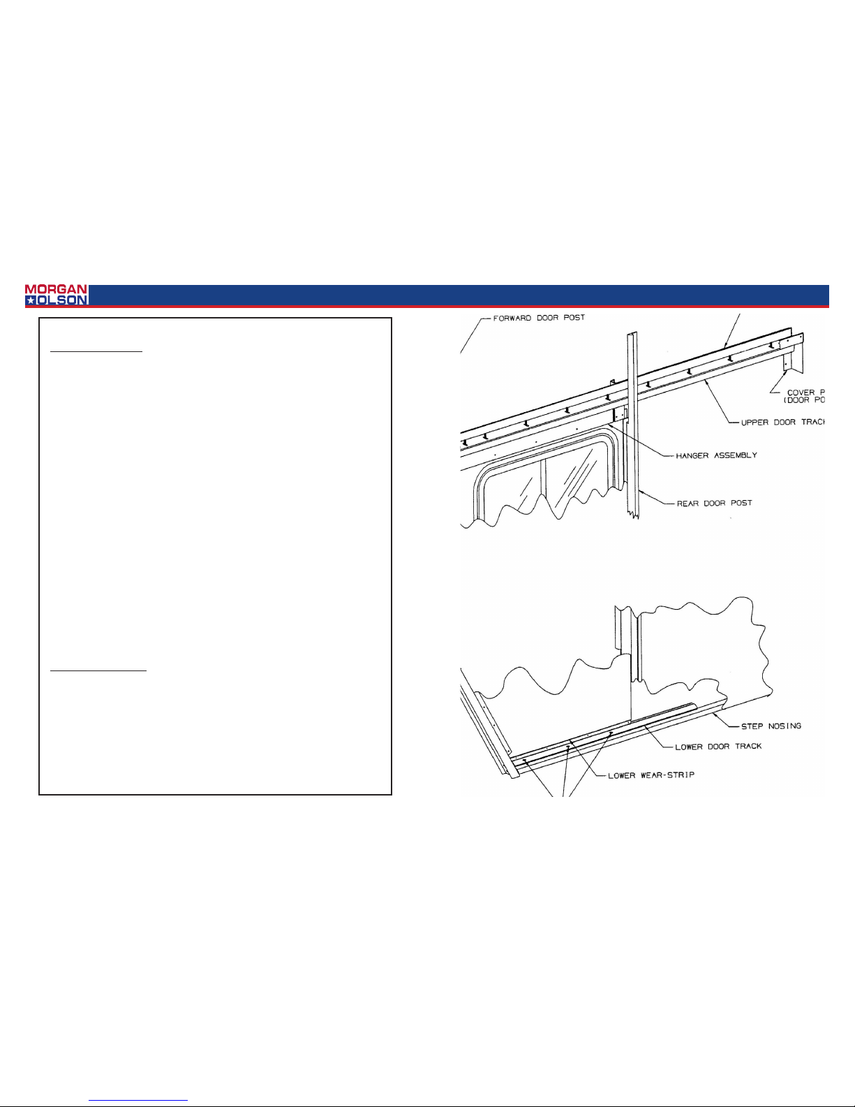
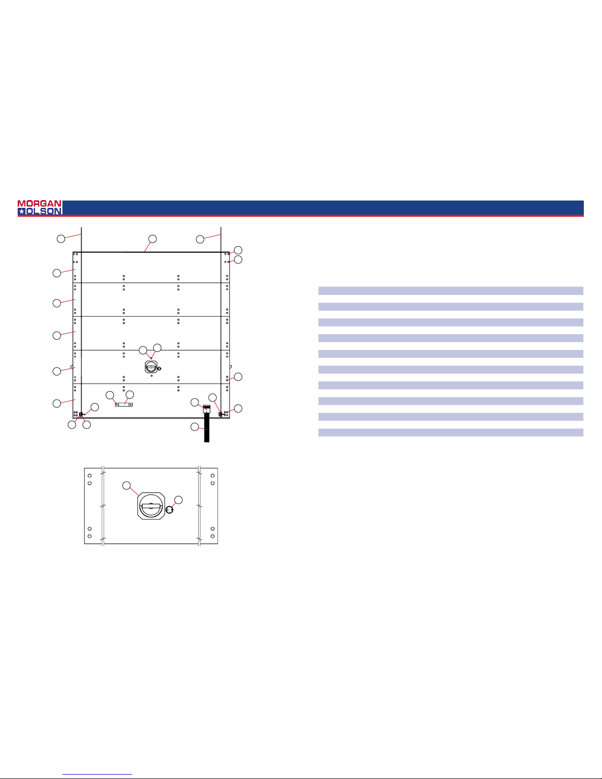
Side Door Removal:
1. Remove screws fastening down the lower door track but leave the track in posion.
2. Remove the Phillips screws and door pocket cover plate located in the upper rear corner
of the door pocket.
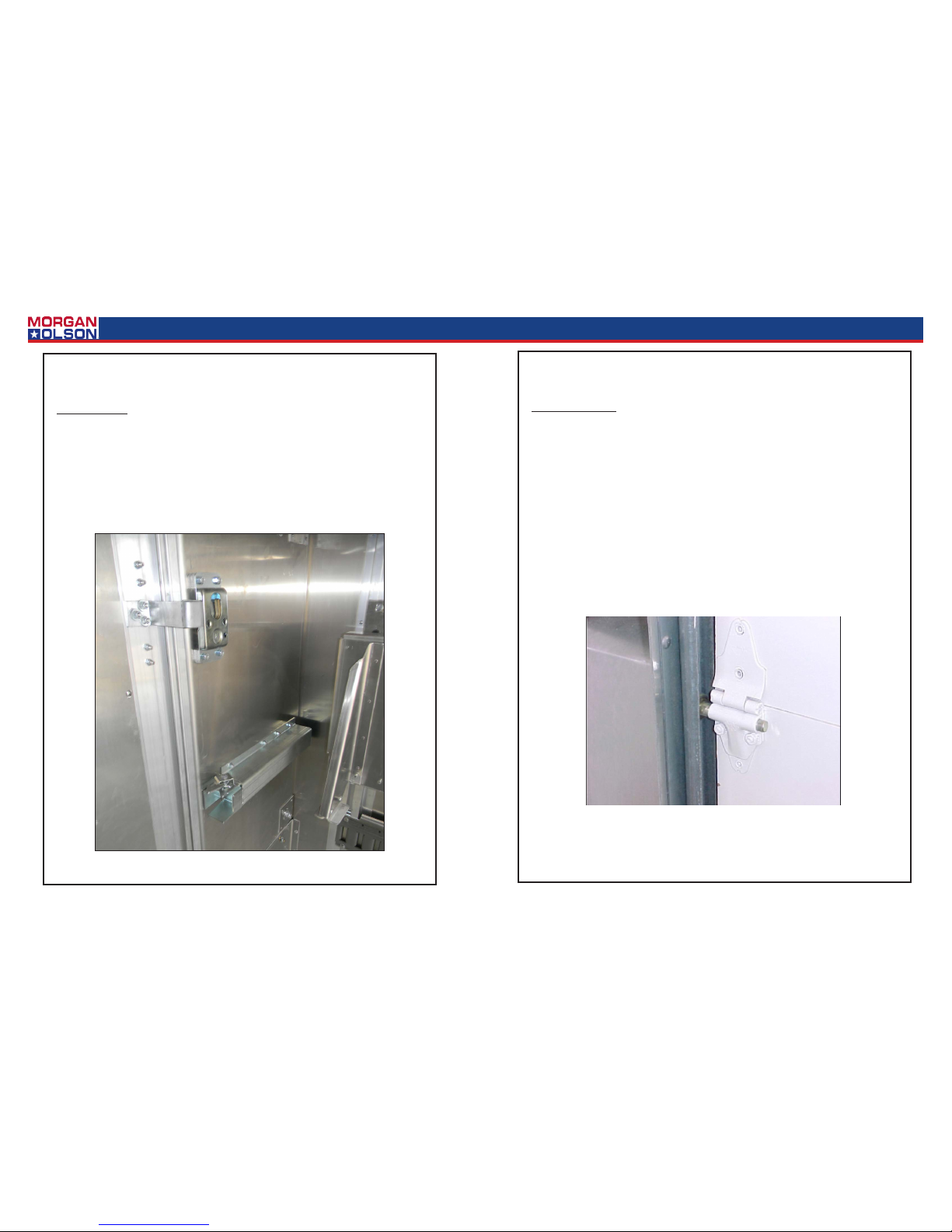
3. Remove the 4 fasteners and the door handles (inner and outer).
4. Using a socket wrench, remove the bolts fastening the door and hanger assembly.
5. To simplify door removal, remove the grab handle located forward of the door.
*Fold side view mirror back.
6. Holding the top of the door in posion, pull out on the boom front corner of the door
unl it clears the body of the truck. Then lt the top of the door down and out and re-
move the door.
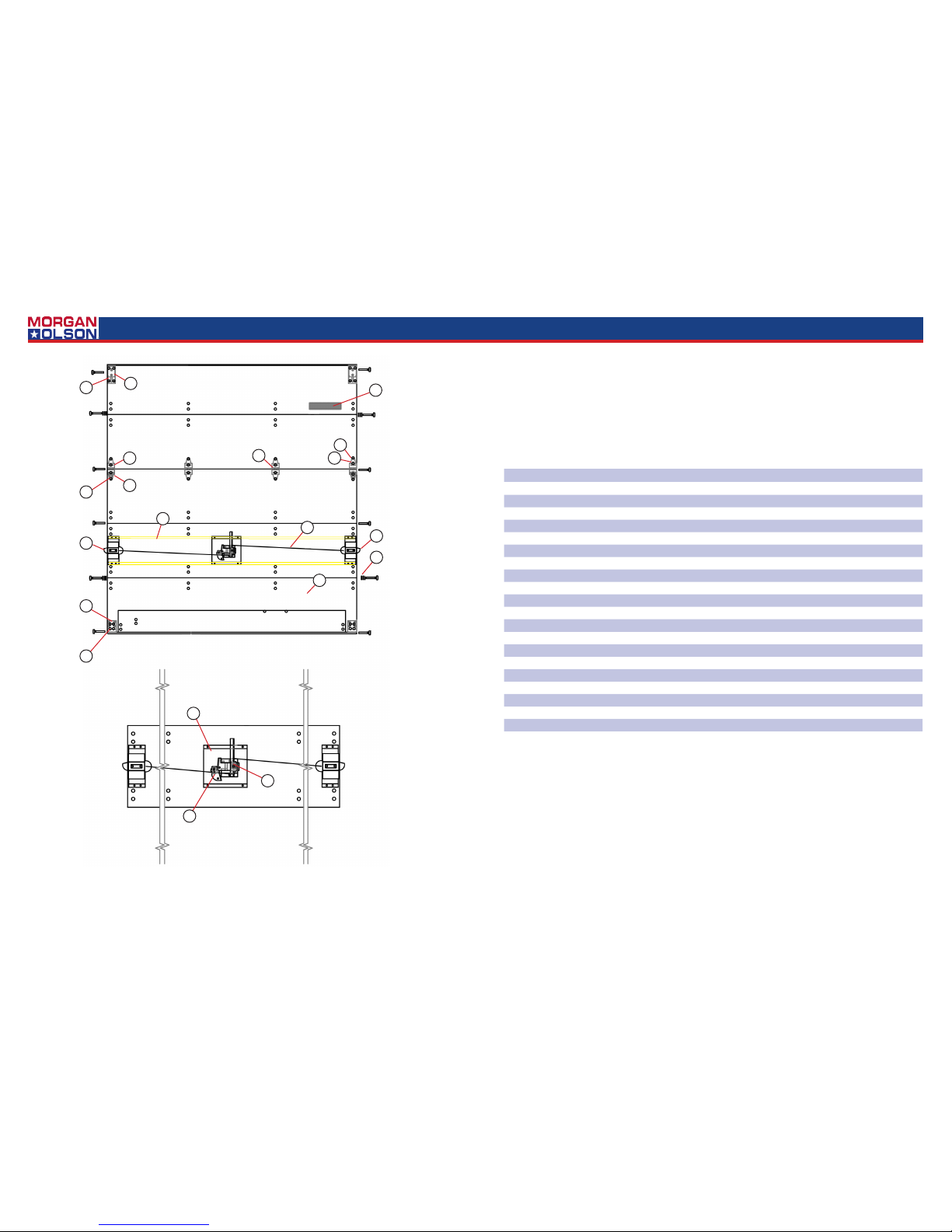
Weather Seal Removal:
1. The forward and rear weather seals are installed simply by sliding into a mated part. To
remove simply pull straight out from the top of the door or door frame. Install by feeding
into the mated part and sliding into place.
Handle Mechanism Removal:
1. To remove the door handles simply remove the 4 mounng screws. Pay special aenon
to spacer locaons. You can then remove the inside and outside handles. Remember
when installing the handles, posion of the spacers idencal to the way they were at
removal.
Door Track (Upper) Removal:
1. The upper track is mounted to the header channel. Remove the nuts, and the track. Rein-
stall by reversing the removal sequence.
Wear Strip (Lower) Removal:
1. Remove side door.
2. Remove exisng rivets.
3. Replace wear strip and rivet in place.
Side Door Installaon:
1. Tilt the top of the door in place rst. Now posion the boom of the door into the lower
door track, which is in posion but not fastened down.
2. Put 1/8” shims between the lower door track and the wear strip.
3. Mount door to the hanger assembly.
4. Install door handles. See page 8.
5. Mount cover plate on upper rear door pocket.
6. Mount grab handle forward of door. *Re-adjust mirror.
7. For proper door adjustment see page 10.


 Operator's manual")


