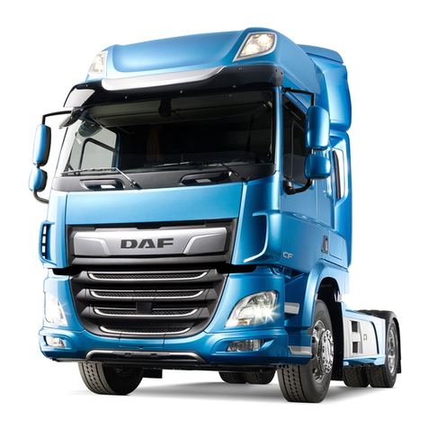
Paccar DAF CF 2017 User manual

Emergency response guide CF > 2017
A PACCAR COMPANY DRIVEN BY QUALITY


©202027 DW83216401
©202027 DAF Trucks N.V., Eindhoven,
The Netherlands.
In the interest of continuing product development,
DAF reserves the right to change specifications
or products at any time without prior notice.
No part of this publication may be reproduced
and/or published by printing, by photocopying, on
microfilm or in any way whatsoever without the
prior consent in writing of DAF Trucks N.V.


STRUCTURE
©202027
1
Structure
EMERGENCY RESPONSE GUIDE


©202027 1
Table of contents
EMERGENCY RESPONSE GUIDE
1
Emergency response guide
TABLE OF CONTENTS
Page Date
1. SECURING THE VEHICLE . . . . . . . . . . . . . . . . . . . . . . . . . . . . . . . . . . . . . . . . . 1-1 . . . . . 202027
1.1 Switching off the engine . . . . . . . . . . . . . . . . . . . . . . . . . . . . . . . . . . . . . . 1-1 . . . . . 202027
1.2 Main switch . . . . . . . . . . . . . . . . . . . . . . . . . . . . . . . . . . . . . . . . . . . . . . . . 1-2 . . . . . 202027
1.3 Batteries . . . . . . . . . . . . . . . . . . . . . . . . . . . . . . . . . . . . . . . . . . . . . . . . . . 1-4 . . . . . 202027
1.4 Airbag . . . . . . . . . . . . . . . . . . . . . . . . . . . . . . . . . . . . . . . . . . . . . . . . . . . . 1-5 . . . . . 202027
1.5 Fluids . . . . . . . . . . . . . . . . . . . . . . . . . . . . . . . . . . . . . . . . . . . . . . . . . . . . . 1-6 . . . . . 202027
1.6 Regeneration unit . . . . . . . . . . . . . . . . . . . . . . . . . . . . . . . . . . . . . . . . . . . 1-8 . . . . . 202027
2. STABILISING THE VEHICLE . . . . . . . . . . . . . . . . . . . . . . . . . . . . . . . . . . . . . . . 2-1 . . . . . 202027
2.1 Seat adjustment. . . . . . . . . . . . . . . . . . . . . . . . . . . . . . . . . . . . . . . . . . . . . 2-1 . . . . . 202027
2.2 Air suspension chassis . . . . . . . . . . . . . . . . . . . . . . . . . . . . . . . . . . . . . . . 2-3 . . . . . 202027
2.3 Cabin suspension . . . . . . . . . . . . . . . . . . . . . . . . . . . . . . . . . . . . . . . . . . . 2-4 . . . . . 202027
3. RELEASING A TRAPPED DRIVER . . . . . . . . . . . . . . . . . . . . . . . . . . . . . . . . . . 3-1 . . . . . 202027
3.1 Cabin types . . . . . . . . . . . . . . . . . . . . . . . . . . . . . . . . . . . . . . . . . . . . . . . . 3-1 . . . . . 202027
3.2 Cabin bracket collision ability . . . . . . . . . . . . . . . . . . . . . . . . . . . . . . . . . . 3-2 . . . . . 202027
3.3 Cabin dimensions . . . . . . . . . . . . . . . . . . . . . . . . . . . . . . . . . . . . . . . . . . . 3-3 . . . . . 202027
3.4 Opening the front panel . . . . . . . . . . . . . . . . . . . . . . . . . . . . . . . . . . . . . . . 3-5 . . . . . 202027
3.5 Doors . . . . . . . . . . . . . . . . . . . . . . . . . . . . . . . . . . . . . . . . . . . . . . . . . . . . . 3-6 . . . . . 202027
3.6 Door lock . . . . . . . . . . . . . . . . . . . . . . . . . . . . . . . . . . . . . . . . . . . . . . . . . . 3-7 . . . . . 202027
3.7 Steering wheel adjustment . . . . . . . . . . . . . . . . . . . . . . . . . . . . . . . . . . . . 3-8 . . . . . 202027
3.8 Cabin structure . . . . . . . . . . . . . . . . . . . . . . . . . . . . . . . . . . . . . . . . . . . . . 3-9 . . . . . 202027
4. TOWING INFORMATION . . . . . . . . . . . . . . . . . . . . . . . . . . . . . . . . . . . . . . . . . . 4-1 . . . . . 202027
4.1 Removing the prop shaft . . . . . . . . . . . . . . . . . . . . . . . . . . . . . . . . . . . . . . 4-1 . . . . . 202027
4.2 Releasing the park brake. . . . . . . . . . . . . . . . . . . . . . . . . . . . . . . . . . . . . . 4-2 . . . . . 202027
4.3 Tyre inflating connection . . . . . . . . . . . . . . . . . . . . . . . . . . . . . . . . . . . . . . 4-3 . . . . . 202027
4.4 Towing . . . . . . . . . . . . . . . . . . . . . . . . . . . . . . . . . . . . . . . . . . . . . . . . . . . . 4-4 . . . . . 202027
4.5 Jump-starting . . . . . . . . . . . . . . . . . . . . . . . . . . . . . . . . . . . . . . . . . . . . . . . 4-7 . . . . . 202027
5. LIFTING INFORMATION. . . . . . . . . . . . . . . . . . . . . . . . . . . . . . . . . . . . . . . . . . . 5-1 . . . . . 202027
5.1 Lifting at the front . . . . . . . . . . . . . . . . . . . . . . . . . . . . . . . . . . . . . . . . . . . . 5-1 . . . . . 202027
5.2 Jack up at the front . . . . . . . . . . . . . . . . . . . . . . . . . . . . . . . . . . . . . . . . . . 5-2 . . . . . 202027
5.3 Lifting at the back . . . . . . . . . . . . . . . . . . . . . . . . . . . . . . . . . . . . . . . . . . . 5-3 . . . . . 202027
5.4 Jack up at the back . . . . . . . . . . . . . . . . . . . . . . . . . . . . . . . . . . . . . . . . . . 5-4 . . . . . 202027
2©202027
EMERGENCY RESPONSE GUIDE
Table of contents
1

©202027 1-1
Securing the vehicle
EMERGENCY RESPONSE GUIDE
1
1. SECURING THE VEHICLE
1.1 SWITCHING OFF THE ENGINE
Ignition switch
If the ignition switch can be reached, an attempt
can be made to stop the engine by switching off
the ignition.
CO2
Another method is to blow CO2into the air inlet.
The engine no longer receives sufficient oxygen
so it stops.
The air inlet can be accessed behind the cabin.
First, lift the rubber gaiter and blow CO2into the
bottom half using a fire extinguisher.
G001281
CO
2

1-2 ©202027
EMERGENCY RESPONSE GUIDE
Securing the vehicle
1
1.2 MAIN SWITCH
If the vehicle is equipped with a main switch, it is
either mechanically or electronically operated,
depending on the vehicle version.
The switch can be used to interrupt the power
supply from the batteries to the vehicle (except
for the tachograph).
Electronic main switch
The electronic main switch does not switch OFF
at once when it is operated, this happens with a
10-second delay.
This is to allow the after-running of various
electrical systems on the vehicle.
The electronic main switch (usually located close
to the battery pack).
If the vehicle is equipped with an electronic main
switch, there is also a switch with the above
shown symbol on the centre console in the cabin.
Either on position H3 or J2
D001584-2
D005133-2
45
32
1
HJ
123123

©202027 1-3
Securing the vehicle
EMERGENCY RESPONSE GUIDE
1
Mechanical main switch
Mechanically operated main switches only have a
switch outside the cabin.
D001585

1-4 ©202027
EMERGENCY RESPONSE GUIDE
Securing the vehicle
1
1.3 BATTERIES
Location of the batteries
The batteries are located on the left- or right-hand
side of the chassis frame, or at the rear within the
chassis.
Disconnecting the batteries
1. Switch the ignition OFF.
2. Switch OFF all electrical consumers.
3. Remove the battery cover.
4. Disconnect the battery clamp from the
negative pole.
5. Disconnect the battery clamp from the
positive pole.
6. Secure the cables, make sure that they
cannot come into contact with the terminals.

©202027 1-5
Securing the vehicle
EMERGENCY RESPONSE GUIDE
1
1.4 AIRBAG
WARNING! Airbag modules and
safety belt tensioners are
pyrotechnic systems and contain an
explosive charge.
A sticker with the airbag symbol on the
windscreen identifies vehicles equipped with an
airbag and safety belt tensioner system.
In addition, there is an identification 'AIRBAG'
visible (A) on the steering wheel. A vehicle
equipped with an airbag also has an automatic
safety belt tensioner.
The automatic safety belt tensioner is fitted on the
rear side of the driver's and co-driver's seat
behind the seat covers.
Safety instructions
- Do not place any objects near undeployed
airbags.
- Before any work is carried out on an airbag
system:
1. the ignition must be switched off.
2. the main switch must be turned off.
3. the battery clamp must be removed from
the negative pole.
4. wait at least 30 seconds.
- Never disconnect an electrical connector in
the airbag or safety belt tensioner circuits if
the electronic control unit is energised.
D005288
A
G001312
1
1 Safety belt tensioner

1-6 ©202027
EMERGENCY RESPONSE GUIDE
Securing the vehicle
1
1.5 FLUIDS
1236
5
4
1235
5
6
4
K103769
1 Coolant: 48 litres
2 Engine oil: 36 - 46 litres
3 Gearbox oil: 14 litres
4 AdBlue: up to 90 litres
5 Fuel: up to 1500 litres
6 Battery acid

©202027 1-7
Securing the vehicle
EMERGENCY RESPONSE GUIDE
1
The capacities and position of the tanks depend
on the vehicle type.
AdBlue
AdBlue is a non-flammable, non-toxic, colourless,
odourless and water-soluble liquid.
AdBlue is a liquid consisting of 32.5% urea and
67.5% water.
AdBlue must meet the specifications according to
DIN 70070.
High temperatures
If AdBlue is heated in the tank to 50°C over a long
period of time, the decomposing AdBlue can
produce ammonia vapours. Ammonia vapours
have a pungent odour. For this reason, avoid
inhaling possible ammonia vapours escaping
when unscrewing the AdBlue filler cap. These
concentrations of ammonia vapours are neither
toxic nor hazardous to health.
Low temperatures
AdBlue freezes at temperatures of approximately
-11°C.
WARNING!
AdBlue safety instructions
- Avoid direct contact.
- In the event of contact with the
skin, rinse with plenty of water.
- In the event of contact with the
eyes, rinse for at least 15
minutes with plenty of water and
seek medical assistance.
- If swallowed, rinse mouth with
plenty of water; do not induce
vomiting.
- Use in a ventilated area.
Procedure after spillage
- Rinse with plenty of water.
i403182

1-8 ©202027
EMERGENCY RESPONSE GUIDE
Securing the vehicle
1
1.6 REGENERATION UNIT
During regeneration the exhaust gases, the
surroundings of the regeneration unit and the
catwalk can reach high temperatures that can
potentially harm bystanders or the surrounding
area.
WARNING! There is a risk of fire or
other hazardous situation if the
temperature can ignite flammable
materials.
Switch OFF the regeneration unit
Press the DPF switch (C3) on the Lower side to
stop or inhibit regeneration.
D001849
D005088-2
8
7
6
1
2
3
5
4
C
D
E
F
G
123123
123
123
123

©202027 2-1
Stabilising the vehicle
EMERGENCY RESPONSE GUIDE
1
2. STABILISING THE VEHICLE
2.1 SEAT ADJUSTMENT
NOTE: Before removing the seat, be
aware of the safety instructions if the
vehicle is equipped with an airbag and
therefore an automatic safety belt
tensioner.
NOTE: The seat can be adjusted if the
vehicle air pressure is at least 7 bar.

2-2 ©202027
EMERGENCY RESPONSE GUIDE
Stabilising the vehicle
1
Seat settings
D001533-2
1
2
3
4
5
6
8
14
9
7
13
10
12
11
1 Backrest angle adjustment.
2 Seat height adjustment.
3 Seat tilt adjustment
4Quickdown.
5 Vertical seat damper.
6 Seat length adjustment.
7 Seat cushion length adjustment.
8 Armrest.
9 Safety belt height adjustment.
10 Seat heater.
11 Lumbar support adjustment.
12 Lateral support adjustment.
13 Seat ventilation
14 Shoulder support adjustment.

©202027 2-3
Stabilising the vehicle
EMERGENCY RESPONSE GUIDE
1
4. Quick down
Knob down (seat in driving posi-
tion): the seat drops to its lowest
position.
Knob up (with lowered seat): the
seat rises to the last height adjust-
ment.
3. Seat tilt adjustment
2. Seat height adjustment

2-4 ©202027
EMERGENCY RESPONSE GUIDE
Stabilising the vehicle
1
2.2 AIR SUSPENSION CHASSIS
Basic remote control
NOTE: The remote control is (de-)
activated by a long press on the 'STOP'
key.
After the ignition is switched off, the
remote control is always deactivated.
The stop function is always active
regardless of the remote control being
activated or not.
Extended remote control
NOTE: If one of the keys 1 till 6 is
operated, a green indicator light comes
on above the key operated.
NOTE: If both front and rear axle are
equipped with air suspension, it is not
possible to select for example
maximum height on the front axle
together with minimum height on the
rear axle.
D005150
3
4
1
2
1 'ON/OFF' and 'STOP' key. See section
'Stop key'.
2 Automatic setting of normal driving height.
3 Lifting of chassis while the key is pressed.
4 Lowering of chassis while the key is
pressed.
D005113-2
5
6
7
8
4
9
1012
11
13
14
3
2
1
4
1 Front axle of truck selected.
2 Rear axle of truck selected.
3 Truck trailing axle selected.
4 LED's indicating that the corresponding
function is activated.
5 Front axle of trailer selected
6 Rear axle of trailer selected.
7 Trailer trailing axle selected.
8 'STOP' key. See section 'Stop key'.
9,10,
12
and
13
Lifting the chassis to a pre-set height. See
section 'Setting memory keys (M keys)'.
11 Automatic setting of normal driving height.
14 Lifting (top part) or lowering (bottom part)
the selected axles when the key is
pressed.
This manual suits for next models
7
Table of contents
Other Paccar Truck manuals

Paccar
Paccar Kenworth T680 2019 User manual

Paccar
Paccar KENWORTH T2000 User manual

Paccar
Paccar DAF CF Release note

Paccar
Paccar Peterbilt 587 User manual

Paccar
Paccar Kenworth T170 Hybrid 2011 User manual

Paccar
Paccar Kenworth T800 2012 User manual

Paccar
Paccar Peterbilt 567 2021 User manual

Paccar
Paccar Peterbilt 587 User manual

Paccar
Paccar Peterbilt 320 User manual
Popular Truck manuals by other brands

Tractel
Tractel pioneer Operating and maintenance instructions

Jet
Jet JTX-2748A operating instructions

Noblelift
Noblelift FE3P16-35 N Service maintenance manual

HANGCHA
HANGCHA Mini Series Operation and maintenance manual

swaploader
swaploader SL-2418 Parts and operation manual

jcb
jcb 526-56 Operator's manual